Objectives
Individual assignment: design, build, and connect wired or wireless node(s) with network or bus addresses and local input &/or output device(s)
Group assignment: send a message between two projects
Networking and communications
Networking and communication involve connecting electronic devices like microcontrollers, sensors, and computers, so they can exchange data. Networking provides the structure: it includes physical connections (like wires or radio signals), hardware (like routers or antennas), and protocols (rules for sending data). Communication is the process that happens over this structure: devices send, receive, and interpret data using methods like serial communication (UART, I2C, SPI), wireless protocols (Wi-Fi, Bluetooth, LoRa), and networking stacks (like TCP/IP over the Internet). Depending on the setup, communication can be wired or wireless, synchronous or asynchronous, and involve simple point-to-point links or complex networks using routing and addressing. Systems are designed to handle errors, share channels, and maintain modularity, so multiple devices can interact reliably without interfering with each other. All of this is layered from the physical media (like copper wires or RF waves) up to the application (like a webpage or sensor reading) following the OSI model. Networking and communication are essential for building distributed systems, IoT devices, and interactive electronics.
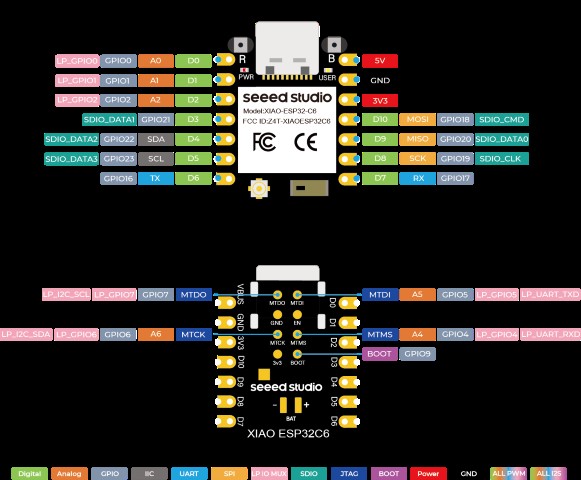
This week, I want to learn about wireless communication, which may be benificial in upgrading my final project. I chose XIAO esp32 c6 microcontroller. Pin out diagram is given below.
 Image
Image
XIAO ESP32C6 is an embedded development board that boasts outstanding RF performance, thanks to its support for both 2.4GHz Wifi - 802.11b/g/n and Bluetooth Low Energy (BLE) 5.0 dual wireless communication. This capability enables the XIAO ESP32C6 to provide reliable and high-speed wireless connectivity for a wide range of Internet of Things (IoT) applications. The board features an onboard ceramic antenna, which eliminates the need for an external antenna and simplifies the design process.
How microcontrollers communicate using WiFi ?
XIAO ESP32-C6 microcontrollers can wirelessly communicate with each other using Wi-Fi by connecting to a shared network or by creating one device as an Access Point (AP). In this setup, the AP microcontroller broadcasts a Wi-Fi network name (SSID) and requires a password for secure access. The other two microcontrollers act as clients (Stations), connecting to this network using the SSID and password. Once all devices are connected, they can communicate using different network protocols. HTTP (Hypertext Transfer Protocol) allows the clients to send requests (like sensor data or commands) to the server, which processes and responds accordingly. UDP (User Datagram Protocol) is faster and more lightweight, ideal for sending small packets directly without establishing a connection, though it doesn’t guarantee delivery. For more flexible multi-device communication, the devices can use MQTT (Message Queuing Telemetry Transport), where one device acts as a broker or connects to an external broker, and each ESP32-C6 can publish or subscribe to specific data topics. Alternatively, the microcontrollers can use ESP-NOW, a fast, connectionless protocol that uses MAC addresses to directly send small messages between devices, without needing an SSID or password at all.
Designing the PCB
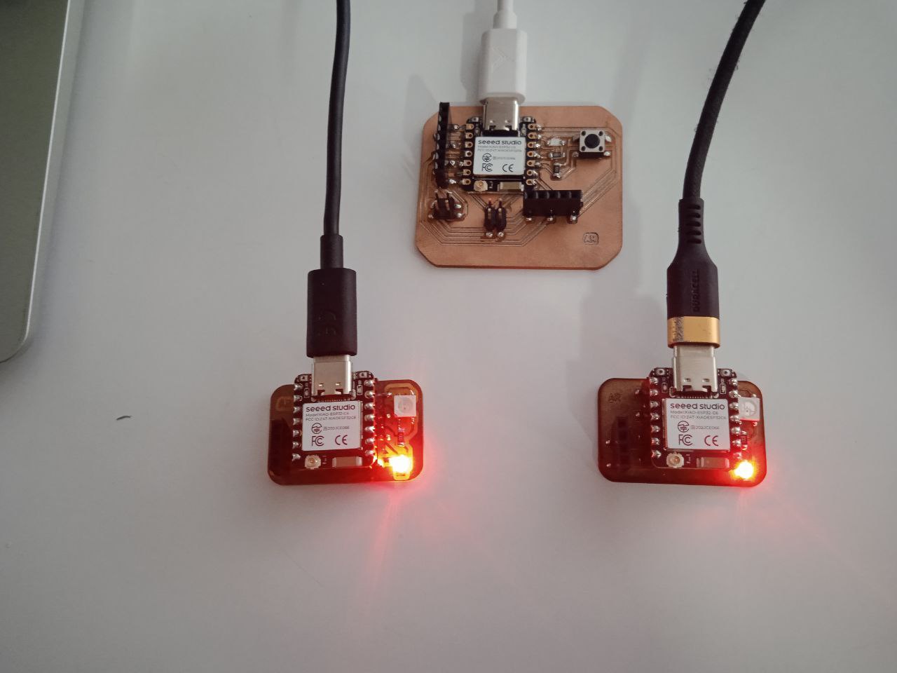
This week, I planned to create two communication nodes. My goal was to use the custom board I designed during Electronics Production week as the main board. The idea was for the NeoPixel LED on each node to light up based on a button press — but only the main board has the button. When the button on the main board is pressed, it should trigger the NeoPixel on the other board to respond accordingly, allowing me to test one-way control through wireless communication. I also wanted to experiment with using a distance sensor and an LED as part of my preparation for the final project. Specifically, I wanted to check if the LED on one board could vary its brightness when the sensor on a different board detects the presence of a person. This would test the feasibility of distributed sensing and responsive lighting across separate nodes — a feature I’m considering integrating into my final project.
To design a PCB in KiCad, we begin by creating a new project, which generates two main files: one for the schematic (.kicad_sch) and another for the PCB layout (.kicad_pcb). In the Schematic Editor, you add components by pressing A, wire them using W, and include power symbols like +5V or GND.Running the Electrical Rules Checker (ERC) helps catch common mistakes.
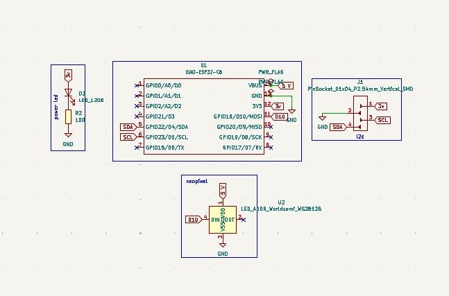
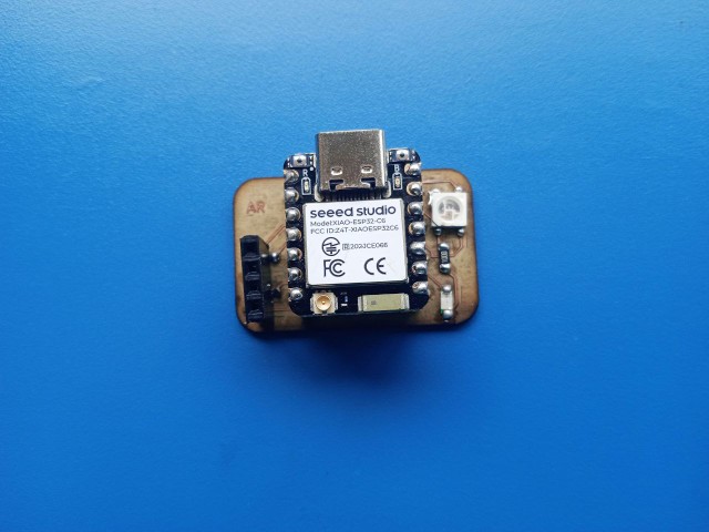
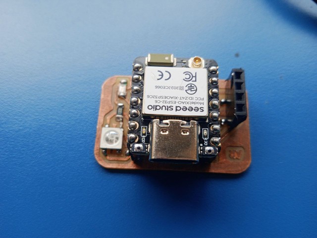
There is a power led, a pin socket to connect sensor module and a neopixel led in the board.
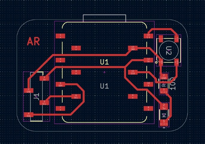
Once complete, we transfer the schematic to the PCB Editor using the "Update PCB from Schematic" tool. In the PCB Editor, drew the board outline on the Edge.Cuts layer. Then route the copper traces using the Route Tracks tool. Finally, a Design Rule Check (DRC) helps ensure there are no layout violations. After verifying the design, we can generate Gerber files for fabrication.
I used Gerber2png software to convert my PCB design's Gerber files into PNG images. After the conversion, I obtained separate images for the trace layer and the outline layer. The trace layer showed the copper connections on the board, illustrating how the components were electrically linked. The outline layer displayed the board’s physical boundary, which I had drawn on the Edge.Cuts layer in KiCad.
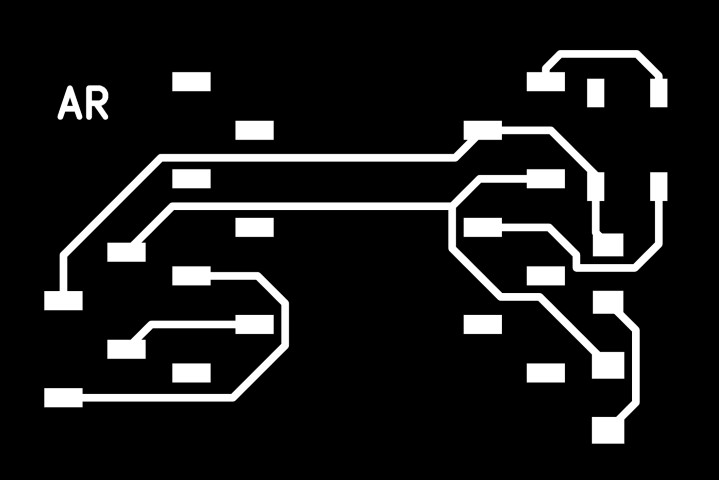

I then uploaded the trace and outline images into mods CE, setting them up for PCB milling.
Milling the PCB
I wanted to make two PCBs. I made one in Modela MDX-20 milling machine and other one in X tool.
Rolland Modela MDX-20 milling machine
I used the FR-1 copper-clad board . I installed a 1/64-inch end mill for milling the traces and carefully set the X, Y, and Z origins, making sure the bit just touched the board’s surface. Using mods CE , I loaded my PNG file, selected the "PCB traces (1/64)" process, and generated the toolpath. I sent the job to the machine and monitored it as it milled the traces. Once done, I changed the bit to a 1/32-inch mill for cutting the board outline, reset the Z-axis, and repeated the process with the appropriate settings. After milling, I removed the board, cleaned it with isopropyl alcohol, and inspected it for any imperfections.
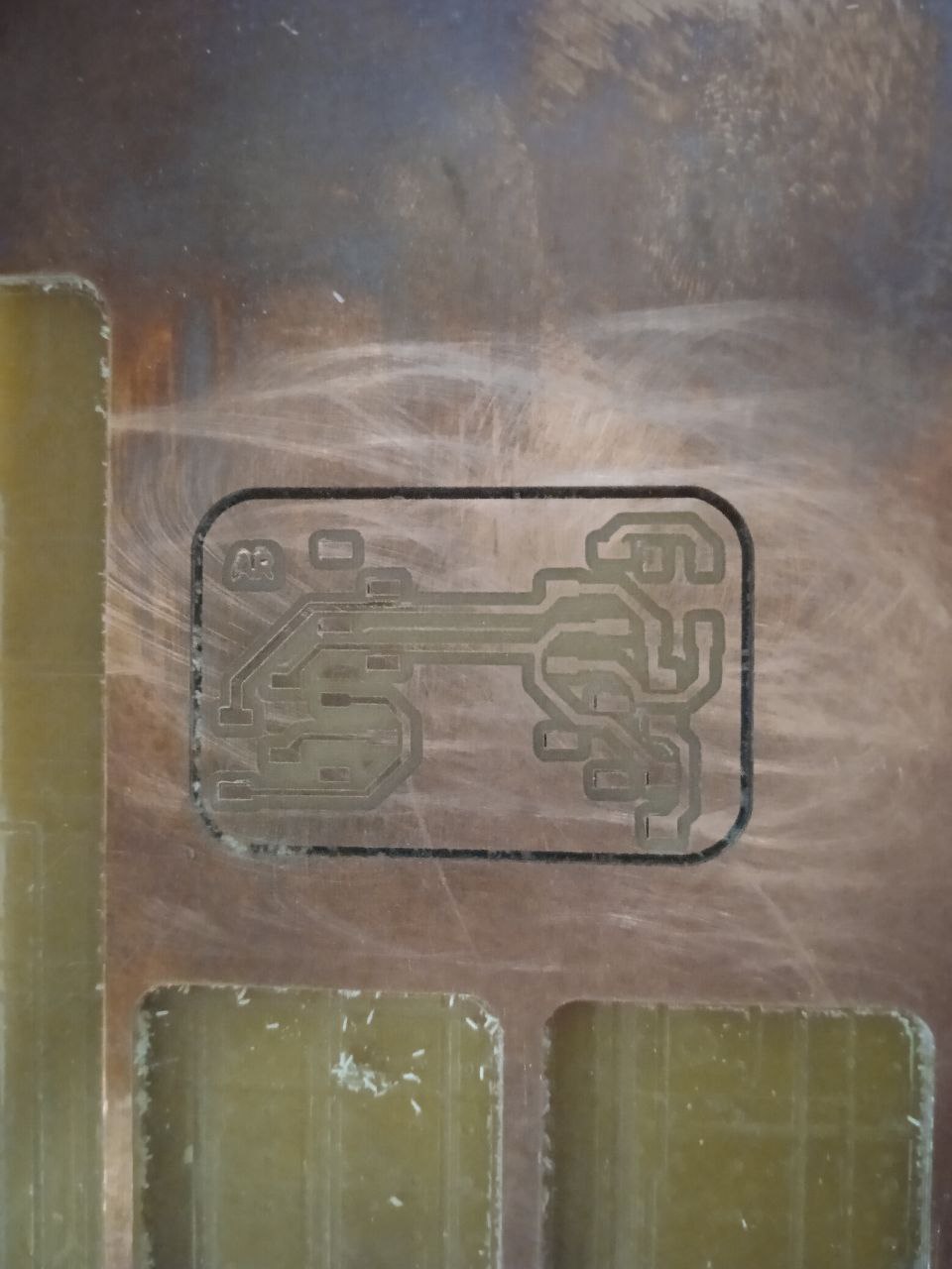
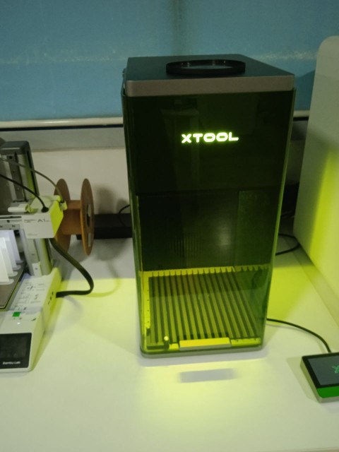
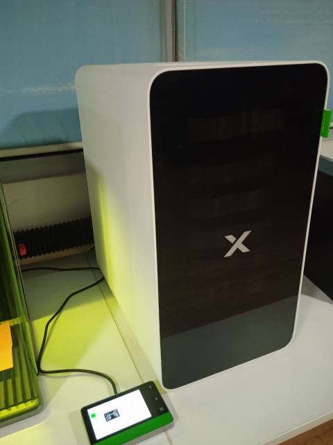
X tool F1 Ultra
 Tutorial
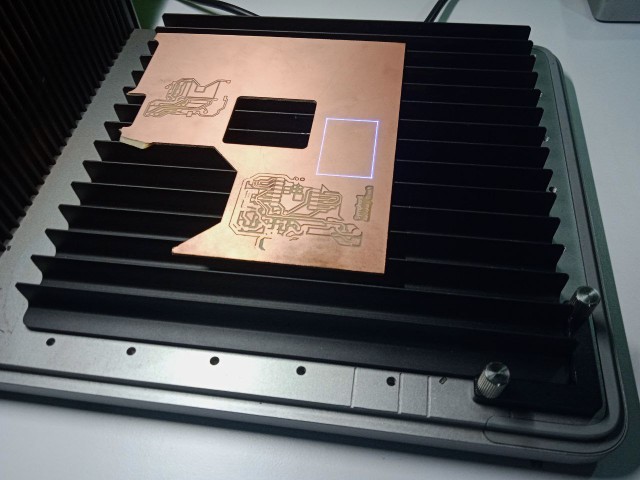
I lifted the protective enclosure of the xTool F1 Ultra and placed my copper-clad board flat on the baseplate, making sure the blue laser spot landed clearly on the surface. To focus the laser, I held down the Up/Down button to adjust the height of the laser module. When the red and blue light spots overlapped perfectly, I knew the focus was set. The F1 Ultra is equipped with two types of lasers: a blue diode laser for cutting and engraving wood, acrylic, and plastics, and a infrared fiber laser for engraving metals and marking PCBs. For my PCB work, I used the infrared fiber laser, which is ideal for ablating thin copper layers and blue laser for outline cut. In xTool Creative Space (XCS), I used the left-side tools to create or import my PCB design onto the canvas. I selected the design object, used the top toolbar for edits, and set the engraving and cutting parameters on the right—adjusting power, speed, and number of passes. Before starting, I used the Framing function to preview the engraving area—the laser dot traced the border of the design directly on the board, helping me confirm its position.
 I also made sure the xTool Smoke Purifier was connected to the exhaust port at the back of the F1 Ultra.
 Once everything was set, I clicked Process in XCS, closed the protective enclosure, and hit Start in the software. When the display showed “Ready,” I pressed the Start/Stop button on the machine’s touchscreen controller to begin engraving. Once finished, the cutting process is loaded the same way.
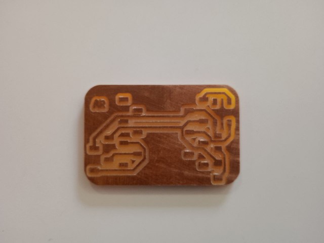
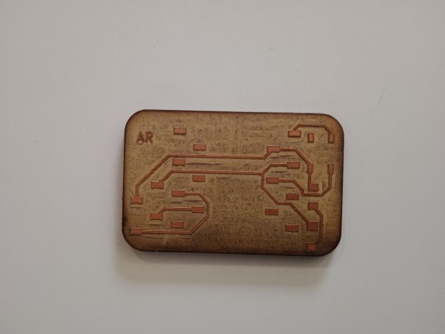
The final board
Assembling the components
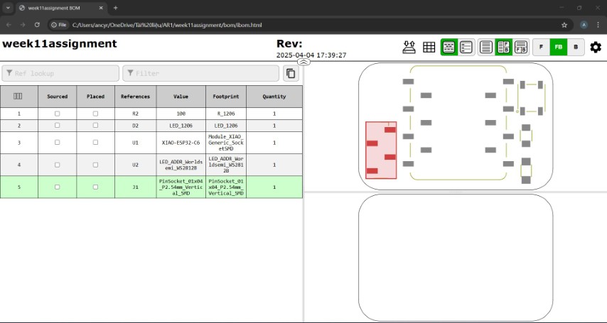
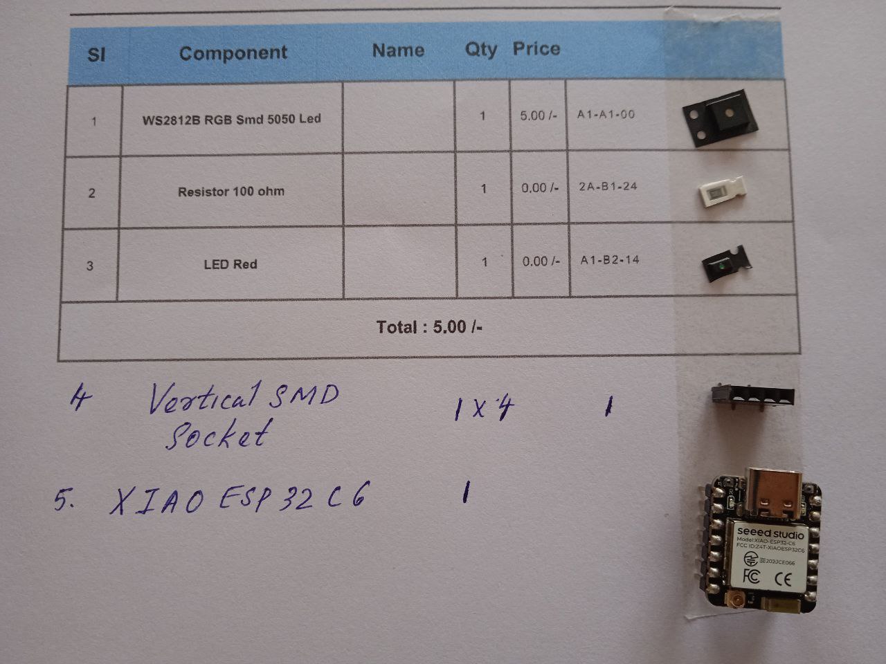
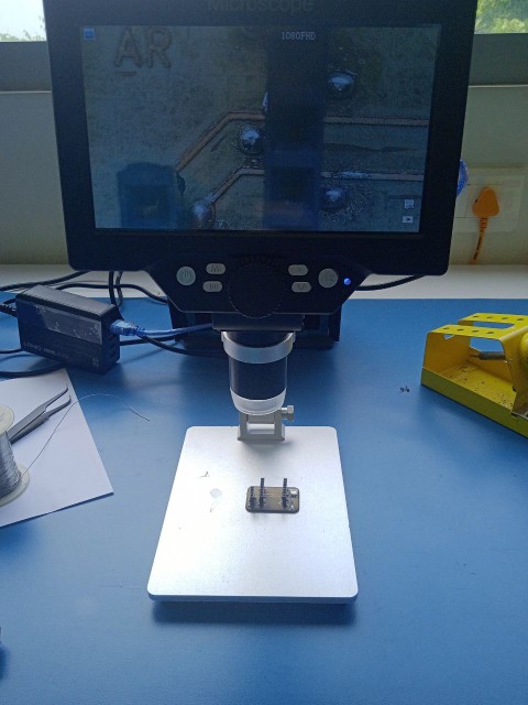
I had two PCBs to assemble as I was planning to add two nodes. A board was already built in electronics design week.I used the Interactive HTML BOM to identify and source the required components from FabStash. After receiving the parts, I soldered them onto the PCB. Post-soldering, I inspected the board both visually under a microscope to check for solder bridges, alignment, and cold joints, and electrically using a multimeter to verify continuity and proper connections.
Final PCB
Inspecting the PCBs
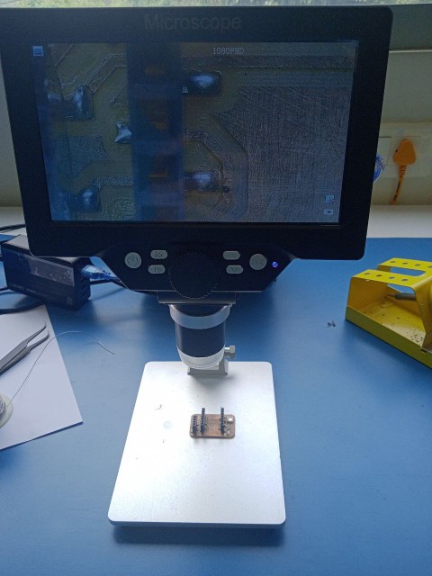
mistakes : I tried to connect VL53L0X sensor. But microcontroller didn't detect the device. With the help of Instructor, it was later found that the I2C connection were not proper.After I resoldered the connector, the sensor was detected by the board
Communication between the PCBs
esp-now
ESP-NOW is a wireless communication protocol developed by Espressif that allows ESP32 and other compatible devices to exchange data directly without relying on Wi-Fi or an internet connection. It operates over the 2.4 GHz frequency band and supports fast, low-power, and efficient peer-to-peer communication. Devices must be paired beforehand, but once paired, they can reconnect automatically even after a reset or power loss—no additional handshake is required. ESP-NOW supports both encrypted and unencrypted communication, allows a mix of secure and open peers, and can transmit payloads up to 250 bytes. It also includes a callback feature to notify whether a message was successfully delivered, making it well-suited for applications like sensor networks, remote monitoring, and other IoT systems that require quick, lightweight data exchange.
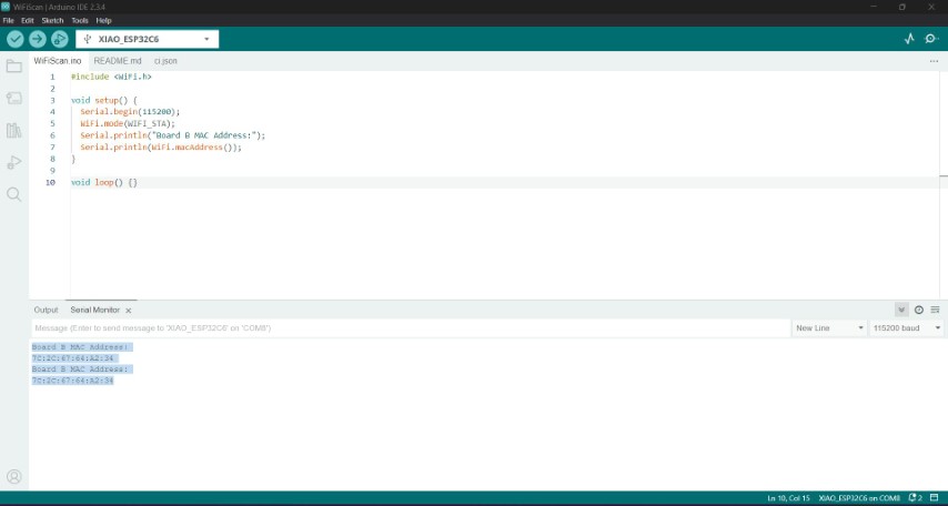
To connect xiao esp32 c6 boards we need mac address of the reciever. To find the mac address, I used the following code.Make sure to set the corret baud rate in serial monitor. I got the code from AI overview in chrome.
#include <WiFi.h>                   // Include the WiFi library for accessing WiFi functions like getting MAC address
  void setup() {
    Serial.begin(115200);            // Start the serial communication at 115200 baud rate for debugging and output
    WiFi.mode(WIFI_STA);             // Set the WiFi mode to Station (client) mode; needed to get MAC address properly
    Serial.println("Board B MAC Address:");  // Print a label to indicate the following value is the MAC address
    Serial.println(WiFi.macAddress());       // Retrieve and print the MAC address of the board
}

  void loop() {
  // Empty loop since we only need to print the MAC address once in setup()
}
Changing intesity of led in node using data from distance sensor in main board
I browsed to get code to connect the MCUs.I got some codes from AI overview in chrome. There were mistakes. I copied the error messages and uploaded in chatgpt to correct the code. Then I used chatgpt to refer the code.
- Prompt 1: I want ESP32-C6 code to communicate using ESP-NOW.
- Prompt 2:I have a VL53L0X sensor and a red LED. I want to change the intensity of the LED with respect to the sensor.
- Prompt 3:The sensor is in one ESP32-C6 and the LED is in another ESP32-C6.
I wanted one MCU to send the data from VL53L0X time of flight sensor. Program of the sender is given below
#include <WiFi.h>                  // Include WiFi library for ESP32 (needed for ESP-NOW)
#include <esp_now.h>               // Include ESP-NOW library for peer-to-peer communication
#include <Wire.h>                  // Include I2C communication library
#include <VL53L0X.h>               // Include library for the VL53L0X distance sensor

// Create sensor object
VL53L0X sensor;

// Define the MAC address of the receiving ESP32 board (replace with actual receiver MAC)
uint8_t peerAddress[] = { 0x7C, 0x2C, 0x67, 0x64, 0xA2, 0x34 };

// Define the structure of the message to be sent
typedef struct struct_message {
  int distance_cm;                 // Distance in centimeters
} struct_message;

struct_message msg;                // Create a message instance

void setup() {
  Serial.begin(115200);            // Initialize serial communication for debugging

  // Initialize I2C communication
  Wire.begin();

  // Initialize VL53L0X distance sensor
  sensor.setTimeout(500);          // Set timeout in milliseconds
  if (!sensor.init()) {            // Check if sensor initialization failed
    Serial.println("VL53L0X Init Failed");
    while (1);                     // Halt execution
  }
  Serial.println("VL53L0X Ready");

  // Set WiFi mode to Station (client) to enable ESP-NOW
  WiFi.mode(WIFI_STA);

  // Initialize ESP-NOW
  if (esp_now_init() != ESP_OK) {
    Serial.println("ESP-NOW init failed");
    return;
  }

  // Setup peer info struct for the receiver
  esp_now_peer_info_t peerInfo = {};
  memcpy(peerInfo.peer_addr, peerAddress, 6);  // Copy receiver's MAC to peer info
  peerInfo.channel = 0;                        // Use default channel
  peerInfo.encrypt = false;                    // Disable encryption

  // Add the peer
  if (esp_now_add_peer(&peerInfo) != ESP_OK) {
    Serial.println("Failed to add peer");
    return;
  }
}

void loop() {
  int distance = sensor.readRangeSingleMillimeters();  // Read distance in mm
  if (sensor.timeoutOccurred()) {
    Serial.println("Timeout");                         // Print timeout message
    return;                                            // Skip sending if timeout occurred
  }

  int distance_cm = distance / 10;                     // Convert mm to cm
  msg.distance_cm = distance_cm;                       // Store in message struct

  Serial.print("Sending distance (cm): ");
  Serial.println(distance_cm);                         // Print distance to serial monitor

  // Send the message to the receiver via ESP-NOW
  esp_now_send(peerAddress, (uint8_t *)&msg, sizeof(msg));

  delay(500);                                           // Wait before next reading and send
}
The receiver MCU needs to change the intensity of led according to the data from sender. Program code of receiver is given below.
#include <WiFi.h>                  // Include WiFi library
#include <esp_now.h>               // Include ESP-NOW library

#define LED_PIN 18                    // Define the pin connected to the LED

// Define the structure for incoming messages
typedef struct struct_message {
  int distance_cm;                   // Distance value in centimeters
} struct_message;

struct_message msg;                  // Create a message struct to hold incoming data

// Callback function triggered when ESP-NOW data is received
void OnDataRecv(const esp_now_recv_info_t *recv_info, const uint8_t *incomingData, int len) {
  memcpy(&msg, incomingData, sizeof(msg));   // Copy the received data into msg
  Serial.print("Received distance: ");
  Serial.print(msg.distance_cm);
  Serial.println(" cm");

  // Map distance (0–20 cm) to brightness (255–0)
  int brightness = map(msg.distance_cm, 0, 20, 255, 0);
  brightness = constrain(brightness, 0, 255);  // Ensure brightness stays within 0–255

  // Set the LED brightness
  analogWrite(LED_PIN, brightness);           // PWM control of LED brightness
}

void setup() {
  Serial.begin(115200);                       // Start serial monitor

  pinMode(LED_PIN, OUTPUT);                   // Set LED pin as output

  WiFi.mode(WIFI_STA);                        // Set WiFi mode to station
  WiFi.disconnect();                          // Ensure it doesn't try to connect to a WiFi network

  if (esp_now_init() != ESP_OK) {
    Serial.println("Error initializing ESP-NOW"); // Error check
    return;
  }

  // Register the receive callback function
  esp_now_register_recv_cb(OnDataRecv);

  Serial.println("ESP-NOW Receiver Ready");   // Confirmation message
}

void loop() {
  // No code needed here; everything handled in the receive callback
}
The result is given below
Turning on neo pixel in nodes using push button in main board
I used chatgpt to get the code. The prompt is given below.
- I want to use ESP-NOW to communicate between three ESP32-C6 microcontrollers. The sender has a switch. When it's pressed the first time, the NeoPixel on Board 2 should light up. On the second press, the NeoPixel on Board 3 should light up. On the third press, both should turn off."
- The NeoPixel is connected to GPIO 18 on both receiver boards
- Here's the code I’m using to detect button presses and blink an LED based on how many times the button is pressed. Please adapt it for the ESP32-C6 and ESP-NOW
- I don't need an internal pull-up resistor for the button
- I want the NeoPixels to change colors when turned on. They should cycle through different colors one after another
- add the color cycling functionality into the code and give me final, working sender and receiver code for the ESP32-C6 boards using ESP-NOW
- On the third button press, both NeoPixels should turn off
- Why is my ESP32-C6 BOOT button acting like a regular switch instead of functioning like a BOOT button
- Here's my full ESP32-C6 receiver code using ESP-NOW and NeoPixel. It's giving an error about the callback function signature — how can I fix it
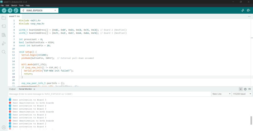
Sender
#include <WiFi.h>              // Include WiFi library (required for ESP-NOW)
#include <esp_now.h>           // Include ESP-NOW library for communication

// Define MAC addresses of the two receiver boards
uint8_t board2Address[] = {0x8C, 0xBF, 0xEA, 0xCB, 0x7E, 0xC8}; // Board 2 (NeoPixel)
uint8_t board3Address[] = {0x7C, 0x2C, 0x67, 0x64, 0xBA, 0xF8}; // Board 3 (NeoPixel)

int pressCount = 0;             // Tracks number of button presses
bool lastButtonState = HIGH;    // Stores the last state of the button
const int buttonPin = 9;        // Pin where the button is connected

void setup() {
  Serial.begin(115200);         // Start serial communication for debugging
  pinMode(buttonPin, INPUT);    // Set button pin as input (external pull-down resistor assumed)

  WiFi.mode(WIFI_STA);          // Set ESP32 to station mode (required for ESP-NOW)

  if (esp_now_init() != ESP_OK) {
    Serial.println("ESP-NOW init failed!");
    return;
  }

  // Add first peer (Board 2)
  esp_now_peer_info_t peerInfo = {};
  memcpy(peerInfo.peer_addr, board2Address, 6); // Copy MAC address
  peerInfo.channel = 0;
  peerInfo.encrypt = false;
  esp_now_add_peer(&peerInfo);

  // Add second peer (Board 3)
  memcpy(peerInfo.peer_addr, board3Address, 6);
  esp_now_add_peer(&peerInfo);
}

void loop() {
  bool currentButtonState = digitalRead(buttonPin); // Read current state of the button

  // Detect falling edge (HIGH to LOW) = button press
  if (lastButtonState == HIGH && currentButtonState == LOW) {
    pressCount++; // Increment button press count

    uint8_t msgToBoard2 = 0;
    uint8_t msgToBoard3 = 0;

    if (pressCount % 3 == 1) {
      msgToBoard2 = 1; // Activate Board 2 only
      msgToBoard3 = 0;
      esp_now_send(board2Address, &msgToBoard2, sizeof(msgToBoard2));
      esp_now_send(board3Address, &msgToBoard3, sizeof(msgToBoard3));
      Serial.println("➡️ Sent activation to Board 2");
    }
    else if (pressCount % 3 == 2) {
      msgToBoard2 = 0;
      msgToBoard3 = 1; // Activate Board 3 only
      esp_now_send(board2Address, &msgToBoard2, sizeof(msgToBoard2));
      esp_now_send(board3Address, &msgToBoard3, sizeof(msgToBoard3));
      Serial.println("➡️ Sent activation to Board 3");
    }
    else {
      // Every third press: deactivate both
      msgToBoard2 = 0;
      msgToBoard3 = 0;
      esp_now_send(board2Address, &msgToBoard2, sizeof(msgToBoard2));
      esp_now_send(board3Address, &msgToBoard3, sizeof(msgToBoard3));
      Serial.println("⛔ Sent deactivation to both boards");
    }

    delay(200); // Simple debounce
  }

  lastButtonState = currentButtonState; // Update button state
}
Receiver
#define NEO_RMT  // Use RMT peripheral for NeoPixel on ESP32-C6
#include <WiFi.h>               // WiFi library for ESP-NOW
#include <esp_now.h>            // ESP-NOW communication library
#include <Adafruit_NeoPixel.h>  // NeoPixel control library
#include "esp_sleep.h"             // To disable unwanted deep sleep wakeups

#define LED_PIN 18                  // GPIO pin connected to NeoPixel
#define NUM_PIXELS 1                // Only one NeoPixel used

Adafruit_NeoPixel pixels(NUM_PIXELS, LED_PIN, NEO_GRB + NEO_KHZ800);  // Initialize NeoPixel

bool active = false;               // Whether the board is active (receiving 1 from master)
int colorIndex = 0;                // Current color index for cycling

void setup() {
  Serial.begin(115200);            // Start serial for debugging

  // Prevent the ESP32-C6 from going into light/deep sleep that breaks NeoPixel
  esp_sleep_disable_wakeup_source(ESP_SLEEP_WAKEUP_ALL);

  pixels.begin();                  // Initialize NeoPixel
  pixels.clear();                  // Turn off all pixels
  pixels.show();                   // Push state to pixel

  WiFi.mode(WIFI_STA);            // Set WiFi mode to station
  WiFi.disconnect();              // Disable connection to AP (r
And the result
How ESP-NOW Communication Works
ESP-NOW is a peer-to-peer wireless protocol that allows ESP32 devices to send small data packets to specific devices using their MAC addresses (Media Access Control – unique identifiers per device).
How Boards Are Addressed
In your controller (sender) code, you define two ESP32 boards using their MAC addresses:
 uint8_t board2Address[] = {0x8C, 0xBF, 0xEA, 0xCB, 0x7E, 0xC8}; // Board 2 (NeoPixel)
uint8_t board3Address[] = {0x7C, 0x2C, 0x67, 0x64, 0xBA, 0xF8}; // Board 3 (NeoPixel)
Each MAC address is a 6-byte identifier unique to the hardware. These addresses tell the ESP-NOW protocol exactly which device to send messages to.
You add each board as a peer to the ESP-NOW network:
  esp_now_peer_info_t peerInfo = {};
memcpy(peerInfo.peer_addr, board2Address, 6);
esp_now_add_peer(&peerInfo);  // Adds Board 2

memcpy(peerInfo.peer_addr, board3Address, 6);
esp_now_add_peer(&peerInfo);  // Adds Board 3
This means your controller can now send messages to either board individually using esp_now_send().
How You Send Messages to Only One Board
In the loop() function of your controller, you check for button presses and use a counter pressCount to determine which board to activate:
 if (pressCount % 3 == 1) {
  msgToBoard2 = 1; // Activate Board 2
  msgToBoard3 = 0;
} else if (pressCount % 3 == 2) {
  msgToBoard2 = 0;
  msgToBoard3 = 1; // Activate Board 3
} else {
  msgToBoard2 = 0;
  msgToBoard3 = 0; // Deactivate both
}
You then send each message to its respective board:
  esp_now_send(board2Address, &msgToBoard2, sizeof(msgToBoard2));
esp_now_send(board3Address, &msgToBoard3, sizeof(msgToBoard3));
So, even if both messages are sent every time, each board only reacts to its own message. The receiver only listens for 0 or 1 and acts accordingly.
Hero shot
Files
DesignfilesGroup assignment
In the group assignment, two separate projects were successfully connected using ESP-NOW communication. Ashish’s board was equipped with an RFID reader and programmed to detect two different RFID tags. When the first tag was scanned, the board sent a message via ESP-NOW to Ancy’s first board, which responded by lighting up a NeoPixel LED in red. When the second tag was scanned, a different message was sent to Ancy’s second board, triggering its NeoPixel to light up in green. This communication was made possible by using the unique MAC addresses of the receiver boards, allowing Ashish’s board to send specific messages to each target.
Group assignment pageConclusion
This week, I explored wireless communication using ESP-NOW with the XIAO ESP32-C6 microcontrollers, and it was a valuable learning experience that I believe can benefit my final project. I designed and fabricated two custom PCBs using both the Roland MDX-20 milling machine and the xTool F1 Ultra. I successfully established ESP-NOW communication between the boards by using their MAC addresses to send data directly without relying on a Wi-Fi network. I also implemented a system where pressing a button on one board sends a signal to two receivers, each with a NeoPixel that changes color when selected—demonstrating how nodes can wirelessly communicate and respond to specific commands. In another test, I transmitted distance data from a VL53L0X sensor to a receiver that adjusted LED brightness in real time.