Objectives
Group assignment:
- characterize the design rules for your in-house PCB production process
- submit a PCB design to a board house
- make and test a microcontroller development board that you designed ,extra credit: make it with another process
Group Assignment
PCB fabrication involves design validation, layer etching, drilling, plating, solder masking, and final profiling. Using the Roland MDX-20 milling machine, PCB traces are precisely cut, with minimum trace spacing of ≥17 mils and widths of ≥10 mils for reliability. Alternatively, the XTool F1 Ultra laser engraver offers a faster, non-contact approach by vaporizing copper to form traces, but challenges like overburning and limited depth control affect precision. Testing with a Trotec laser cutter showed poor results due to inconsistent engraving. While milling remains reliable, laser engraving shows potential with further optimization for fine detail and consistency.
Result
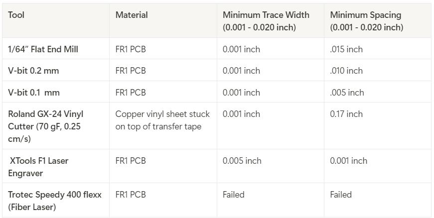 group assignment page
8. ELECTRONICS PRODUCTION
Modela MDX-20 3D Milling Machine
.jpeg)
The Roland Modela MDX-20 is a compact and highly versatile desktop milling machine developed by Roland DG Corporation. Designed for precision milling, carving, and engraving, it is capable of working with a range of materials, including plastic, wood, resin, and non-ferrous metals. With its ability to produce fine details, the MDX-20 is widely used in prototyping, model making, jewelry design, and small-scale manufacturing.
Gerber files
Gerber files are the standard file format used in the PCB industry to communicate design data from designers to manufacturers. They contain precise instructions for fabricating a PCB, specifying the layout of copper traces, pads, vias, solder masks, silkscreen markings, and drill holes. Each PCB layer is represented by a separate Gerber file, and the format uses ASCII-based vector commands to define shapes and positions. Generated by PCB design software such as KiCad, Altium, or Eagle, these files guide manufacturing processes like CNC milling, photoplotting, and etching.
The design was made in KiCad and changed to gerbers in electronics design week.To change it gerber format file -> fabrication outputs -> gerbers
.jpg)
The file is then extracted and uploaded to Gerber2PNG. The file is coverted to PNG file
.jpeg) Gerber2PNG
Gerber2PNG
The file is then fed to Mods master.
Milling the PCB
Secure the copper-clad board onto the machine’s bed using double-sided tape to prevent movement.
.jpg)
.jpg)
Insert the appropriate engraving or milling bit. I used V Bit 0.2 mm 60 deg for engraving the circuit traces and flat endmill 1/32" for cutting.
.jpg)
Mods CE : Mods is a modular, cross-platform software environment originally developed by MIT’s Center for Bits and Atoms (CBA) for digital fabrication workflows. It consists of independent but interconnected modules that can be used to create custom toolchains for CAD, CAM, machine control, automation, and sensor input processing. Running in a browser, Mods allows users to design flexible workflows for specific machines and processes, making it a powerful tool for fabrication labs. Mods CE (Community Edition) is an open-source fork that enhances usability and expands features with community support.
We need to set the origin. I chose x:7 and y:4.7 mm "move to origin" button sets the machine to origin. "position to change bit" button is used to change the bit.
.jpeg)
Trace of PCB
To upload the trace layer, upload the png file. We use 0.2mm 60 deg V bit. We need to specify the parameters. Offset number: 4, Offset stepover is selected as 0.2 and feed speed as 4 mm/s. Then click on send calculated settings, click calculate and click on send file.
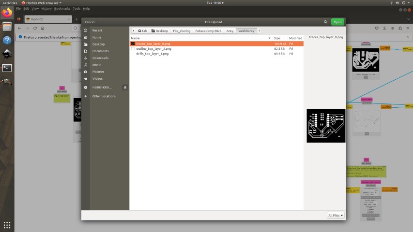
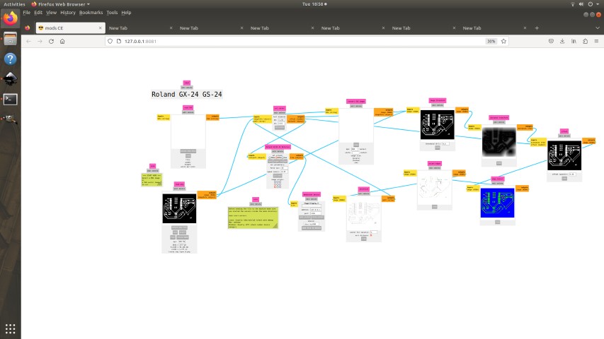
We can click on view to see the toolpath
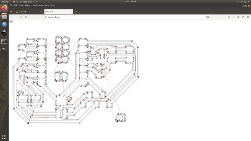
Set the zero position (X, Y, and Z-axis) manually. Adjust milling parameters like spindle speed, feed rate, and depth of cut based on the material and tool specifications. Start the first engraving pass to remove the copper layer and create the circuit traces according to the design. If required, perform multiple passes to ensure clean and accurate cuts, especially for fine or narrow traces.
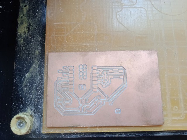
Outline of PCB
We can upload the outline the same way we send the trace layer. One thing to remember is to change the bit. We use 1/32" bit.Offset number:1 and speed:4 mm/s
.jpeg)
From view option we can see the toolpath
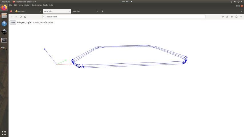
Change to a drill bit (e.g., 0.8mm or 1mm) for component holes. Load the Drill file and perform drilling.In my file there wasn't drilling.So the next step was to cut cut out the final PCB board shape.I switched the V Bit to end mill 1/32". Ensure the cut depth is enough to fully separate the PCB from the copper-clad sheet.
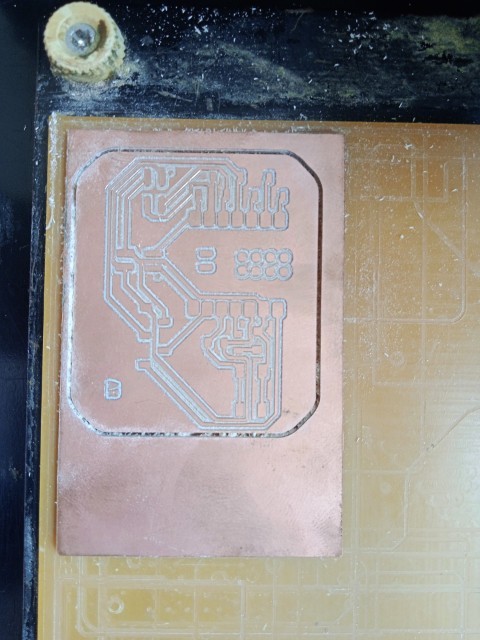
Use a vaccum cleaner to remove the dust and debris.carefully insert a scraper under one edge of the PCB. Slowly lift the board while applying even pressure to avoid bending or damaging it.
.jpg)
If tape residue remains on the PCB, clean it with isopropyl alcohol (IPA) and a cloth.
.jpg)
In KiCad, you can generate an Interactive HTML Bill of Materials (BOM) using theInteractive HTML BOM (iBOM) plugin. This plugin creates a web-based BOM that allows easy visualization and selection of components on the PCB. Plug-in and content manager -> Interactive HTML BOM
.jpeg)
The plugin will launch and generate an interactive BOM.
.jpeg)
The print of the BOM is taken. The next step was to login in fabstash and request components. Fab stash is a library of all available components in the inventory of superfab lab kochi.
.jpg)
FabStash
Soldering
Work bench
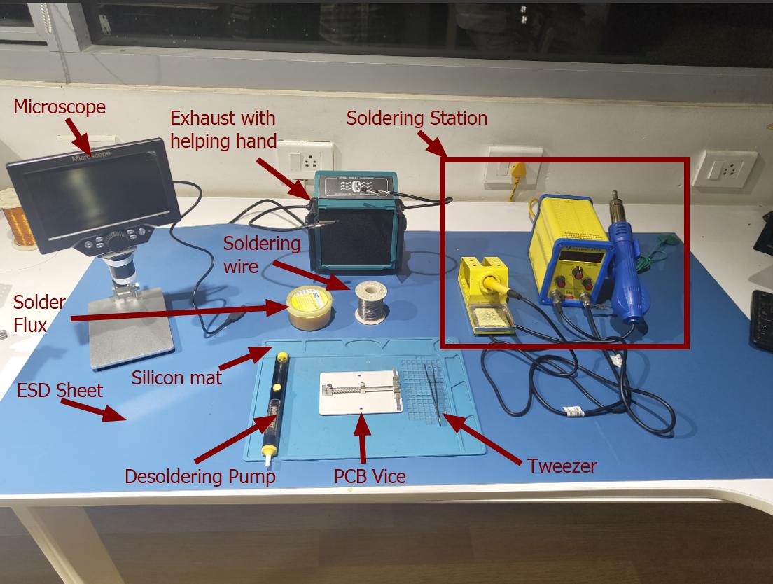
- Microscope: Assists with inspecting small components and fine solder joints.
- Exhaust with helping hand: Removes solder fumes and holds PCBs or wires in place.
- Soldering Station: Includes a temperature-controlled soldering iron and hot air gun for precise soldering and desoldering.
- Solder Wire: Melted to form joints between components and pads.
- Solder Flux: Improves solder flow and prevents oxidation.
- ESD Sheet: Protects sensitive components from electrostatic discharge.
- Silicon Mat: Heat-resistant surface for safe soldering.
- Desoldering Pump: Removes solder from joints during rework.
- PCB Vice: Holds the PCB securely while soldering.
- Tweezer: Handles small components precisely.
Turn on the soldering iron and let it reach the proper temperature. While the joint is hot, feed the solder wire to the junction.Allow the solder to flow around the joint, creating a small, shiny, and conical shape. Remove the solder first, then the iron. Let the joint cool naturally without movement. I began the soldering process by working on the small components first. To secure each component, I applied solder (lead) to one pad, positioned the component, and fixed one side. Once it was stable, I continued soldering the remaining pins to their respective pads.
.jpg)
Challenges :While soldering, I accidentally lost an SMD LED—it slipped and jumped out of my hand. Due to its small size, I couldn't locate it despite searching the workspace. As a result, I had to request a replacement through FabStash.
.jpg)
The pinout of the board is shown below
.jpg)
Inspection
Use magnification (a magnifying glass or microscope) for detailed inspection. Set the multimeter to continuity mode (beeps when a circuit is closed). Probe between adjacent pads and traces to check for unwanted connections.
Mistake :-During inspection under the microscope, I noticed that some solder joints were not neat and required rework. I carefully re-soldered them to ensure proper connections and a cleaner finish.
.jpg)
Programming the board
I used the example program in arduino to program my pcb and changed the pin numbers.
Blink the led
Files-> examples-> Basics-> Blink
// the setup function runs once when you press reset or power the board
                void setup() {
                  // initialize digital pin LED_BUILTIN as an output.
                  pinMode(D10, OUTPUT);
                }

                // the loop function runs over and over again forever
                void loop() {
                  digitalWrite(D10, HIGH);  // turn the LED on (HIGH is the voltage level)
                  delay(1000);                      // wait for a second
                  digitalWrite(D10, LOW);   // turn the LED off by making the voltage LOW
                  delay(1000);                      // wait for a second
                }
Turn ON/OFF led using switch
const int buttonPin = D9;  // the number of the pushbutton pin
                  const int ledPin = D10;    // the number of the LED pin

                  // variables will change:
                  int buttonState = 0;  // variable for reading the pushbutton status

                  void setup() {
                    // initialize the LED pin as an output:
                    pinMode(ledPin, OUTPUT);
                    // initialize the pushbutton pin as an input:
                    pinMode(buttonPin, INPUT);
                  }

                  void loop() {
                    // read the state of the pushbutton value:
                    buttonState = digitalRead(buttonPin);

                    // check if the pushbutton is pressed. If it is, the buttonState is LOW:
                    if (buttonState == LOW) {
                      // turn LED on:
                      digitalWrite(ledPin, HIGH);
                    } else {
                      // turn LED off:
                      digitalWrite(ledPin, LOW);
                    }
                  }
Switch controlled blinking sequence.
I used chatgpt for code reference. Prompt used :write a program to blink an led with switch it has to blink one time when pressed first two times in second press 3 times in third press then turn off at the fourth press.
int pressCount = 0;     // Track button presses
                    bool buttonState = HIGH;
                    bool lastButtonState = HIGH;

                    void setup() {
                        pinMode(D10, OUTPUT);
                        pinMode(D9, INPUT);  // Internal pull-up for button
                        Serial.begin(115200);
                        Serial.println("Press the button to control LED blinking.");
                    }

                    void loop() {
                        buttonState = digitalRead(D9);

                        // Detect button press (falling edge detection)
                        if (lastButtonState == HIGH && buttonState == LOW) {
                            pressCount++;   // Increment press count
                            Serial.print("Button pressed! Count: ");
                            Serial.println(pressCount);

                            // Blink LED based on press count
                            if (pressCount == 1) {
                                blinkLED(1);
                            } else if (pressCount == 2) {
                                blinkLED(2);
                            } else if (pressCount == 3) {
                                blinkLED(3);
                            } else {
                                Serial.println("Turning off LED.");
                                digitalWrite(D10, LOW); // Ensure LED is OFF
                                pressCount = 0;  // Reset count after 4th press
                            }
                        }

                        lastButtonState = buttonState;  // Store last button state
                        delay(50);  // Debounce delay
                    }

                    // Function to blink LED a given number of times
                    void blinkLED(int times) {
                        for (int i = 0; i < times; i++) {
                            digitalWrite(D10, HIGH);
                            delay(300);
                            digitalWrite(D10, LOW);
                            delay(300);
                        }
                    }
Conclusion
The process of electronics production using the Roland Modela MDX-20 involved multiple stages, including PCB design, milling, soldering, inspection, and programming. By designing the circuit in KiCad, generating Gerber files, and converting them into PNG format using Gerber2PNG, I successfully prepared the board for fabrication. Using Mods CE, I set the milling parameters, positioned the machine, and carefully milled both the trace and outline of the PCB using appropriate bits. After cutting out the board and cleaning it, I proceeded with soldering the components, ensuring proper connections. A continuity test using a multimeter confirmed the integrity of the circuit. Finally, I programmed the board using Arduino IDE, testing different functionalities like blinking an LED, controlling it with a switch, and implementing a switch-controlled blinking sequence.
Files
DesignfilesHeroshot
.jpg)