Objectives
Group assignment:-do your lab's safety training test runout, alignment, fixturing, speeds, feeds, materials, and toolpaths for your machine.
Individual assignment make (design+mill+assemble) somethingbig (~meter-scale) extra credit: don't use fasteners or glue extra credit: include curved surfaces.
Group assignment
In group assignment we learned about safety measures. We made a jig to test fit. We learned to operate shopbot cnc machine, its speeds, feeds, material and toolpaths.Key aspects of safety training include using Personal Protective Equipment (PPE), following safe behavior practices, conducting pre-operation checks, and adhering to machine operation guidelines. Maintaining a clean workspace, preparing for emergencies, and continuously improving safety procedures further contribute to a secure and efficient working environment.
group assignment page7.COMPUTER CONTROLLED MACHINING
CNC (Computer Numerical Control) machining is a precise and automated manufacturing process where pre-programmed software controls the movement of machines and tools. It uses a specialized language called G-code to dictate cutting speed, feed rate, and tool paths, enabling machines to cut, drill, grind, and shape materials with high accuracy. CNC machining relies on CAD (Computer-Aided Design) and CAM (Computer-Aided Manufacturing) software to generate instructions, allowing for the efficient production of complex parts from materials like metal, plastic, and wood. This process enhances precision, reduces manual labor, increases efficiency, and lowers production costs, making it essential in industries such as aerospace, automotive, and manufacturing.
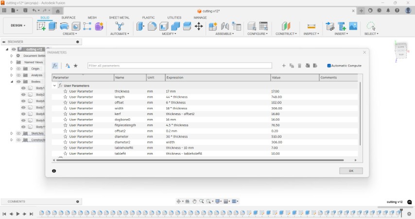
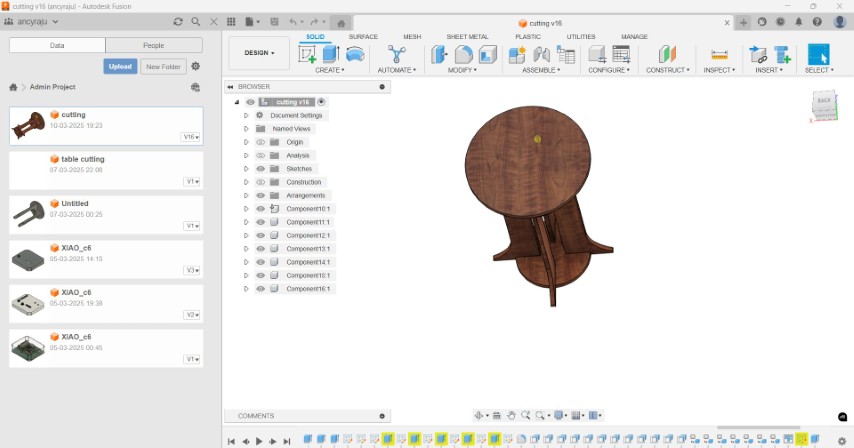
Designing a coffee table
This week, I wanted to try to make a coffee table. I drew an intial skecth and designed a 3D model in fusion.I made a parametric design.
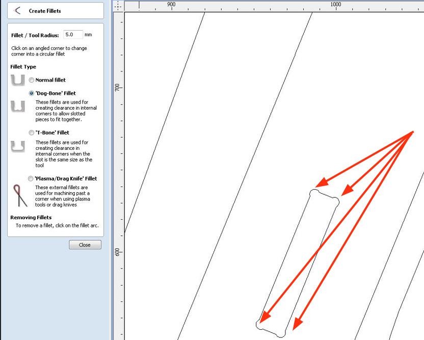
Dogbones
Dogbones are important because a round CNC tool cannot make perfectly sharp internal corners it always leaves a rounded edge. Without dogbones, the mating piece wouldn’t fit properly unless manually filed. I added dogbone fillets in VCarve as part of the CAM processing. We can also add dogbone plug-in to create dogbones in fusion. To add the dogbone plugin in Fusion 360, start by downloading the dogbone add-in file (usually a .py script or folder). Open Fusion 360 and go to the Utilities tab, then click on Add-Ins. In the Scripts and Add-Ins window, click on the Add-Ins tab and choose Open Add-Ins Folder. Paste the downloaded dogbone folder into this directory. After restarting Fusion or refreshing the Add-Ins window, you will see the dogbone icon appear in the design workspace. You can now use this tool to automatically add dogbone fillets to internal corners for CNC-ready designs. From the link below you can download the dogbone file.
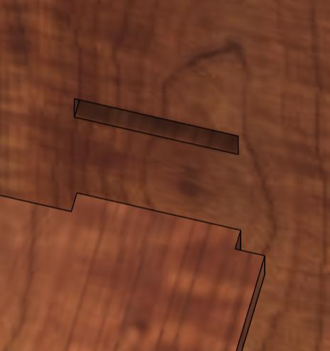
dogboneTab and slot joint
A tab and slot joint works by inserting a protruding piece (the tab) on one part into a matching hole (the slot) on another part. When the two parts are pushed together, the tabs fit snugly into the slots, locking the pieces in place—like puzzle pieces.
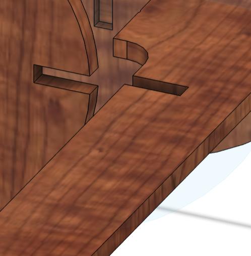
Cross halved joint
Two parts cross each other at 90° (like a “+”). Each has a notch halfway through the width and depth
Using the parameters I designed the table and changed the appearence. I didn't wanted a plain table top. So I added a voronoi sketch generator in add tool in fusion. Utilities-> add ins-> voronoi. First we need to download the script and create a folder.
Useful link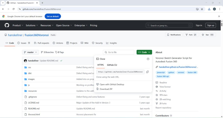
.jpeg)
Using emboss it is then added to the table top.
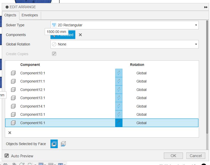
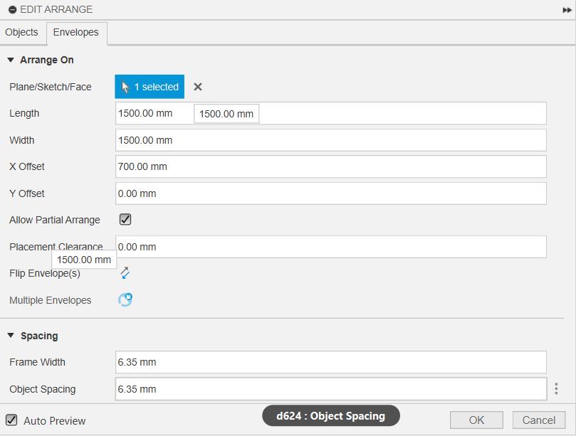
Arranging the parts
I opened the Arrange tool from the Solid → Modify menu, and in the Envelope section, I directly entered the width and height of my material sheet — this defined the area for arranging. Then, I selected all the objects I wanted to arrange and added them under the Objects section. o avoid the parts being too close to each other, I also specified the object spacing value.
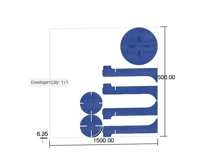
The arranged objects are then projected. Then I right clicked the projected sketch and exported it as dxf file.
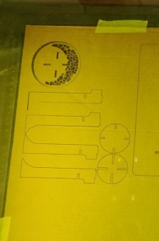
Before cutting it in the workpiece, the model was lasercut in a cardboard.I used a ratio calculator to scale down the design inorder to make a small model of the same.
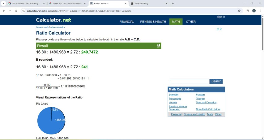
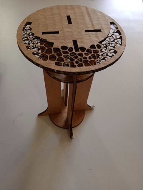
The design is assembled projected and exported as dxf and opened in Inkscape. The height of the canvas is adjusted with the value from ratio calculator in inkscape.The design underwent lasercuting.The result came out pretty well.
Mistakes:
- When I projected the sketch, the table top sketch got projected two times which resulted in two passes in laser cutter.
- After lasercutting it is found that the spacing between two patterns is very thin. In cardboard the structures will break. I couldn't engrave it as I was planning to add pockets in the bottom part of table top.
Milling
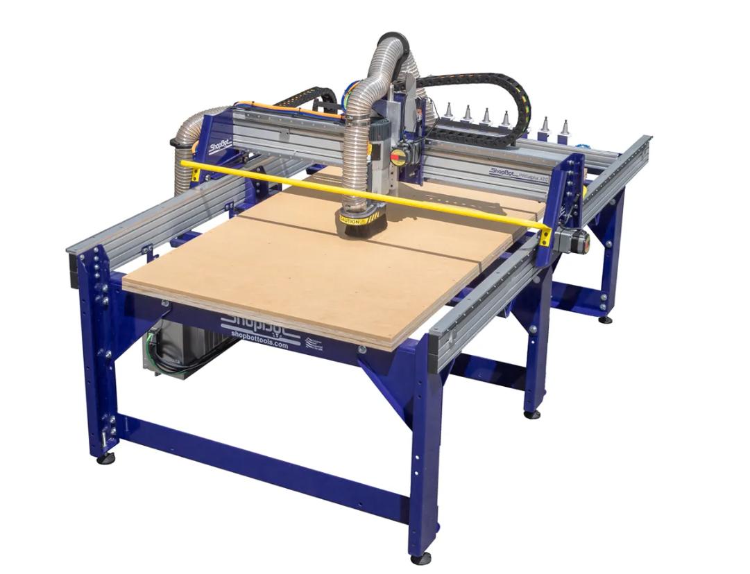
Shopbot PRSAlpha 96
I used the ShopBot PRSalpha 96 CNC router, a high-performance machine known for its speed, precision, and ability to handle full-sized plywood sheets. It supports both 2D and 3D cutting, making it suitable for creating intricate joinery and detailed designs. The PRSalpha series is widely used in fabrication labs and workshops due to its powerful motors, accuracy, and reliability. It can cut a variety of materials including wood, plastic, composites, and soft metals, making it ideal for applications such as furniture making, prototyping, signage, and custom fabrication. The "96" in its name refers to its 96-inch (8-foot) cutting bed, which allows for processing large-format materials with ease.
I continued my designing with out voronoi patterns.I exported the file to vcarve
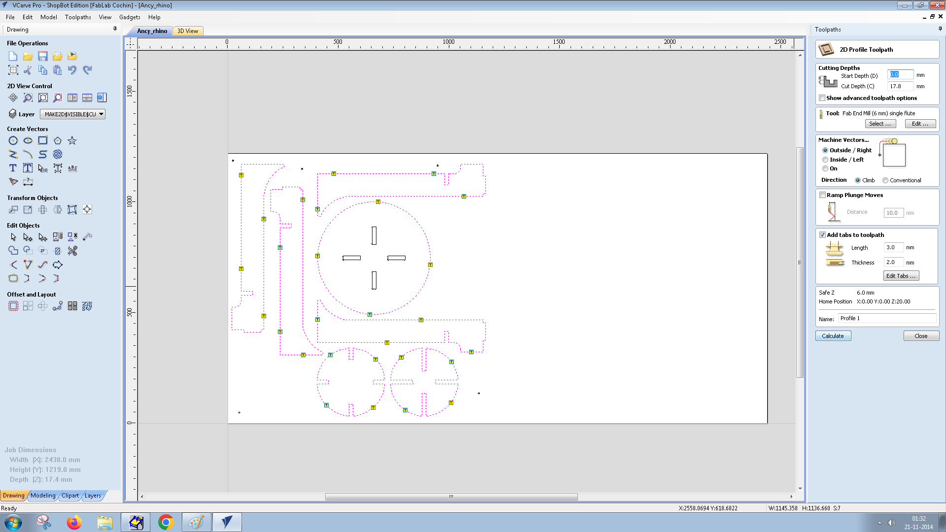
VCarve
VCarve software by Vectric is CAD/CAM (Computer-Aided Design/Computer-Aided Manufacturing) software used for creating 3D carvings from 2D images.
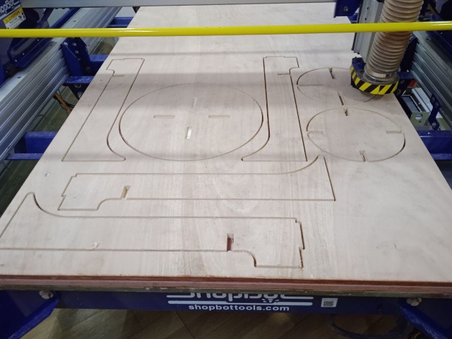
Placing plywood in shopbot
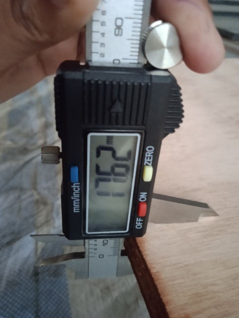
Initially I measured the thickness of plywood and the average value was taken as 17.4mm. From group assignment the clearence value was found as 0.2mm
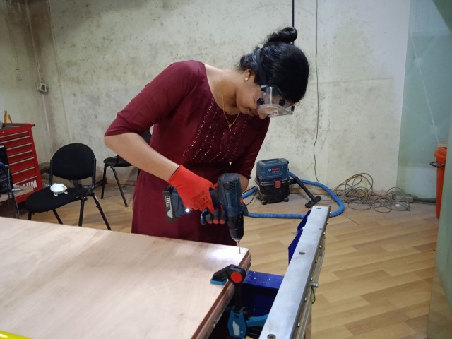
Placed the plywood sheet on the ShopBot bed.Used clamps and nails to hold it firmly in place and prevent any movement during cutting.
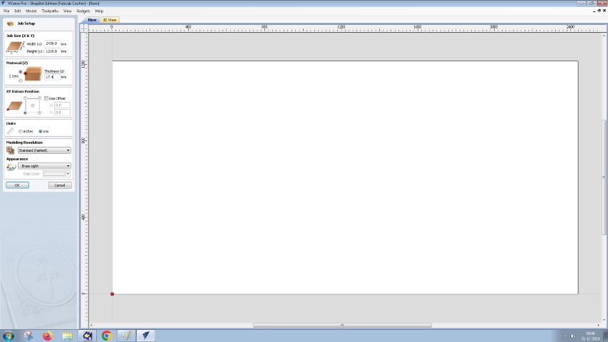
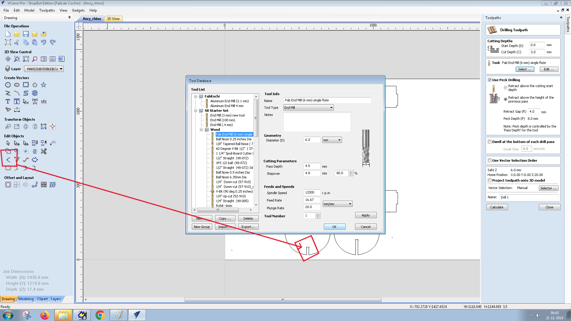
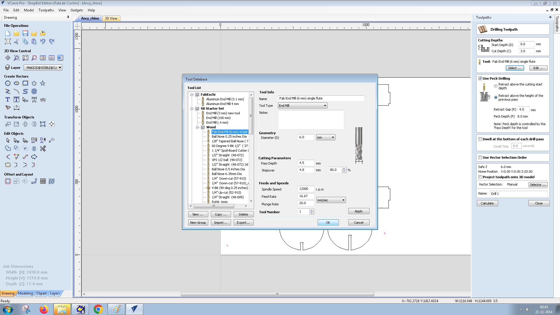
Open VCarve the length, width and thickness values are entered.I opened my file in it.
Adding Dogbone
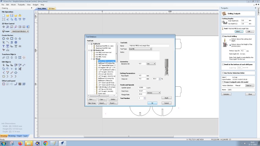
I looked for inside corners where two lines met at 90°—these were usually the joints where other parts would slot in. At the top of VCarve, I clicked on "Gadgets" → "Fillet" → "Dogbone Fillet". In the dogbone dialog box, I set the tool diameter to match the end mill I was using (6 mm). I chose the fillet type as "Dog-Bone" and selected the corner style as "Inside" for the internal corners. Then, I clicked on each internal corner where I wanted to add dogbones. VCarve automatically modified the corners with a circular overcut based on my tool size.
Setting the tool paths
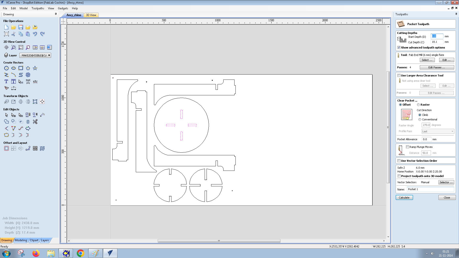
After making necessary changes the file is fed to shopbot software.
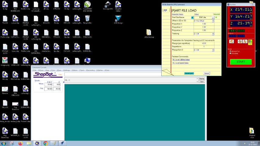
We have to calibarate x,y and z axis, afterwhich the start button in the window is pressed to operate
Mistakes: Initially when the program is fed, a window opens. It says to start spindle and click OK. Before starting the spindle I clicked OK.Friend pushed emergency button.If we operate before starting spindle the spindle will break.
Assembly
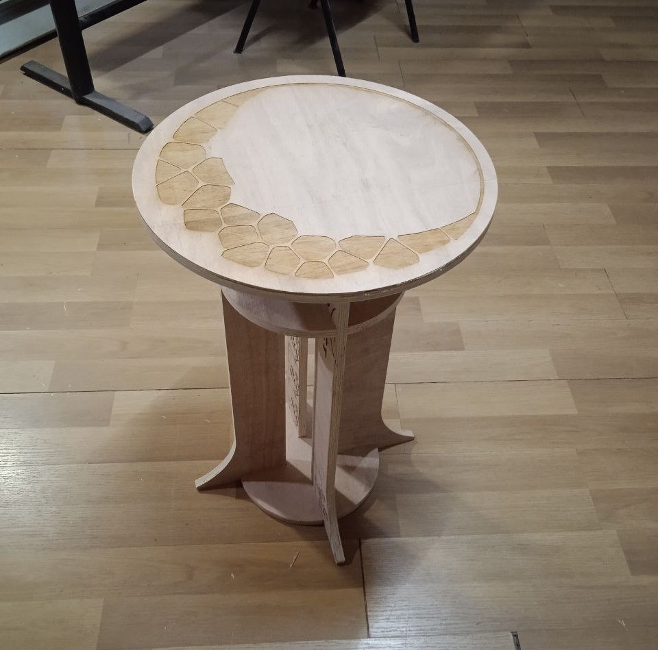
After CNC cutting, post-processing involves enhancing or modifying the cut pieces for functional or aesthetic reasons. This can include surface finishing, cleaning, deburring, or applying coatings like paint.Then assemble the parts together.Here is the final result.
.jpg)
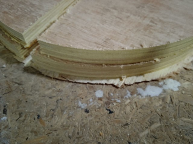
mistakes:Because of the variation in thickness, someparts didn't came as clean cut.
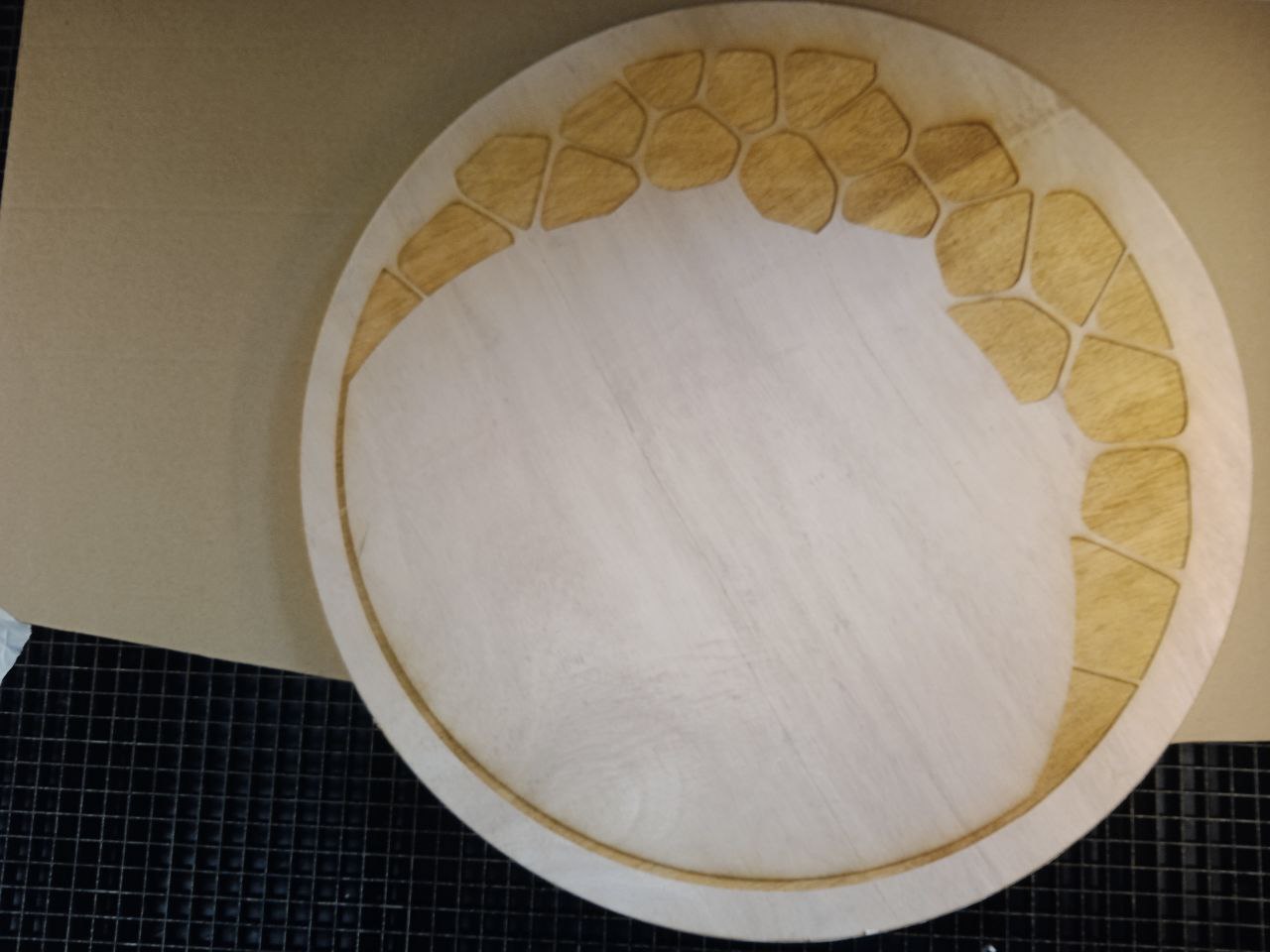
The table was plain and I wanted to continue with my Idea of adding patterns in it. Instructors told me that it is possible to engrave the patterns using laser cutter.
A test cut was made in a small piece of plywood
.jpeg)
From analysing the test cut I chose power as 90%, speed 20 and number of passes as 2.I cut the outerpart of the table in cardboard for reference and placed the table top inside it.
.jpg)
.jpg)
And the result.
In molding and casting week, I plan to add resin and give a it a final finishing.
Conclusion
This week’s work on computer-controlled machining provided valuable hands-on experience with CNC operations, safety protocols, and design iteration. From initial sketching to final assembly, I explored parametric design, laser cutting for prototyping, and CNC milling for fabrication. The process highlighted the importance of precise measurements, toolpath optimization, and troubleshooting errors, such as unexpected double projections and material thickness variations. Despite some challenges, the final coffee table successfully came together, with additional engraving added for aesthetics. This project reinforced my understanding of digital fabrication workflows and practical problem-solving.
files
Design filesHeroshot