Objectives
Group assignment: - Use the test equipment in your lab to observe the operation of a microcontroller circuit board
Individual assignment: - Use an EDA tool to design a development board that uses parts from the inventory to interact and communicate with an embedded microcontroller extra credit: try another design workflow extra credit: design a case for it
Group Assignment
In our group assignment, we learned how to use various essential lab instruments for testing and analyzing electronic circuits. We worked with the ZOYI ZT301 digital multimeter to measure voltage, current, resistance, continuity, and diodes. We used the GW Instek AFG-2125 function generator to produce different waveforms and observed how changing frequency affected an SMD LED's blink rate. With the GW Instek GPD-3303D bench power supply, we tested voltage and current outputs on a resistor-LED circuit, exploring its modes and safety features. Using the OWON TAO3104A oscilloscope, we analyzed signal waveforms, calibrated probes, and captured PWM signals from a MEMS microphone. Finally, we used the Saleae Logic Pro 8 logic analyzer to examine digital I2C signals from a XIAO RP2040 microcontroller, gaining insights into protocol decoding and signal timing.
 group assignment page
6. ELECTRONICS DESIGN
Electronic components
Electronic components are the fundamental building blocks of electronic circuits, designed to control the flow of electricity in a system. They can be active (such as transistors and diodes) or passive (such as resistors and capacitors), each serving a specific function within a circuit. When connected on a printed circuit board (PCB), these components work together to form functional electronic devices.
Active and passive components
Active and passive components are the two main types of electronic components used in circuits. Active components require an external power source to function and can amplify, switch, or generate electrical signals. Common examples include transistors, diodes, and operational amplifiers. In contrast, passive components do not need an external power source and mainly resist, store, or control the flow of electricity without amplification. Examples of passive components include resistors, capacitors, and inductors. Both active and passive components are essential for building and operating electronic circuits.
source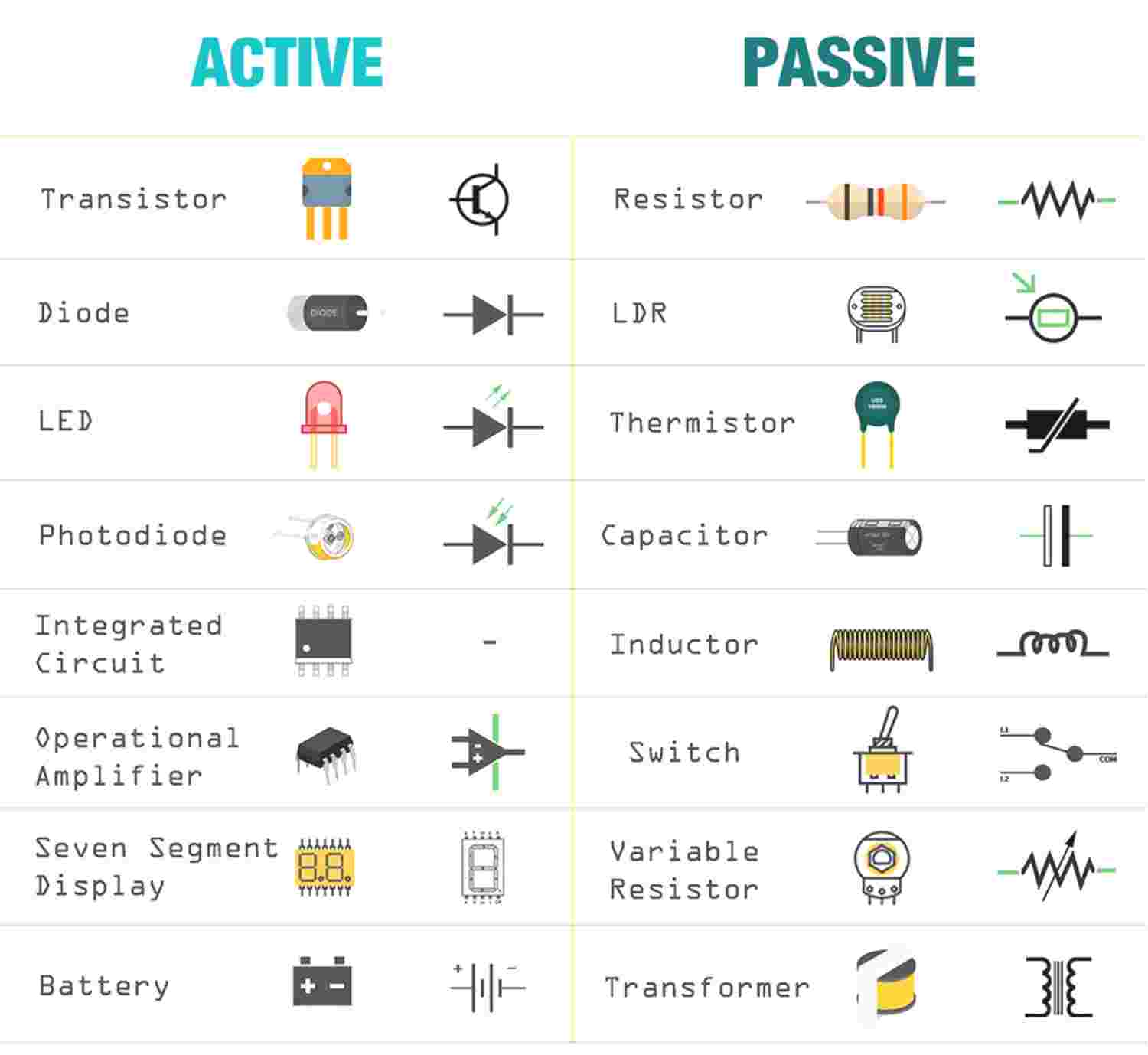 image
image
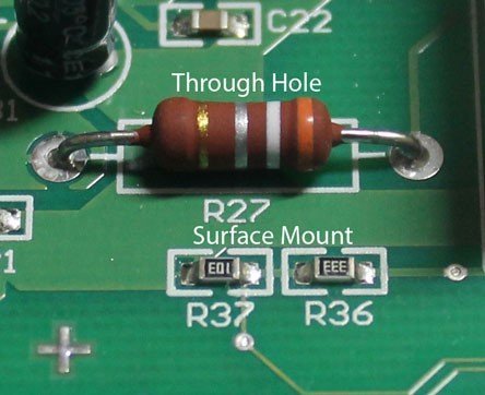
Resistor
A resistor is a passive electronic component that limits or regulates the flow of electric current in a circuit. It is commonly used to control voltage levels, divide currents, and protect components from excessive current. Resistors are made from materials like carbon, metal film, or wire-wound ceramics, depending on their application. The resistance value is measured in Ohm (Ω). They come in different types, including fixed, variable (potentiometers), and surface-mount resistors (SMRs) for compact circuits.SMD (Surface Mount Device) resistors are small, flat components designed for direct mounting onto the surface of a PCB, making them ideal for compact, high-density circuits. In contrast, through-hole resistors have leads that pass through holes in the PCB and are soldered on the other side, providing strong mechanical bonds and easier handling.
 image
image
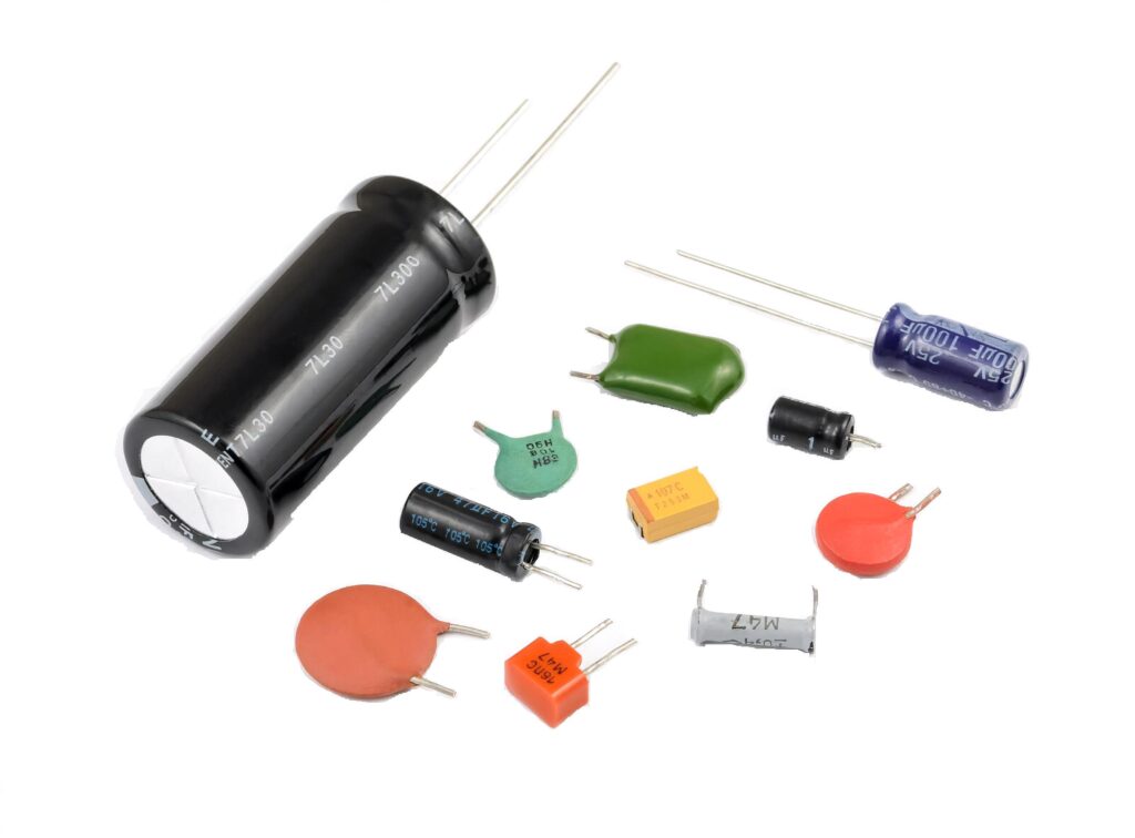
Capacitor
A capacitor consists of two or more parallel conductive plates that are electrically separated by an insulating material called the dielectric. These plates do not touch each other, and the dielectric can be made of air, waxed paper, mica, ceramic, plastic, or a liquid gel (as found in electrolytic capacitors). When connected to a voltage source, a capacitor stores electrical charge on its plates, creating an electric field between them. The ability of a capacitor to store charge is measured in farad (F), the SI unit of capacitance, where 1 farad (F) = 1 coulomb per volt (C/V). Since capacitors do not allow direct current (DC) to pass, they are widely used for energy storage, filtering, and signal processing in electronic circuits.
 Image
Image
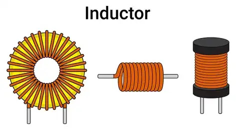
Inductor
An inductor is a passive electronic component that temporarily stores energy in a magnetic field when an electric current passes through its coil. It consists of two terminals and a coil of insulated wire, which can either loop through the air or wrap around a core material that strengthens the magnetic field. Inductors play a key role in managing fluctuations in electrical current within a circuit. The standard unit of inductance is the henry (H).
 image
image
Transistor
A transistor is a semiconductor device that plays a vital role in amplifying or switching electronic signals and electrical power. It is composed of three layers of semiconductor material, where the flow of current or voltage between two layers is controlled by applying an electric current or voltage to the third layer. As a fundamental component in modern electronics, transistors are integral to the operation of devices such as radios, computers, and complex integrated circuits. They are available in different types, including bipolar junction transistors (BJTs), field-effect transistors (FETs), and MOSFETs, each designed for specific applications based on its distinct properties and working principles.
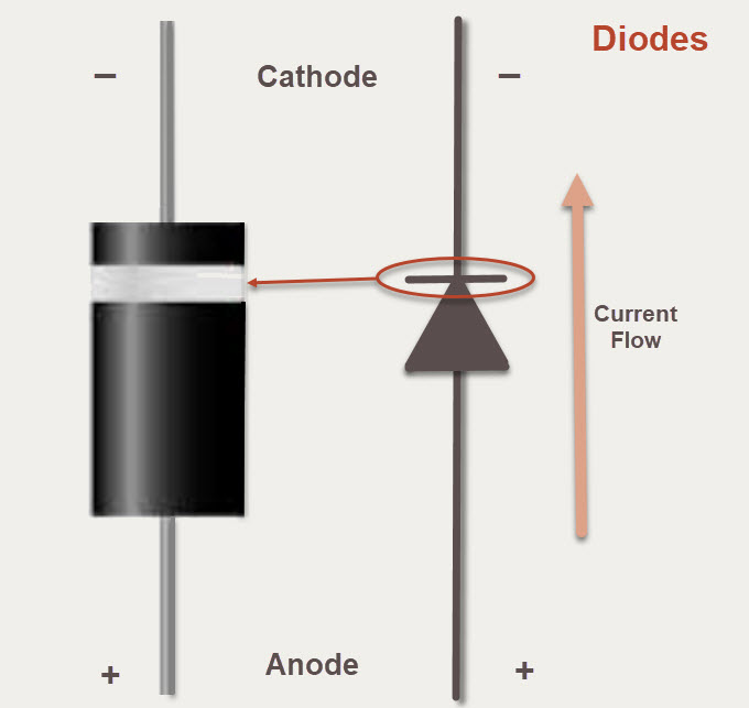
Diode
A diode is a semiconductor device that primarily allows current to flow in one direction while blocking it in the opposite direction. This property makes diodes essential for converting alternating current (AC) to direct current (DC), protecting circuits, and enabling various electronic functions.Diodes operate in two modes:
- Forward Bias: When the anode is at a higher potential than the cathode, the diode conducts electricity.
- Reverse Bias: When the cathode is at a higher potential, the diode blocks current, acting as an insulator.
- Rectifier Diode : Used for converting AC to DC.
- Zener Diode : Designed to operate in reverse bias and regulate voltage.
- Light Emitting Diode (LED) : Emits light when forward-biased.
- Photodiode : Converts light into electrical current.
 image
image
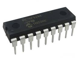
Integrated circuits (IC)
Integrated circuits (ICs) are essential components in modern electronics, consisting of resistors, capacitors, inductors, diodes, and transistors fabricated onto a single semiconductor chip, usually made of silicon. These components are interconnected to perform specific functions such as amplification, signal processing, computation, and power management. Since the semiconductor material is delicate, ICs are housed in protective plastic, ceramic, or metal packages with metal pins for easy connection to circuit boards. ICs can be categorized into analog, digital, and mixed-signal types, enabling compact, efficient, and reliable electronic devices.
 Image
Image
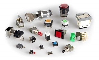
Switch
A switch is an electrical or electronic device that controls the flow of current in a circuit by connecting or disconnecting it. Switches can be broadly classified into mechanical and electronic (solid-state) switches. Mechanical switches, such as push buttons, toggles, and rotary switches, operate through physical movement and can be categorized based on actuation method, contact configuration, poles and throws, and operating states. Electronic switches, like transistors, MOSFETs, and thyristors, have no moving parts and use semiconductor technology to switch circuits efficiently, making them ideal for applications in automation, motor drives, and HVAC systems.
 image
image
KiCad
KiCad is a free, open-source Electronic Design Automation (EDA) software suite used for creating schematics and designing printed circuit boards (PCBs). It provides tools for schematic capture, PCB layout, circuit simulation, and generating manufacturing files such as Gerber files. KiCad also includes features like 3D modeling, bill of materials (BOM) generation, and engineering calculations, making it a powerful tool for electronics design.
Go to the official KiCad website. Choose your operating system (Windows, macOS, or Linux). Download the installer for the latest stable version.Run the installer and follow the installation instructions.I downloaded and installed KiCad. Now open KiCad . File → New Project . Name your project
.jpeg)
Snap EDA
SnapEDA is a free online platform that provides schematic symbols, PCB footprints, and 3D models for electronic components, which can be used in EDA tools like KiCad. Instead of manually creating footprints and symbols, users can simply search for a component on SnapEDA, download the KiCad-compatible files, and integrate them into their schematic and PCB layout. In place symbol tool select for the microcontroller you want to work with.I searched for ATTINY 412, which wasn't available in the library. So i had to manually added it. I used snap eda. Pins were assigned using datasheet. Symbols and footprint were created and downloaded.The zip file is then extracted.
.jpeg)
Preference → Manage symbol libraries. From folder add your symbol library to the table.
.jpeg)
In the same way , Preference → Manage footprint libraries. From folder add your footprint library to the table.
.jpeg)
Using the FabLab Library in KiCad
KiCad is an open-source electronics design automation (EDA) tool used to create schematics and PCB layouts. In the context of Fab Labs, we use KiCad along with the FabLab Library to streamline the design process.
The FabLab Library is a curated collection of components commonly used in Fab Academy and Fab Lab projects. It includes footprints and symbols for microcontrollers, sensors, connectors, and other parts that are compatible with standard Fab Lab fabrication workflows.
To add git lab kicad library, copy the SSH key. Create a local folder. Clone it inside the folder.
.jpeg)
.jpeg)
Design 1
Before adding components to my design, I referred toFabStash - a website listing all components available in the Super Fab Lab Kochi inventory and reviewed the relevant datasheets
Schematic editor
Instructor Midhun demonstrated how to use KiCad for PCB design with a practical example. We followed along using the component values and design specifications provided by him. In KiCad we have two editors, schematic editor and pcb editor. Open schematic editor.
.jpeg)
Add Components
Wire the Components
Add Power Symbols
Add Values and Labels
.jpeg)
voltage regulator
In the voltage regulator circuit I designed, a linear voltage regulator was used to convert an external input voltage to a stable 5 V output. To ensure reliable operation and reduce voltage fluctuations, two capacitors were added: a 10 µF capacitor at the input to smooth out any noise or ripples from the power source, and a 100 µF capacitor at the output to stabilize the regulated voltage and provide a quick response to load changes. These capacitors help improve the performance of the regulator by minimizing transient voltage spikes and ensuring a steady 5 V supply to downstream components.
.jpeg)
ATTINY 412
I used the ATtiny412 microcontroller in my circuit.
.jpeg)
UART
UART stands for Universal Asynchronous Receiver/Transmitter. It is a serial communication protocol used to exchange data between digital devices, such as microcontrollers, sensors, and computers. No clock signal is shared between the sender and receiver. Instead, both devices must agree on a baud rate.
Two main lines:
.jpeg)
switch
I added a switch to my circuit and connected a resistor between the input pin and 5 V, which made it a pull-up resistor configuration. When the switch was open, the resistor kept the pin at a HIGH state (5 V). When I pressed the switch, it connected the pin to ground, pulling it LOW. The resistor was important because it prevented the pin from floating when the switch was not pressed, ensuring stable and reliable digital readings.
.jpeg)
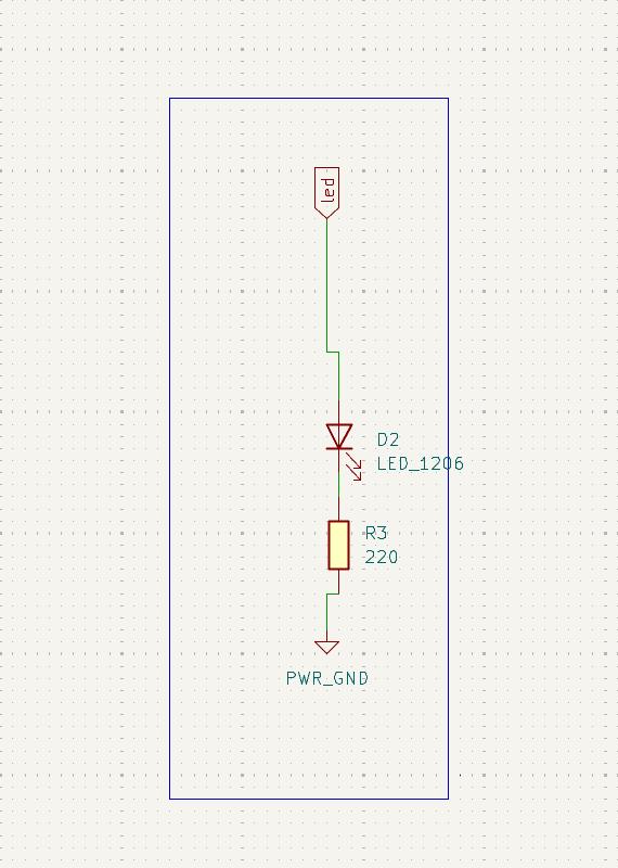
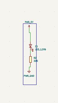
LED
I placed a red LED in my circuit and powered it with 5 V. I added a 220 Ω resistor in series with the LED to limit the current flowing through it. Without the resistor, the LED could have drawn too much current, potentially damaging itself or the microcontroller. The resistor ensured that the LED operated safely within its current rating, providing stable and reliable illumination. For a standard red LED, the forward voltage is usually around 2 V, and the safe operating current is about 20 mA. so the voltage that needs to drop across the resistor is 3so the voltage that needs to drop across the resistor is 3V. From ohm's law the value of resistor found to be 150 ohm. And we use 220 ohm as standard.
Power LED
I added a power LED to indicate when the circuit was powered. It was a red LED connected to the 5 V output of the microcontroller. I placed a 220 Ω resistor in series with the LED to limit the current and prevent damage.
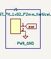
External Voltage
I connected the external voltage to the circuit using a 1x02 JST vertical male connector.
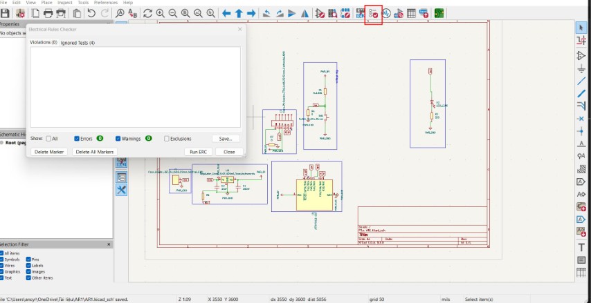
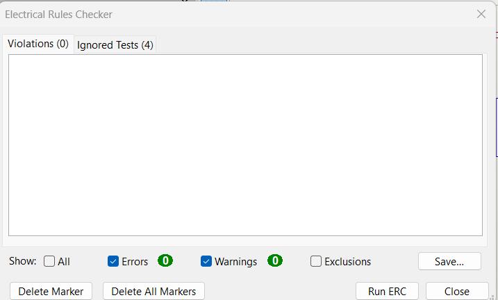
ERC checking
ERC stands for Electrical Rules Check, and in KiCad's Schematic Editor, it checks your circuit for common electrical mistakes that could cause problems when building or simulating the board.
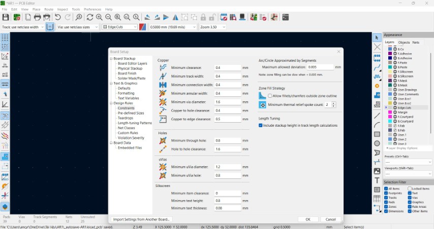
PCB editor
To work with pcb editor first we need to define designrules. Design rules are used for preventing short circuits and interference, ensuring manufacturability, setting standards for trace widths, clearances, and layers. Open pcb editor. From file -> board setup -> Design rules
Transfer to PCB Editor
Arrange Components
.jpeg)
The components are reaaranged. to track route simply use shortcut X or we can find it in the right pannel. select edge cut and draw the shape of our pcb.
.jpeg)
.jpeg)
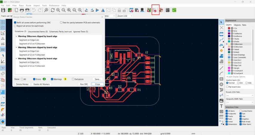
DRC checking
DRC, or Design Rule Check, is used in the PCB Editor to automatically check if your PCB layout follows the design rules you've set - such as trace width, spacing, and via sizes. It's one of the most important steps before manufacturing your board.
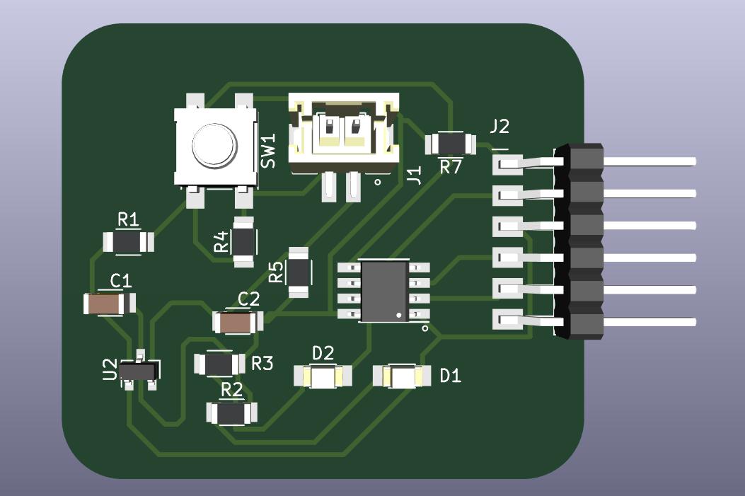
3D viewer
From the 3d viewer in the top panel we get the 3d model of our PCB.
Design 2
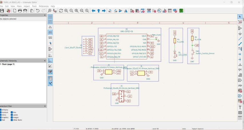
Schematic Editor
I used XIAO ESP32 C6 microcontroller. For that a new file is created. The symbol and foot print of the same wasn't available in KiCad. So I manually added the symbol and foot print libraries.
Preference → Manage symbol libraries. From folder add your symbol library to the table.
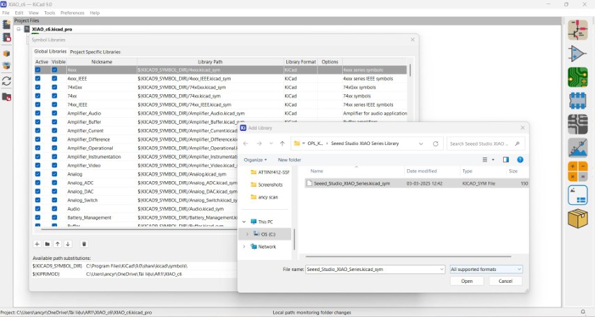
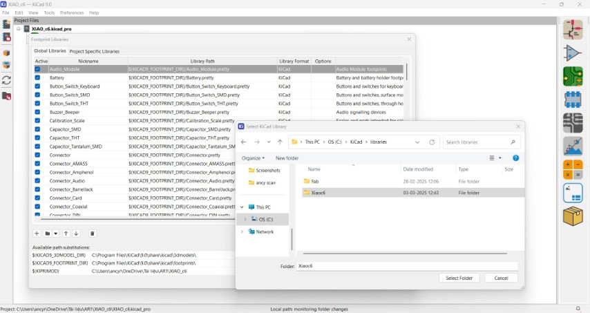
In the same way , Preference → Manage footprint libraries. From folder add your footprint library to the table.
I made the connection diagram in schematic editor
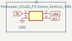
IIC
IIC (also written as I²C, pronounced "I-squared-C") stands for Inter-Integrated Circuit. It’s a communication protocol used to allow multiple digital devices (like microcontrollers and sensors) to communicate with each other using just two wires.
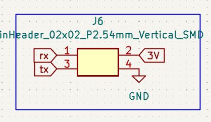
UART
Two main lines:
Switch
Switch has a pull up resistor.
.jpeg)
LED
.jpeg)
Connectors
Connectors are added to make all pins available for use.
.jpeg)
.jpeg)
XIAO esp32 c6
.jpeg)
ERC checking
PCB Editor
open PCB editor from file-> board setup -> design rules
.jpeg)
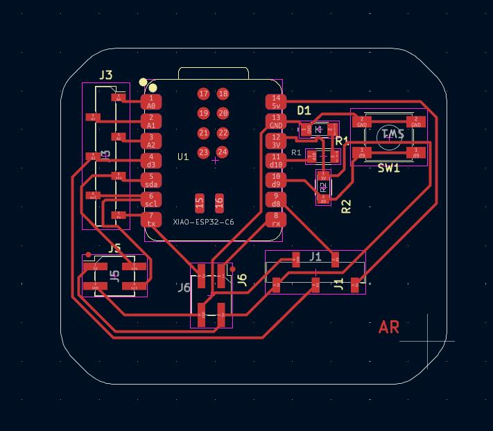
Now we have to arrange the components and track routes
pcb.jpeg)
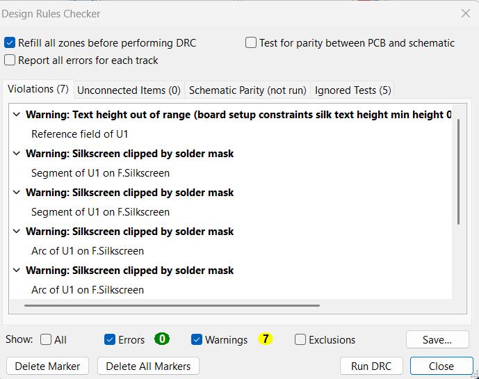
DRC checking
AS we don't have any silkscreen the warnings were ignored.
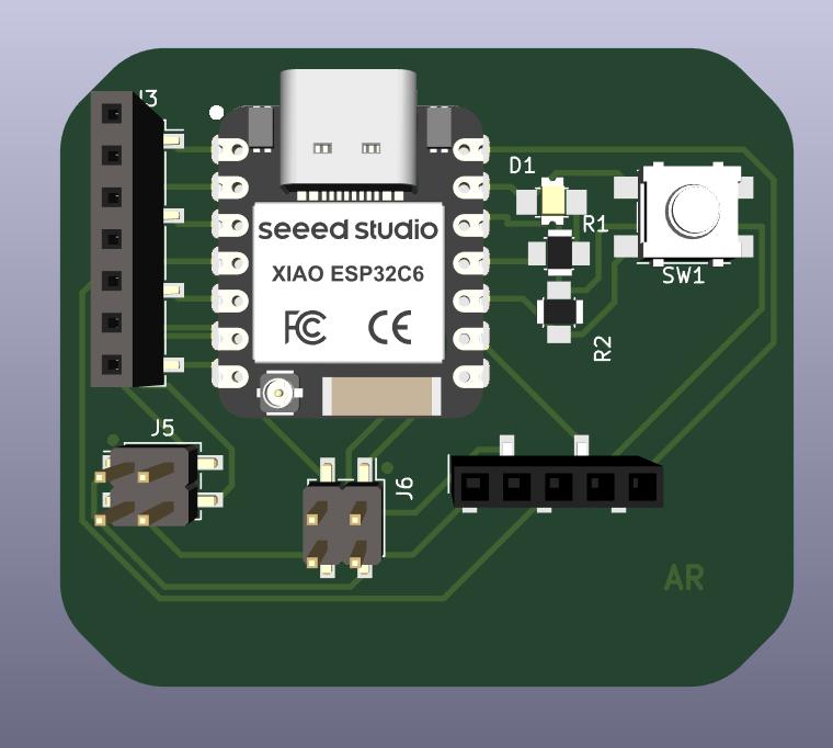
3D viewer
In 3D viewer we can see the 3d view of our PCB.
Exporting gerber
We can export the file as gerber. From file -> fabrication output -> gerber
.jpeg)
click on plot the click generate drill files.
.jpeg)
We can view the file using an online gerber viewer. Extract gerber file in the folder and upload in the online gerber viewer.
.jpeg)
Mistake :- The USB part of XIAO was supposed to be placed at the edge of PCB as it will help to plug in easily.
Designing A case for PCB
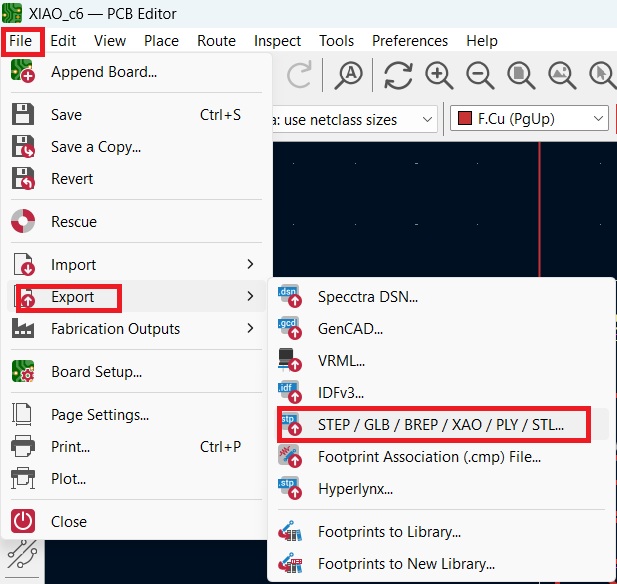
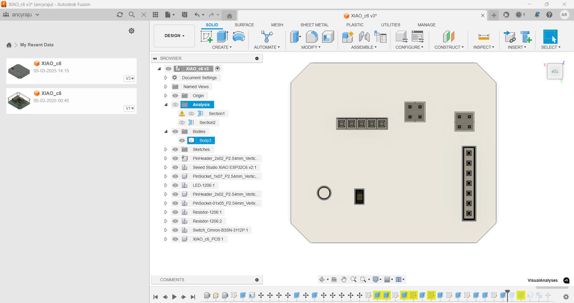
I tried to design a case for the PCB in fusion. I exported the file in pcb editor as step file and opened it in fusion.
To import file in fusion, open file -> open.

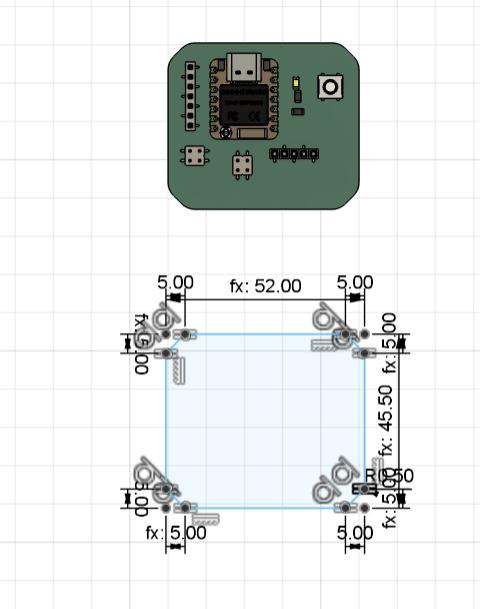
I measured the length and width of the PCB and created a parametric sketch with those dimensions.
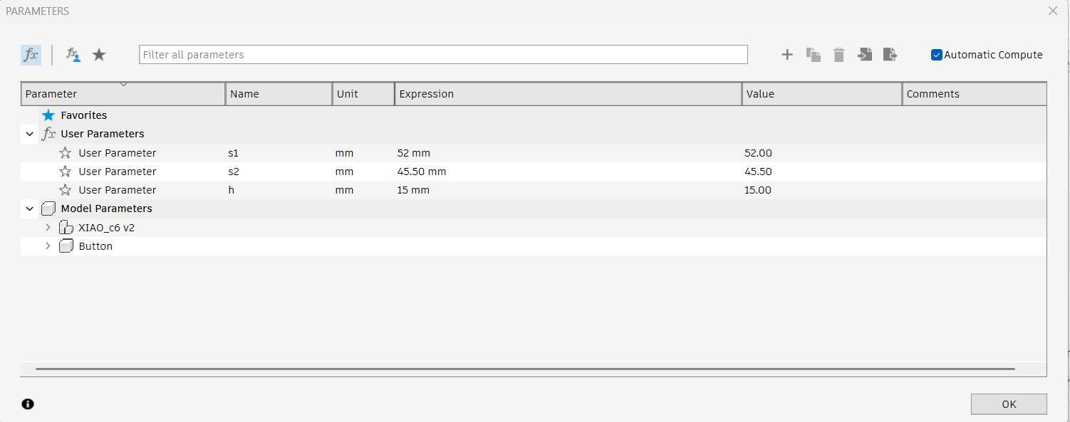
The height was set to 15 mm, so I extruded a rectangle of 52 mm length and 45.5 mm width to that height.
Then, I applied the shell function with a thickness of 1 mm to hollow out the body. Using measurements from the protruding connectors and pin headers, I made precise cutouts in the case to accommodate them. I also projected the position of the USB port of the XIAO board and cut out that section from the case, ensuring the USB cable could be connected easily.
Files
zipfileHeroshot