5. 3D PRINTING AND SCANNING
Objectives
Group assignment: - test the design rules for your 3D printer(s)
Individual assignment: - design and 3D print an object (small, few cm3, limited by printer time) that could not be made subtractively - 3D scan an object (and optionally print it)
Group Assignment
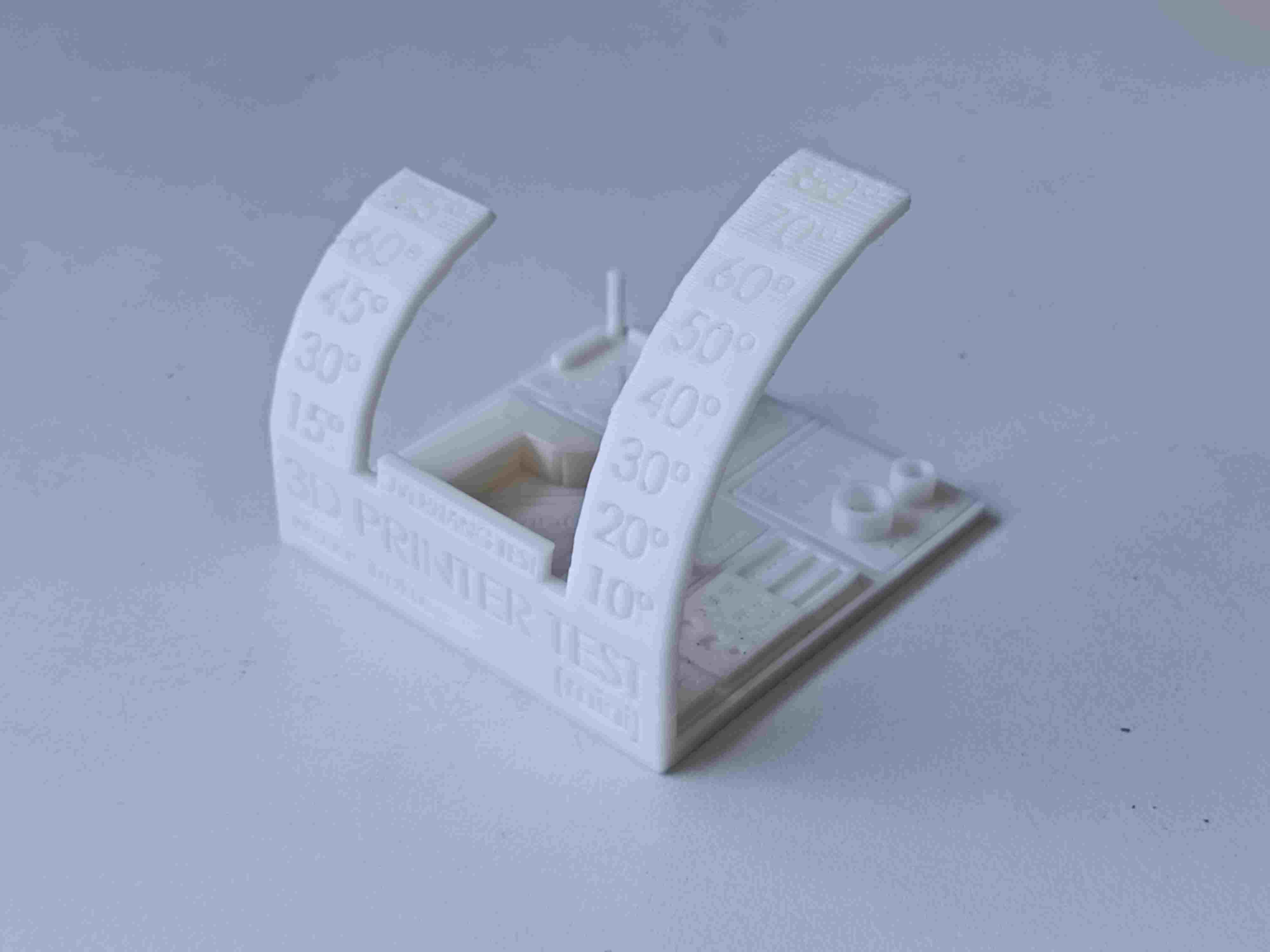
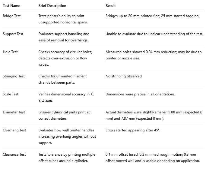
As part of our group assignment, we downloaded an all-in-one test model and 3D printed it. One of the models was specifically used for a clearance test. After printing, we analyzed the model and recorded the measured values for future reference. This hands-on experience helped us learn about the 3D printing process, different types of 3D printing technologies, and important safety measures when operating the machines. Through this assignment, I had the opportunity to explore and learn more about the Bambu Lab A1 3D printer, which was the main machine I focused on. I was impressed by how user-friendly and efficient it was—features like automatic bed leveling and multi-color printing made the process much smoother than I expected. I also gained valuable insights from my teammates’ research on other 3D printing technologies, which helped broaden my understanding of the different machines and methods available.
To know more, visit group assignment page
3D PRINTING
3D printing, also called additive manufacturing, is a technique for creating three-dimensional objects by layering materials based on a digital design. Unlike traditional manufacturing, which involves cutting or molding, 3D printing builds objects from the ground up, reducing waste and enabling intricate designs.
How it works ?
- Designing the Model
- A 3D object is created using computer-aided design (CAD) software or scanned with a 3D scanner.
- The design is then converted into a stereolithography (STL) file or another format suitable for 3D printing.
- Slicing the Model
- The 3D model is digitally divided into thin layers using slicing software.
- The sliced file is sent to the 3D printer for fabrication.
- Printing Process
- The printer builds the object layer by layer, following the sliced model’s instructions.
- Various materials can be used, including plastics, resins, metals, ceramics, and even biological substances.
Common printing techniques include:
- Fused Deposition Modeling (FDM) – Melts and extrudes plastic filament.
- Stereolithography (SLA) – Uses UV light to cure liquid resin.
- Selective Laser Sintering (SLS) – Fuses powdered material using lasers.
Post-Processing
- After printing, the object may require cleaning, curing, or additional finishing, such as sanding or painting, to enhance its appearance and functionality.
Additive manufacturing vs Substractive manufacturing
Subtractive manufacturing shapes an object by removing material, while additive manufacturing constructs it by gradually adding layers of material. Subtractive methods have been in use for a longer time and are typically faster, making them well-suited for high-volume production. In contrast, additive manufacturing allows for the creation of intricate designs, such as hollow or nested structures, which are challenging or even impossible to achieve with subtractive techniques.
Bambu Lab A1
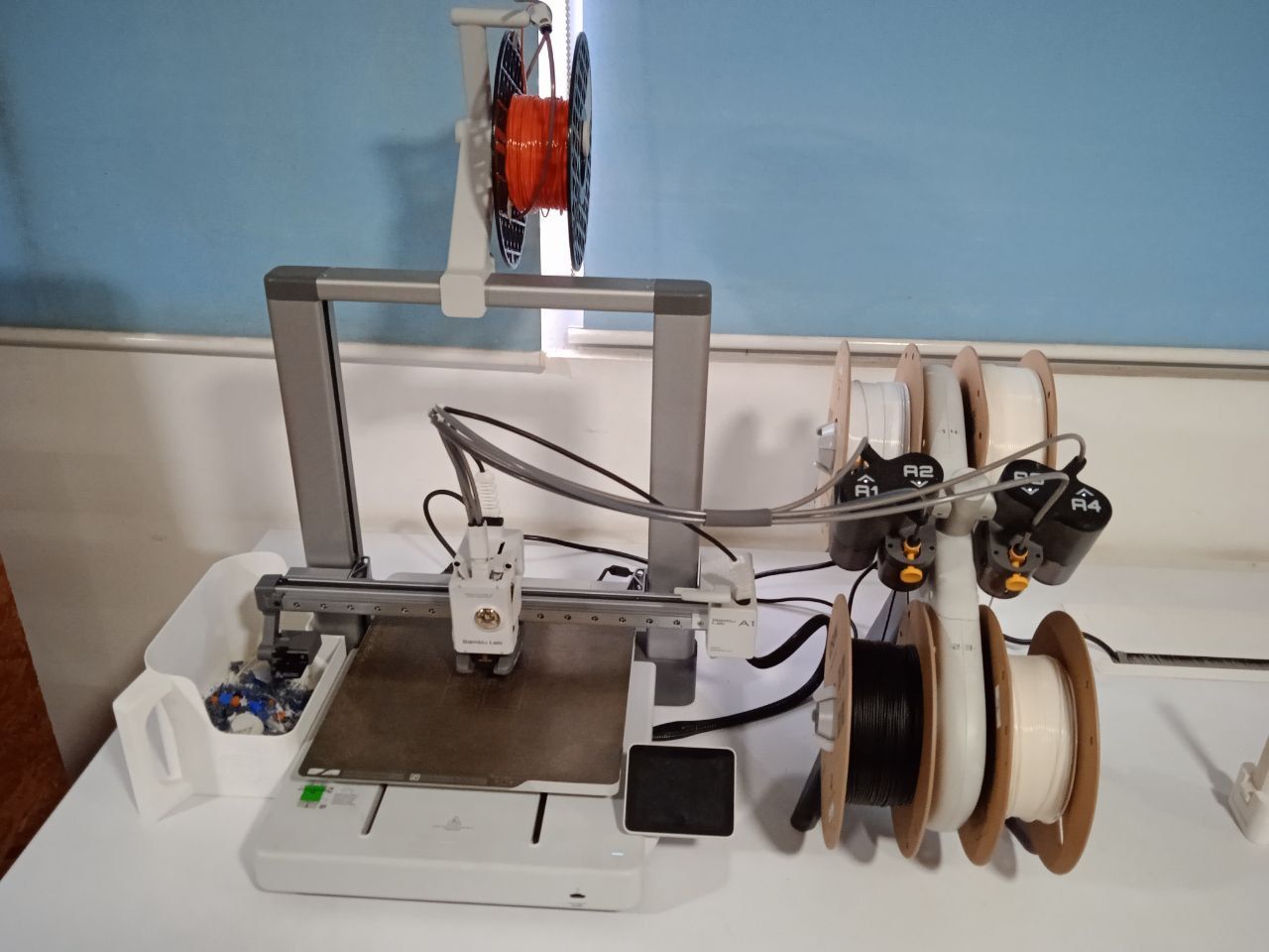
The Bambu Lab A1 is a high-speed Core XY 3D printer , offering smart automation features like auto Z-offset, auto flow calibration, auto belt tensioning, and real-time flow rate compensation.
The A1 features several smart automation functions that simplify the printing process, including:
- Auto Z-Offset: Automatically calibrates nozzle height with precise probing, removing the need for manual bed leveling.
- Auto Flow Dynamics: Calibrates pressure advance to improve extrusion accuracy and quality.
- Auto Belt Tension: Monitors and adjusts the tension of belts to ensure consistent motion and accuracy.
- Real-Time Flow Rate Compensation: Uses high-frequency sensors to adjust filament flow dynamically during printing.
- Auto Vibration Calibration: Tunes X and Y axis resonance to reduce vibration and enhance print quality.
- Auto Filament Loading: Allows for simple, one-touch filament changes.
Another highlight was the multi-color printing capability made possible with the optional AMS Lite system, allowing seamless color transitions in a single print job. The printer also includes safety and recovery features like filament run-out detection and power loss recovery, which add reliability to longer or unattended prints.
From a usability perspective, the A1’s touchscreen interface is intuitive and easy to navigate, and it supports both cloud-connected and offline LAN mode for privacy-conscious users. The build volume of 256×256×256 mm³ is ample for most desktop printing needs, and the machine supports a wide range of materials including PLA, PETG, TPU, and more.
Overall, I learned how modern 3D printers like the Bambu Lab A1 can automate much of the calibration and maintenance traditionally required, making high-quality printing more accessible and efficient.
Design 1
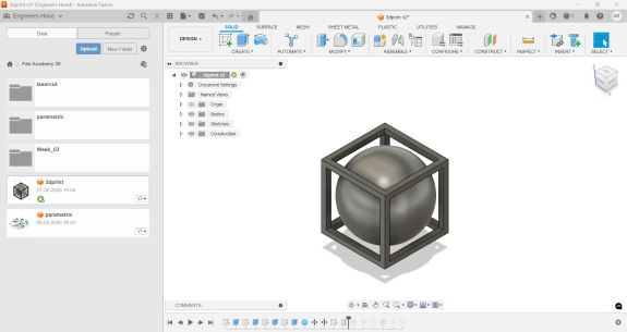
The design can be made substractively. I made a 3D model to explore how 3D printing works. To design the cube frame, I drew a 40mm square frame and extruded it. A 34mm square is cut out from all sides to make it a frame. The next part was to add a sphere. a sphere of diameter 45 mm is drawn and placed inside the cube frame using move tool as shown below.
 |
 |
The initial sketch for designing was done in fusion 360
The image is then exported as a step file. For the slicer, I downloaded Bambu A1 software
Bambu A1I opened the file in the software
For support I selected tree type. Infill was 15. To select infill, strength → infill. I selected 0.24 mm as layer height. Select slice plate. After making necessary changes select print plate. Select the 3d printer and connect. Once the calibration is complete, printing process will start.
Instructor told me that the design can be made substractively using CNC milling. So another design was sketched in fusion. I added a torous to make it a keychain.
Design 2
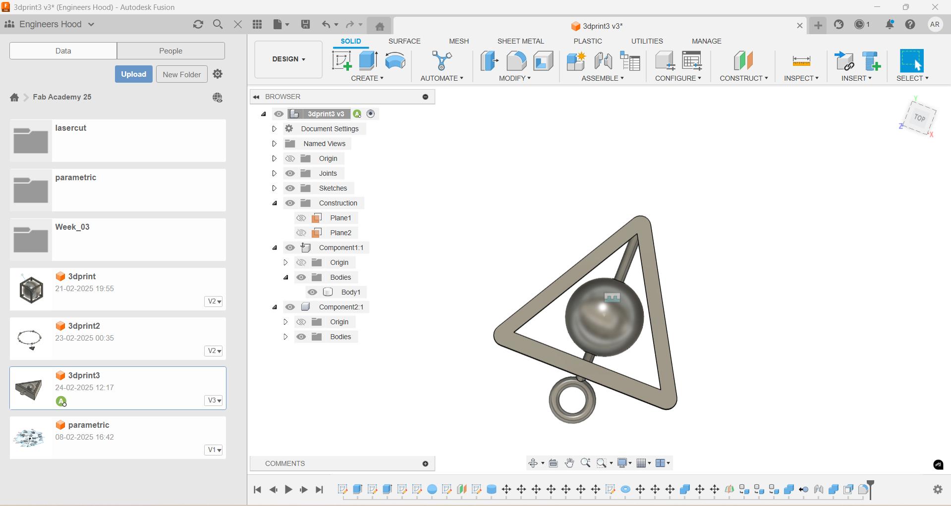
The design was inspired from harry potter logo. To create the 3D model, first i drew a 40 mm triangle. I extruded the triangle into 3d and cutout a 30mm triangle from it. A 15 mm diameter sphere and a 32 mm long rod is created. A hole is created in the sphere to allow the free motion of sphere through the rod. The same feature makes it hard to mill using a CNC machine and through substractive manufacturing. The components are then arranged accordingly and the edges of triangle is chamfered to get a good finish.
 |
 |
 |
Initial sketch was made in fusion 360.
The sketch is then exported as a step file
To export as step file, go to files -> export
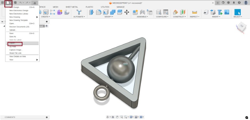
Then we will be provided with a lot of options. choose step files.
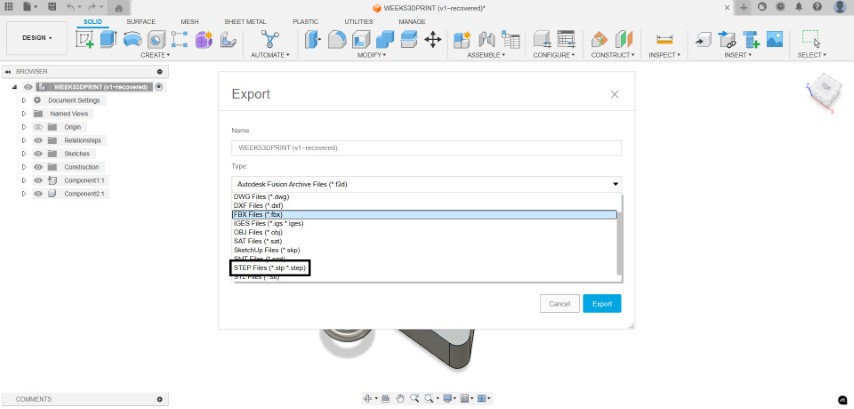
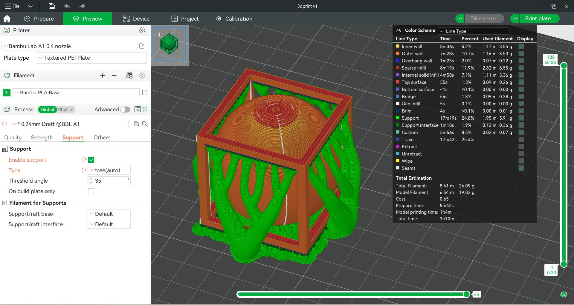
and opened in Bambu Lab A1 slicer
Bambu Studio
Bambu Studio is an open-source, cutting-edge, and feature-rich slicing software designed specifically for Bambu Lab 3D printers. It offers a project-based workflow, systematically optimized slicing algorithms, and an intuitive graphical user interface, providing users with an incredibly smooth and efficient printing experience.
This slicer is based on PrusaSlicer, but it has been heavily customized to support high-speed CoreXY motion systems and multi-material printing through the AMS (Automatic Material System). With these enhancements, Bambu Studio helps users unlock the full potential of their Bambu Lab printers while maintaining compatibility with advanced print settings, customizable supports, and fine-tuned control over print parameters.
Download bambu studio. Click on the exported step file. It will open in bambu slicer or you can open it from slicer.
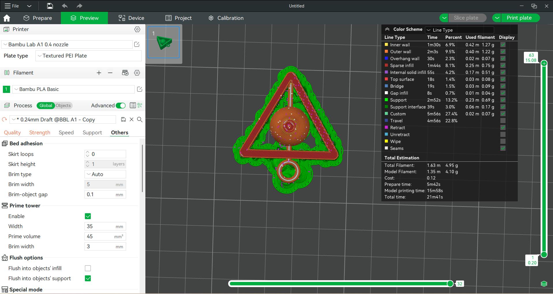
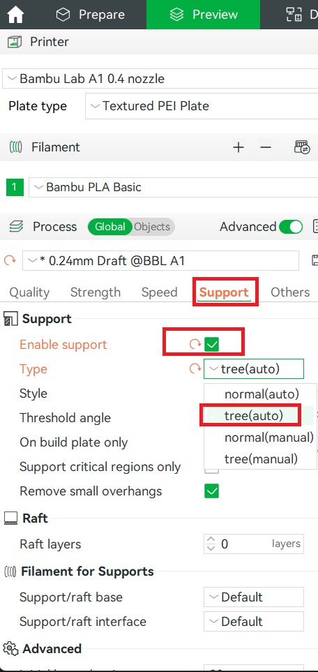
The support was selected as tree type and infill as 30. Random seam was selected.Layer height was selected as 0.24mm
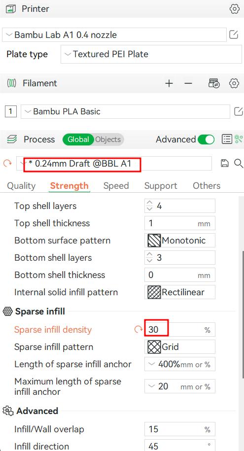
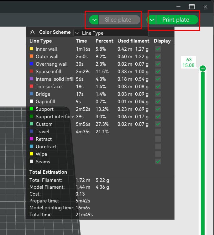
Slice the object
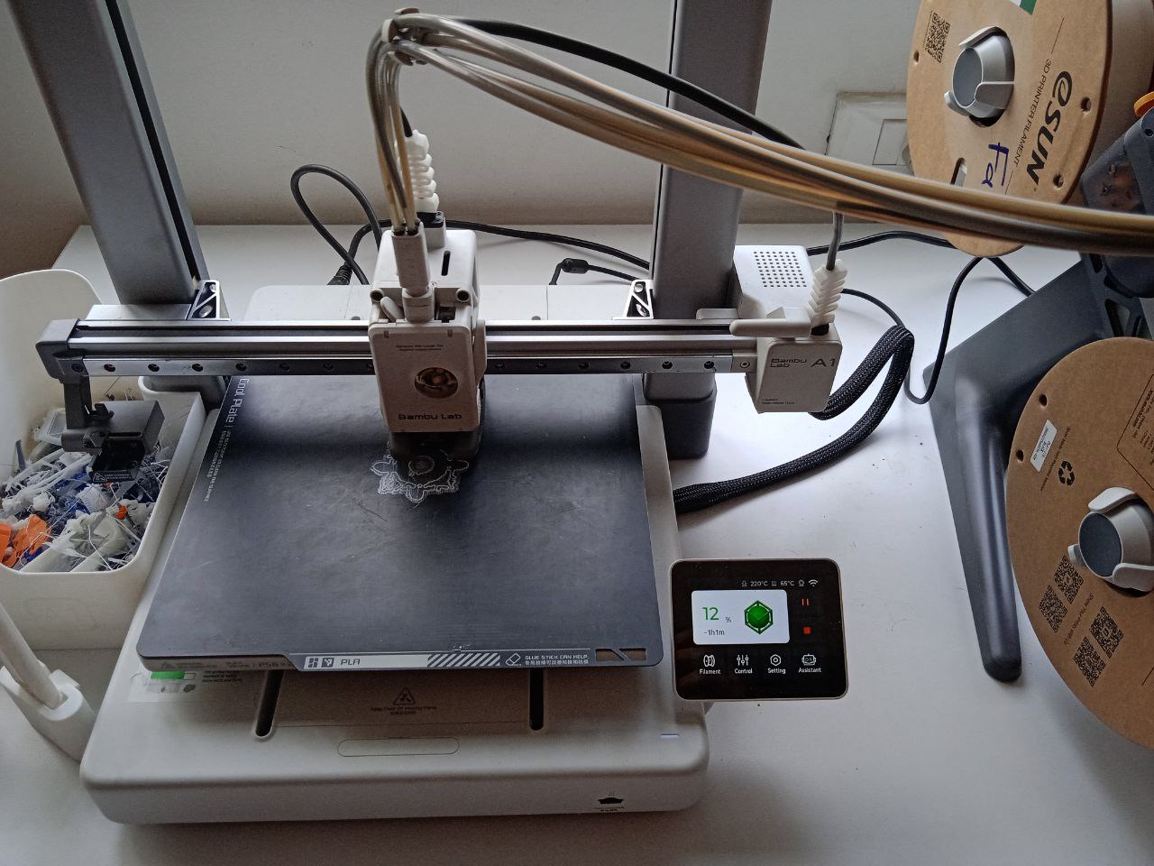
After making necessary changes, select print plate and select the printer in it. Select send. Then the job is fed to the printer
Then a window opens showing the printing page.The print status and camera feed can be seen on this page
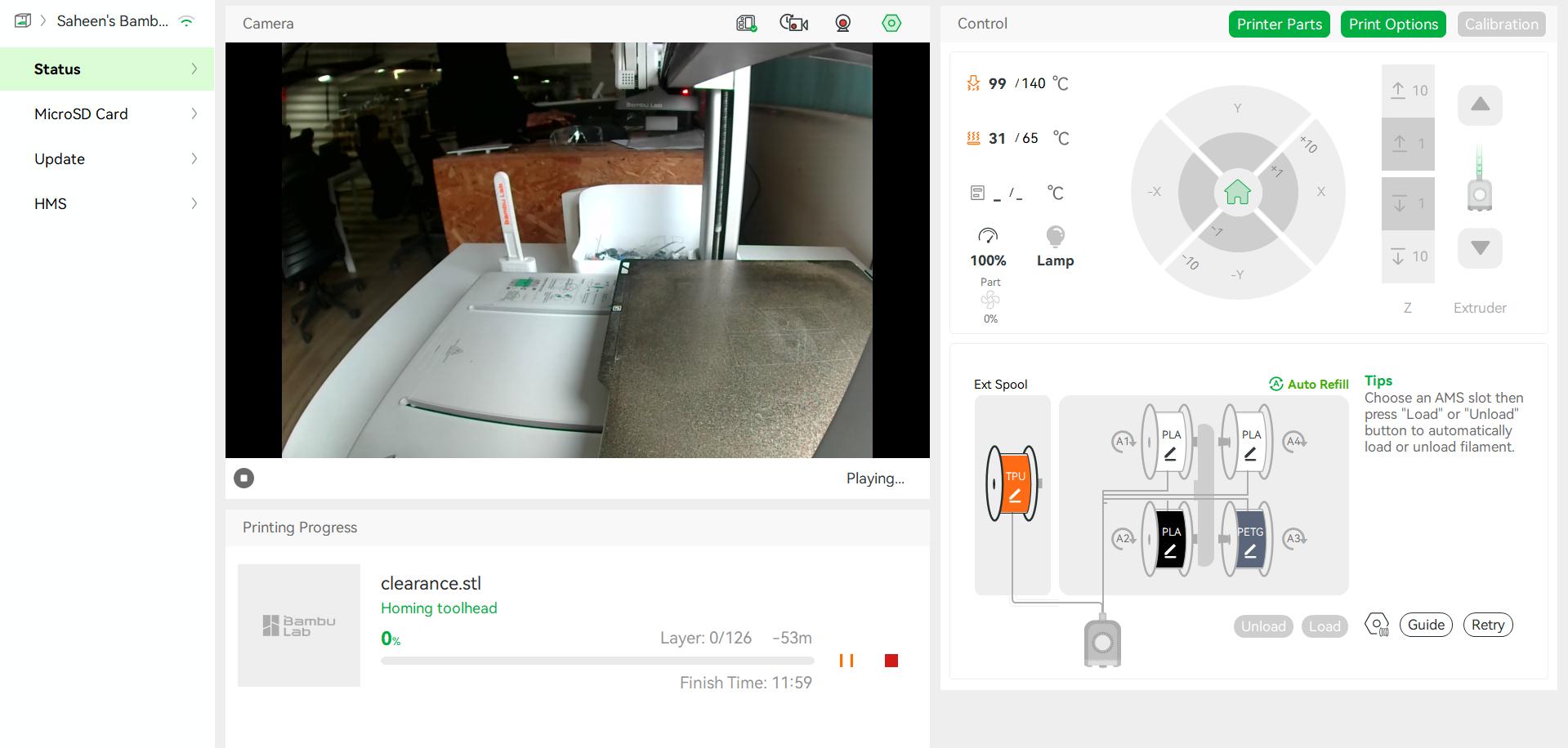
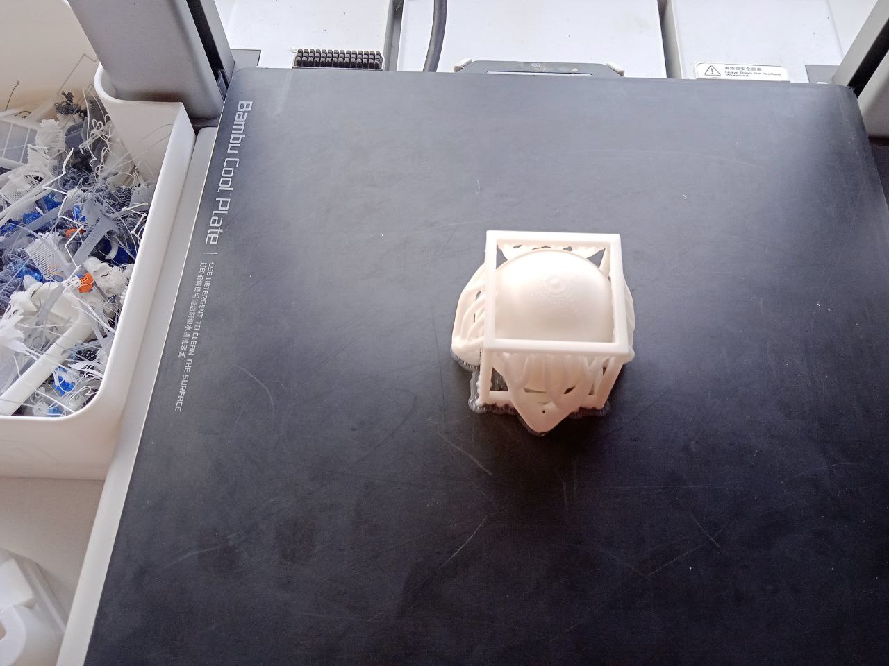
Printing process is shown below.
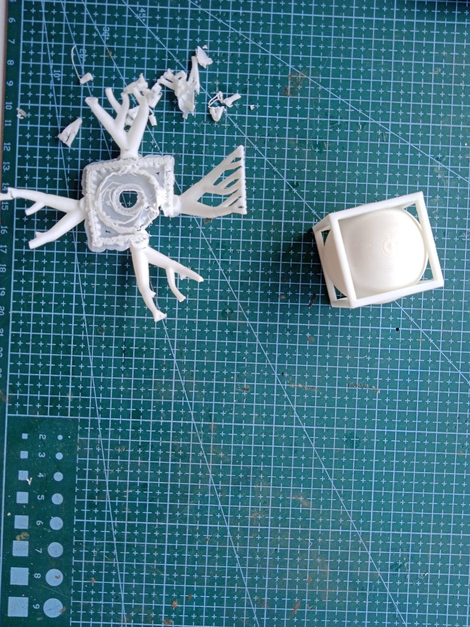
Now we need to remove the support
.jpg)
.jpg)
3D Scanning
3D scanning is a technology that captures the shape, size, and details of a physical object or environment to create a digital 3D model. It uses specialized scanners to collect data from multiple angles, which is then processed into an accurate virtual representation.
How it works?
- Data Capture – The scanner projects light (lasers, structured light, or infrared) onto the object while sensors record how the light interacts with the surface.
- Depth Calculation – The scanner measures distortions in the projected light and calculates 3D coordinates for each point on the object.
- Point Cloud Generation – The collected points form a "point cloud," a raw representation of the object's shape.
- Model processing – Software converts the point cloud into a 3D mesh, which can be refined and exported for applications like 3D printing, virtual reality, or engineering.
Artec 3D scanner
.jpeg)
The Artec Leo is a professional handheld 3D color scanner with automatic onboard processing and a touchscreen display for real-time model visualization.With an upgraded NVIDIA Jetson TX2 processor, it delivers faster processing speeds, enabling high-quality, real-time 3D data capture.
Artec Leo Scanner – Technical Specifications
- Accuracy: Up to 0.1 mm
- Resolution: Up to 0.2 mm
- Accuracy Over Distance: Up to 0.1 mm + 0.3 mm/m
- Algorithms: HD mode, hybrid geometry/texture tracking, auto background removal
- Field of View: 244×142 mm (close), 838×488 mm (far), 0.35–1.2 m working distance
- Texture: 2.3 MP, 24-bit color, supports photo texture
- Speed: Up to 80 fps, 35 million points/sec
- Light Source: VCSEL (3D), 12-LED white array (2D), Class 1 laser (808 nm)
- Hardware: 5.5" touchscreen, built-in battery, 9 DoF sensor, 512 GB SSD
- Processor: NVIDIA Jetson TX2, 256-core GPU
- Interfaces: Wi-Fi, Ethernet
- Computer Requirements (Processing Only): Windows 8.1/10/11, i7/i9, 32–64 GB RAM, NVIDIA GPU
- Output Formats: OBJ, PLY, STL, WRL, STEP, IGES, CSV, etc.
- Dimensions: 231 × 162 × 230 mm
- Weight: 2.6 kg
Scanning the object
I scanned a drill machine .
.jpg)
- Press and hold the power button to turn on the Artec Leo. Ensure the battery is charged or the scanner is connected to a power source.
- Adjust scan settings such as resolution, texture capture, and sensitivity based on the object. Maintain a working distance for optimal results.
- Point the scanner at the object and press the start scan button. Move smoothly around the object to capture all angles. Monitor the real-time 3D model on the touchscreen to ensure full coverage.
- Rotate and zoom in on the scanned model to identify any gaps. Rescan areas as needed for a complete and accurate capture.
- Transfer the scan to Artec Studio software on a PC for further processing, cleaning, and exporting in different formats.
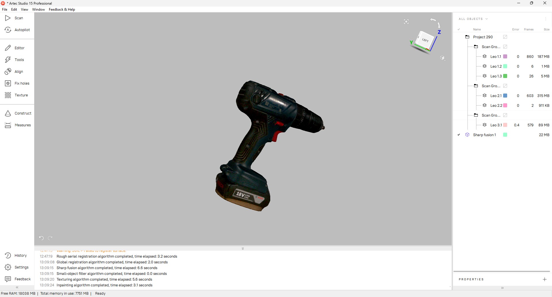
Postprocessing
The scan is transferred to Artec Studio 15 software.
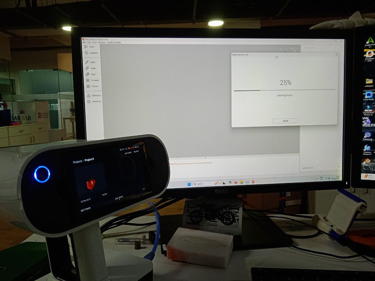
select the scan from file -> import
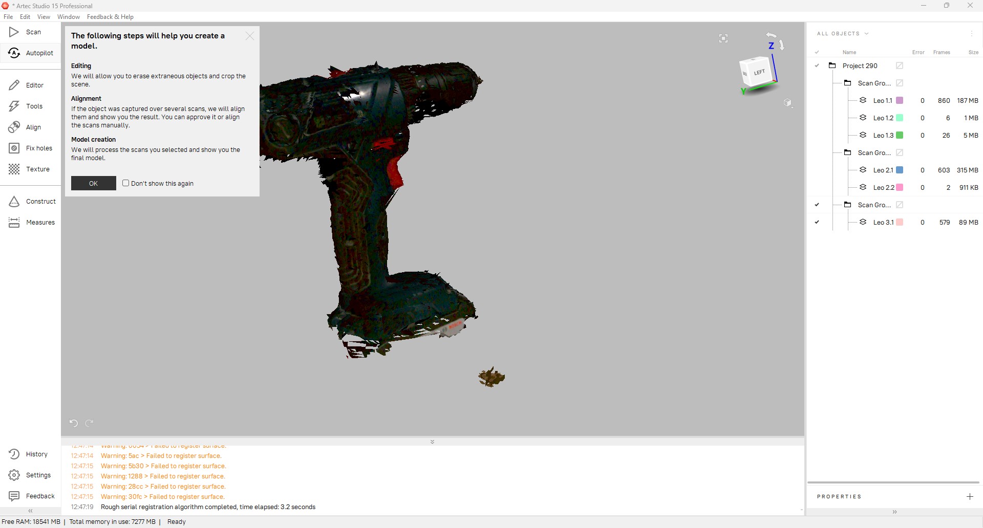
I selected autopilot. Option was shown to edit the scan. Unecessary parts in the background were erased.
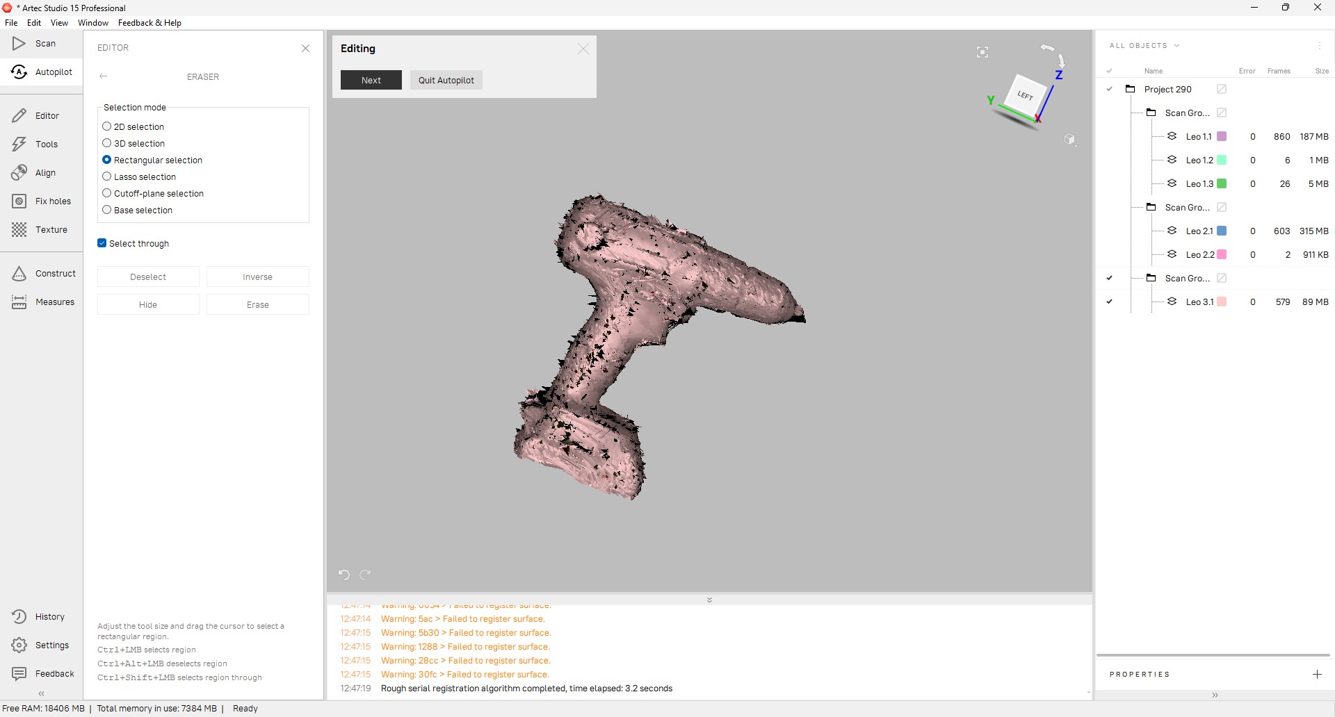
Click next
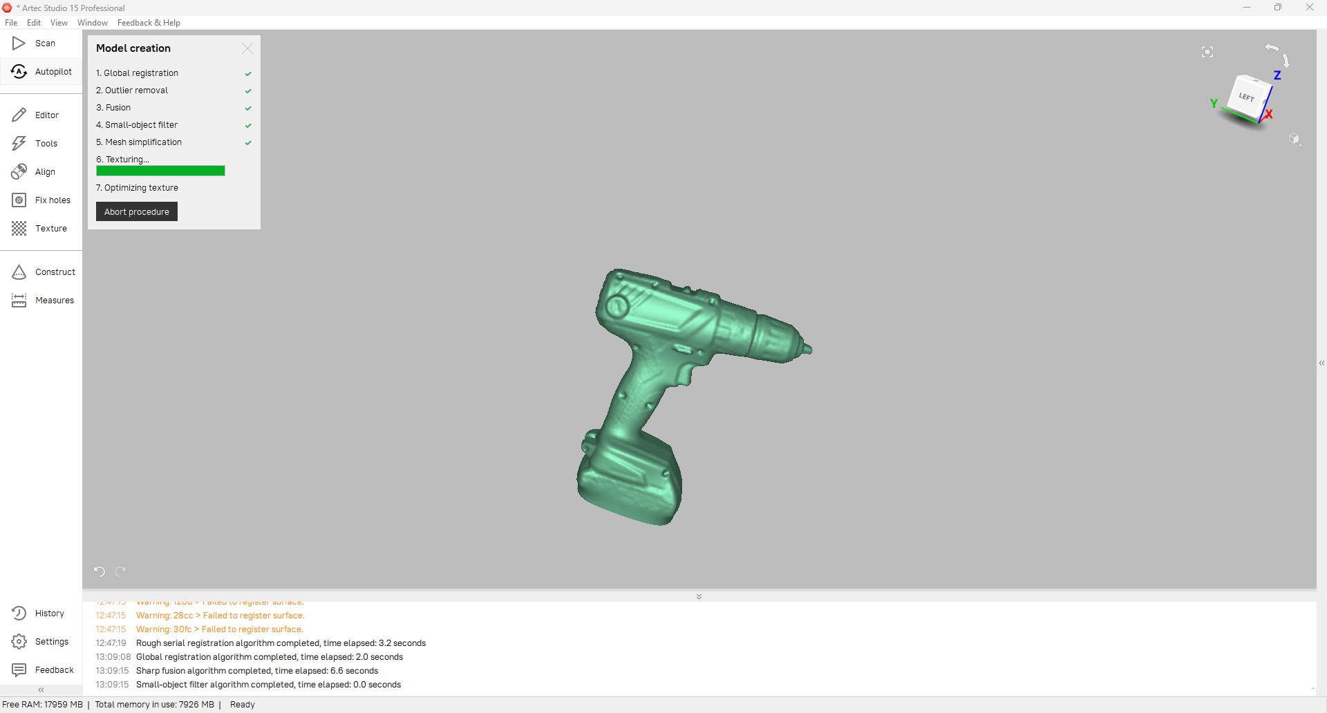
After the process, we get the 3d model of drill machine. The processed scan is then saved in OBJ format.
3dscan by ancyraju77 on Sketchfab