Objectives
Group assignment: demonstrate and compare the toolchains and development workflows for available embedded architectures
Individual assignment: browse through the data sheet for your microcontroller write a program for a microcontroller, and simulate its operation, to interact (with local input &/or output devices) and communicate (with remote wired or wireless connections) extra credit: test it on a development board extra credit: try different languages &/or development environments
Group Assignment
Embedded architecture refers to the hardware and software structure of an embedded system, which is a specialized computing system designed for a specific function within a larger application. Unlike general-purpose computers, embedded systems are optimized for dedicated tasks with constraints on power, size, and real-time performance. In our group assignment different embedded architectures were explored, their toolchains and development workflows were compared.This documentation provides a comparative overview of toolchains and workflows for several embedded development platforms, including the XIAO RP2040, ATtiny1614, ATtiny84, ESP32, STM32F303 Nucleo, and Raspberry Pi. XIAO RP2040 was programmed using Thonny and arduino IDE. Thonny uses microphyton and arduino IDE uses C++ as the programming languages.AT tiny 1614 was programmed in arduino IDE using C++ programming language.As it cannot be programmed directly, we needed a programmer board. It is a FTDI to UPDI converter.To program the ATtiny1614, we use the Arduino IDE with the MegaTinyCore board package. We connect the chip to the computer using a UPDI programmer (like a USB-to-Serial converter with a UPDI adapter). Once everything is connected, we select the correct board and programmer in the Arduino IDE and upload the code using "Upload Using Programmer".To program the ATtiny84, we use the AVR toolchain on Windows, which includes a C compiler and tools like avrdude. We write or use C code, convert it to a hex file, and flash it to the chip using a programmer like the FabTinyISP. The flashing is done using command-line scripts like “hex.bat” and “flash.bat”. Code is written in C/C++ using the Arduino framework inside VS Code with the PlatformIO extension. PlatformIO manages setup, libraries, compiling, and uploads the program to the ESP32 via USB. The correct driver must be installed, and the board and port are configured in the platformio.ini file.The STM32 board support is installed in the Arduino IDE, and C++ code is written using the Arduino API. The code is compiled with the ARM GCC compiler and uploaded using the built-in ST-Link debugger. The correct board and upload method are selected, with STM32CubeProgrammer optionally used for flashing.Raspberry Pi OS is flashed onto a microSD card using Raspberry Pi Imager. Once the card is inserted and the Pi is powered on, the system boots into Linux, where Python or shell scripts can be written using editors like nano. GPIO pins are programmed and code is executed directly from the terminal without the need for a separate compiler or IDE.
Find Group Assignment page here4. Embedded Programming
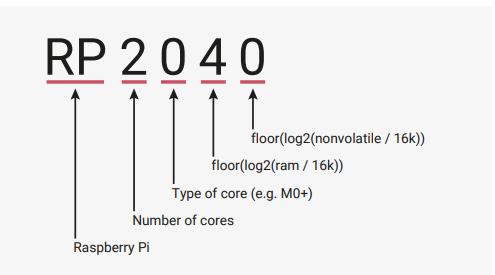
RP 2040
RP2040 is the debut microcontroller from Raspberry Pi
Datasheet of RP 2040
A datasheet is a detailed technical document that describes the features, capabilities, and electrical characteristics of a microcontroller. For the RP2040 microcontroller, the datasheet provides essential information for hardware and software development, including pin configurations, memory layout, peripherals, clock system, power management, and more.
Key Features
- Dual ARM Cortex-M0+
- The RP2040 microcontroller has a clock speed of 133 MHz. This means each of its dual ARM Cortex-M0+ cores operates at 133 MHz.
- 264kB on-chip SRAM in six independent banks
- Support for up to 16MB of off-chip Flash memory via dedicated QSPI bus; meaning the RP2040 itself does not have internal flash memory, but relies on external flash for storing program code and data.
- 30 GPIO pins, 4 of which can be used as analogue inputs
- Communication protocols
- I2C:A widely used protocol for communicating with multiple devices on a single bus, requiring only two data lines (SDA and SCL).
- SPI:Another common protocol for high-speed data transfer between devices, typically utilizing four data lines
- UART: Used for simple serial communication with devices, sending data one byte at a time.
- Built-in Analog-to-Digital Converter (ADC) with 5 channels, offering 12-bit resolution, meaning it can read analog voltage levels with a precision of 4096 possible values between 0 and 3.3 volts on each channel
- Logic levels: High logic is considered near 3.3V, low logic is near 0V. High (1): ≥ 2.0V Low (0): ≤ 0.8V
- Maximum output current per GPIO pin: 12 mA
- Operating voltage: 3.3V
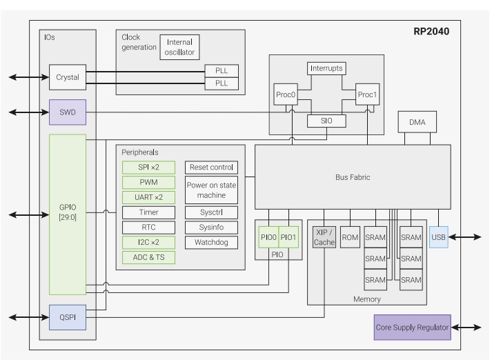
RP2040 has a dual M0+ processor cores, DMA, internal memory and peripheral blocks connected via AHB/APB bus fabric.
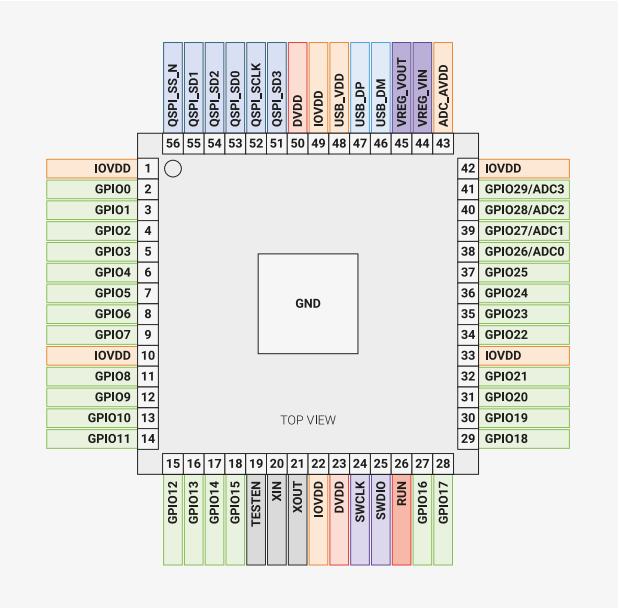
The pinout diagram of RP2040 is shown below.
Wokwi
Wokwi is an online Electronics simulator. You can use it to simulate Arduino, ESP32, STM32, and many other popular boards, parts and sensors.
I worked on Raspberry Pi Pico RP2040 using microphyton. Firt, login to Wokwi
open wokwi -> My projects -> New project ->Raspberry Pi Pico -> Microphyton
 |
.jpeg) |
 |
Now we need to write a program and arrange components for simulation. When we open a new project, we have two panes. Left pane is to write program and right pane is to connect the components and complete the circuit for simulation. To add components click the "+" sign. A list of all components will appear. We can click and drag the components we want. We select the microcontroller before opening the new project. Hover to know the pins of microcontroller. To connect components and chip, simply click on the legs of the components. A wire will appear. Connect it to the microcontroller by clicking the desired pin.
 |
.jpeg) |
Internal pull-up function
An internal pull-up function refers to a feature in many microcontrollers, where a built-in resistor connects an input pin to the supply voltage (VCC). This internal pull-up resistor ensures that the input pin remains at a stable high logic level (HIGH) when no external component is connected, preventing the pin from "floating" and picking up electrical noise that could lead to unreliable or unpredictable behavior. When a device like a push button is connected between the input pin and ground (GND), pressing the button creates a path to ground, pulling the pin LOW and allowing the microcontroller to detect a clear state change. Enabling the internal pull-up in code (e.g., using pinMode(pin, INPUT_PULLUP) in Arduino) eliminates the need for an external resistor, simplifying circuit design and reducing component count.
- I wrote a program to blink an led using push button
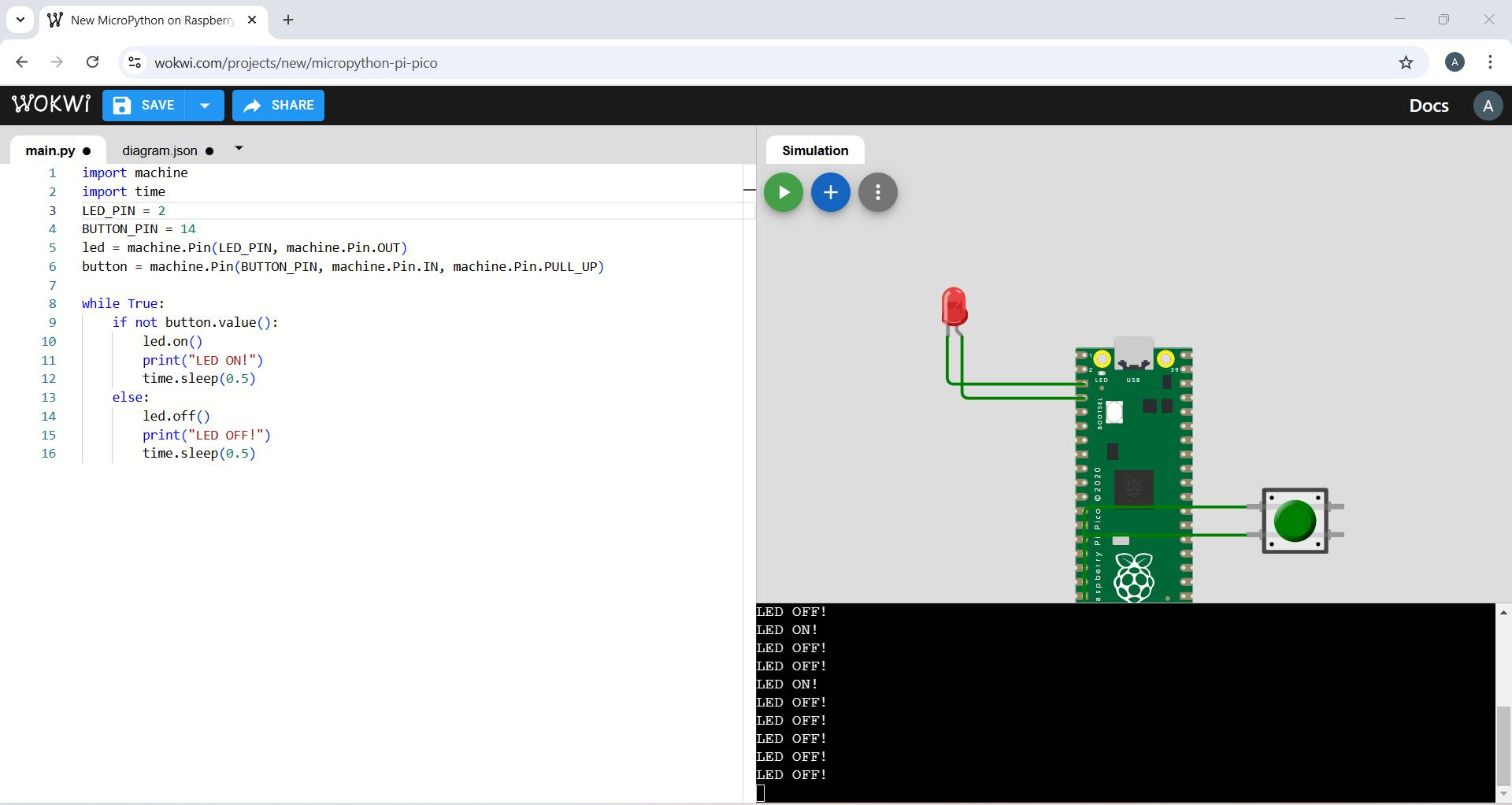
MicroPython is specifically tailored for microcontrollers and embedded devices, enabling developers to write Python code directly on low-power devices. The program code is given below. To comment a line we need to add "#" in the begining
      import machine  # Import the machine module to access hardware-related functions (like GPIO pins)
      import time     # Import the time module for delays and timing functions

      LED_PIN = 2     # Define the GPIO pin number connected to the LED (GPIO 2)
      BUTTON_PIN = 14 # Define the GPIO pin number connected to the push button (GPIO 14)

      # Set up the LED pin as an output pin
      led = machine.Pin(LED_PIN, machine.Pin.OUT)

      # Set up the button pin as an input with an internal pull-up resistor
      button = machine.Pin(BUTTON_PIN, machine.Pin.IN, machine.Pin.PULL_UP)

      # Infinite loop to constantly check the button state and control the LED
      while True:
          if not button.value():  # Check if the button is pressed (value will be False/0 when pressed)
              led.on()            # Turn the LED on
              print("LED ON!")    # Print message to the serial monitor
              time.sleep(0.5)     # Wait for 0.5 seconds to avoid rapid toggling
          else:
              led.off()           # Turn the LED off if the button is not pressed
              print("LED OFF!")   # Print message to the serial monitor
              time.sleep(0.5)     # Wait for 0.5 seconds to avoid rapid toggling
import machine
import time
It allows you to access and utilize functions, classes, and variables defined in external files, known as modules.
LED_PIN = 2
BUTTON_PIN = 14
led = machine.Pin(LED_PIN, machine.Pin.OUT)
button = machine.Pin(BUTTON_PIN, machine.Pin.IN, machine.Pin.PULL_UP)
The LED is connected to GPIO2.The button is connected to GPIO14 with an internal pull-up resistor, meaning it reads high (1) when not pressed and low (0) when pressed.
while True:
if not button.value():
led.on()
print("LED ON!")
time.sleep(0.5)
else:
led.off()
print("LED OFF!")
time.sleep(0.5)
If the button is pressed (button.value() is 0), the LED turns on, and "LED ON!" is printed.If the button is not pressed, the LED turns off, and "LED OFF!" is printed.There's a time.sleep(0.5) delay to prevent rapid toggling.
- I wrote a program for ultrasonic distance sensor LED
I used chatgpt to refer the code.
promt:-How to code for ultrasonic sensor and led varing intensity using rp 2040 and microphyton.
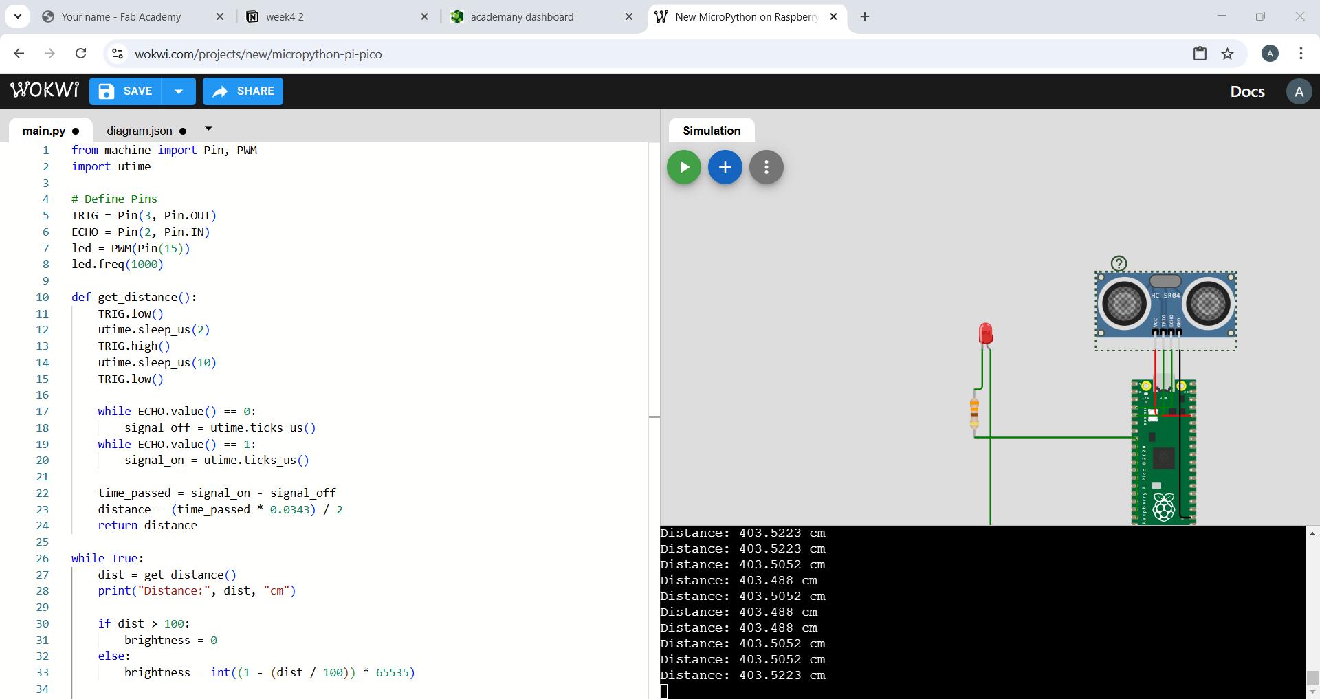
The program code is given below
from machine
import Pin, PWM
import utime
TRIG = Pin(3, Pin.OUT)
This line sets up GPIO pin 3 as an output pin for the trigger of the ultrasonic sensor. This pin sends a pulse to the ultrasonic sensor to trigger a measurement.
ECHO = Pin(2, Pin.IN)
This line sets up GPIO pin 2 as an input pin for the echo signal from the ultrasonic sensor. This pin receives the signal reflected from the object (the echo) after the pulse is sent, and it is used to calculate the distance.
led = PWM(Pin(15))
This line creates a PWM object on GPIO pin 15 to control the brightness of an LED.
led.freq(1000)
This line sets the frequency of the PWM signal to 1000 Hz
def get_distance():
TRIG.low()
This sets the TRIG pin to low (0V). The TRIG pin must be low for at least a short duration before triggering the ultrasonic sensor to send a pulse.
utime.sleep_us(2)
This waits for 2 microseconds means sleep in microseconds to ensure a clean low-to-high transition when the pulse is sent.
TRIG.high()
This sets the TRIG pin to high. This triggers the ultrasonic sensor to send out a pulse of sound.
utime.sleep_us(10)
The TRIG pin needs to be high for at least 10 microseconds to send a pulse. This is the duration of the pulse sent by the ultrasonic sensor.
TRIG.low()
while ECHO.value() == 0:
This loop runs while the ECHO pin is low (0V). When the ultrasonic pulse is sent, the ECHO pin remains low until the pulse is reflected back.The ECHO pin will go high once the pulse is reflected back to the sensor. This first while loop ensures the code waits until the ECHO pin goes high.
signal_off = utime.ticks_us()
When the ECHO pin transitions from low to high, the current time in microseconds is recorded by utime.ticks_us(). This is the moment the signal is sent out. The signal_off variable captures the time at which the pulse was sent.
while ECHO.value() == 1:
This second loop keeps running while the ECHO pin is high. The ECHO pin stays high as long as the pulse is traveling back to the sensor from the object. The code will stop when the ECHO pin goes low again, which indicates the pulse has returned to the sensor.
signal_on = utime.ticks_us()
When the ECHO pin goes low again, the time in microseconds is captured with utime.ticks_us(). This is the moment the reflected pulse has been received by the sensor. The signal_on variable captures the time at which the pulse was received.
time_passed = signal_on - signal_off
distance = (time_passed * 0.0343) / 2
0.0343 is the speed of sound in centimeters per microsecond.Since the time measured includes the round trip (to the object and back), we divide the time by 2 to get the one-way time.
return distance
while True:
dist = get_distance()
print("Distance:", dist, "cm")
if dist > 100:
Here I set the distance as 100 cm
brightness = 0
else:
brightness = int((1 - (dist / 100)) * 65535) >
Dividing dist by 100 scales the distance to a value between 0 and 1 if the distance is between 0 and 100 cm.Subtracting the scaled distance from 1 inverts the mapping.
- If the object is close to the sensor (e.g., 0 cm), dist / 100 would be 0, so 1 - 0 gives 1.
- If the object is farther away (e.g., 100 cm), dist / 100 would be 1, so 1 - 1 gives 0.
- When the object is very close (0 cm), the brightness will be 65535 (maximum brightness).
- When the object is far (100 cm), the brightness will be 0 (LED turned off).
led.duty_u16(brightness)
duty_u16() is a method that sets the PWM duty cycle using a 16-bit value (0–65535).
      from machine import Pin, PWM  # Import Pin and PWM classes to control GPIO and PWM
      import utime                  # Import utime for precise timing functions like microseconds

      # Define trigger and echo pins for the ultrasonic distance sensor
      TRIG = Pin(3, Pin.OUT)  # TRIG pin set as output (sends pulses)
      ECHO = Pin(2, Pin.IN)   # ECHO pin set as input (receives pulses)

      # Set up PWM on pin 15 for controlling LED brightness
      led = PWM(Pin(15))      # PWM object on GPIO 15
      led.freq(1000)          # Set PWM frequency to 1000 Hz

      # Function to get distance from ultrasonic sensor
      def get_distance():
          TRIG.low()              # Ensure TRIG is low before sending pulse
          utime.sleep_us(2)       # Short delay to stabilize
          TRIG.high()             # Send 10 microsecond pulse to TRIG
          utime.sleep_us(10)
          TRIG.low()

          signal_off = utime.ticks_us()  # Start timing (will be updated below)
          signal_on = utime.ticks_us()

          # Wait until ECHO goes high (pulse starts)
          while ECHO.value() == 0:
              signal_off = utime.ticks_us()

          # Wait until ECHO goes low (pulse ends)
          while ECHO.value() == 1:
              signal_on = utime.ticks_us()

          # Calculate the duration of the pulse
          time_passed = signal_on - signal_off

          # Convert time to distance in cm (speed of sound = 343 m/s)
          distance = (time_passed * 0.0343) / 2
          return distance  # Return the measured distance

      # Main loop
      while True:
          dist = get_distance()  # Measure distance
          print("Distance:", dist, "cm")  # Print distance to the console

          if dist > 100:
              brightness = 0  # If object is far, turn LED off
          else:
              # Scale distance to PWM range (closer = brighter)
              brightness = int((1 - (dist / 100)) * 65535)

          led.duty_u16(brightness)  # Set LED brightness (0–65535)
          utime.sleep(0.1)  # Small delay before next reading
- I tried to blink LED using Ardino UNO in wokwi
I used chatgpt to refer the code.
promt:-how to write a code in wokwi adrino uno to blink led using pushbutton
Arduino language, which is essentially a simplified version of C/C++ tailored for microcontroller programming is used here. To coment in arduino uses "//".Everything after // on that line is ignored by the compiler
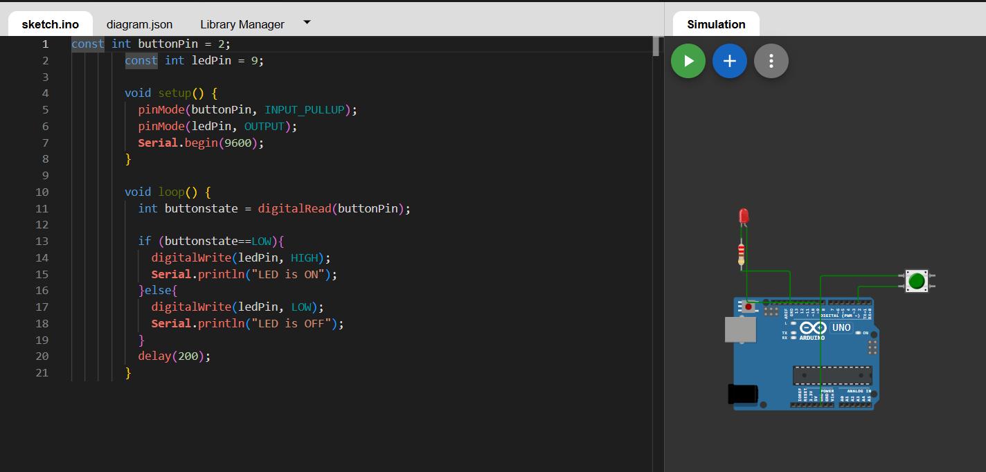
        const int buttonPin = 2;  // Set the GPIO pin number for the button (digital pin 2)
const int ledPin = 9;     // Set the GPIO pin number for the LED (digital pin 9)

void setup() {
  pinMode(buttonPin, INPUT_PULLUP);  // Set button pin as input with internal pull-up resistor
  pinMode(ledPin, OUTPUT);           // Set LED pin as an output
  Serial.begin(9600);                // Start serial communication at 9600 baud rate
}

void loop() {
  int buttonstate = digitalRead(buttonPin);  // Read the current state of the button

  if (buttonstate == LOW) {        // If button is pressed (pin goes LOW)
    digitalWrite(ledPin, HIGH);    // Turn the LED on
    Serial.println("LED is ON");   // Print message to Serial Monitor
  } else {
    digitalWrite(ledPin, LOW);     // Turn the LED off
    Serial.println("LED is OFF");  // Print message to Serial Monitor
  }

  delay(200);  // Wait for 200 milliseconds to debounce and slow down serial prints
}

        }
Code is explained below
const int buttonPin = 2;
const int ledPin = 13;
Defines constant integer for button and LED connected to pin 2 and pin 13 respectively
void setup() {
            pinMode(buttonPin, INPUT_PULLUP);
            pinMode(ledPin, OUTPUT);
            Serial.begin(9600);
          }
setup() function runs once the ardino is powered on/ reset. Button pin defines pin 2 as input. INPUT_PULLUP enables internal pull up resistor,which keeps the pin value high when the button is not pressed. ledPin defines pin 13 as output. In Serial.begin(9600) serial communication begins at 9600 bits per second.
 void loop() {
            int buttonstate = digitalRead(buttonPin);
In void loop, the function runs continuosly.Digital read reads the state of button pin
- If not pressed -> buttonstate=HIGH
- If pressed -> buttonstate=LOW
if (buttonstate==LOW){
              digitalWrite(ledPin, HIGH);
              Serial.println("LED is ON");
If the buttonstate is low, the LED turns ON and serial monitor prints "LED is ON"
else{
                digitalWrite(ledPin, LOW);
                Serial.println("LED is OFF");
Otherwise the LED turns OFF and serial monitor prints "LED is OFF"
delay(200)
Pauses execution for 200 milliseconds. Prevents rapid toggling and reduces flickering.
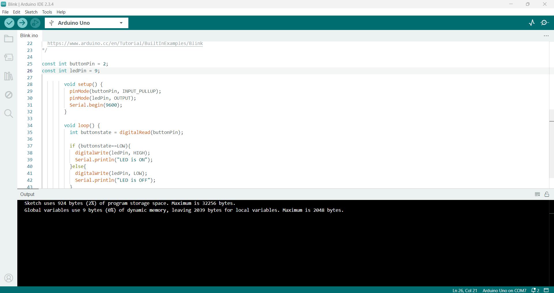
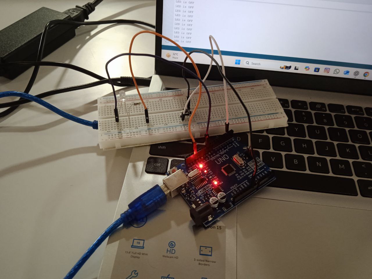
- I tested the code in Arduino UNO
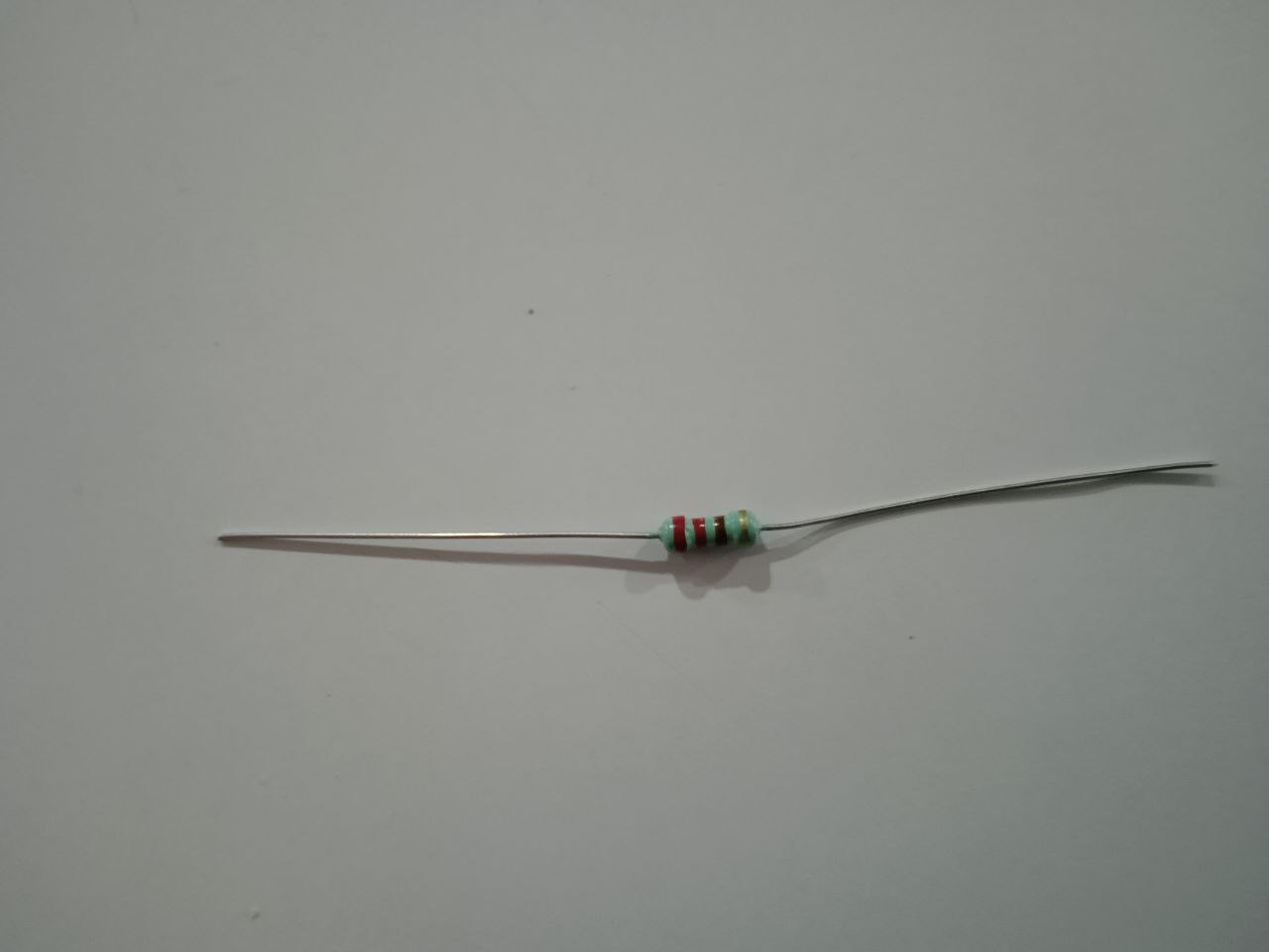
Hardware setup
The resistor is selected using resistor colourcode
LEDs do not have internal resistance to limit current, so they can draw too much current and burn out if connected directly to a voltage source.
Using Ohm's law
𝑅 = V/I
Arduino outputs 5V. A typical LED forward voltage drop is about 2V. Desired current is ~15-20mA (0.02A).150Ω is a minimum safe value, 220Ω is commonly used to ensure safety and longevity while keeping the LED bright enough.
I changed the LED pin to pin 9. Change is made in the code. circuit is connected and code is uploaded using arduino IDE
Conclusion
This week I learned about embedded programming. I learned about various embedded architectures, their toolchains and development workflows. Went through the datasheet of rp2040. Simulated programs in wokwi. Wrote programs for Raspberry Pi Pico and adruino UNO.Tested the program on AdruinoUNO.
Useful links
WokwiArduino
RP2040 Datasheet
wokwi files
Blink leddistance sensor led
Adruino blink led
Design files
DesignfilesHeroshot