Objectives
Group assignment: Do your lab's safety training characterize your lasercutter's focus, power, speed, rate,kerf, joint clearance and types
Individual assignment: Cut something on the vinylcutter design, lasercut, and document a parametric construction kit, accounting for the lasercutter kerf, which can be assembled in multiple ways.
Group Assignment
Test pieces are made from cardboard, wood and acrylic. Kerf values were calculated. From the obtained kerf values, jigs were made to conduct fit test.Values are noted.
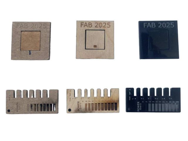
- Cardboard
- Kerf = 0.23
- Wood
- Kerf = 0.245
- Acrylic
- Kerf = 0.125
Laser cutting
Vinyl cutting
Find the group assignment page in the below link
Group Assignment Page3.Computer controlled cutting
Logo cutting using Vinyl cutter
A vinyl cutter is a machine that uses a small, sharp blade to cut designs from sheets of vinyl or similar thin materials. It follows vector paths created in design software to precisely cut shapes, letters, and intricate patterns. After cutting, the excess vinyl is removed in a process called weeding, leaving only the desired design. A layer of application tape is then applied to transfer the design onto a surface while keeping it intact. Vinyl cutters are widely used for making decals, stickers, signs, and custom apparel designs.
Roland GX-24 Vinyl cutter machine
In lab I used Roland GX-24 Vinyl cutter machine.
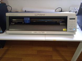
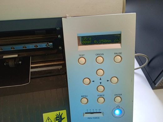
To run the vinyl cutter machine press the blue button on the control panel.Vinyl roll is fed into the vinyl cutter.Feed the vinyl under the pinch rollers and on top of the roller bar and then release the rollers to hold the vinyl in place. We have to choose whether it is a piece or a roll.If piece is selected the size is measured and for rolls,its width is measured. I selected roll. Adjust the origin, force and speed. Run a test cut.
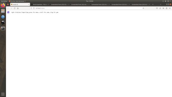
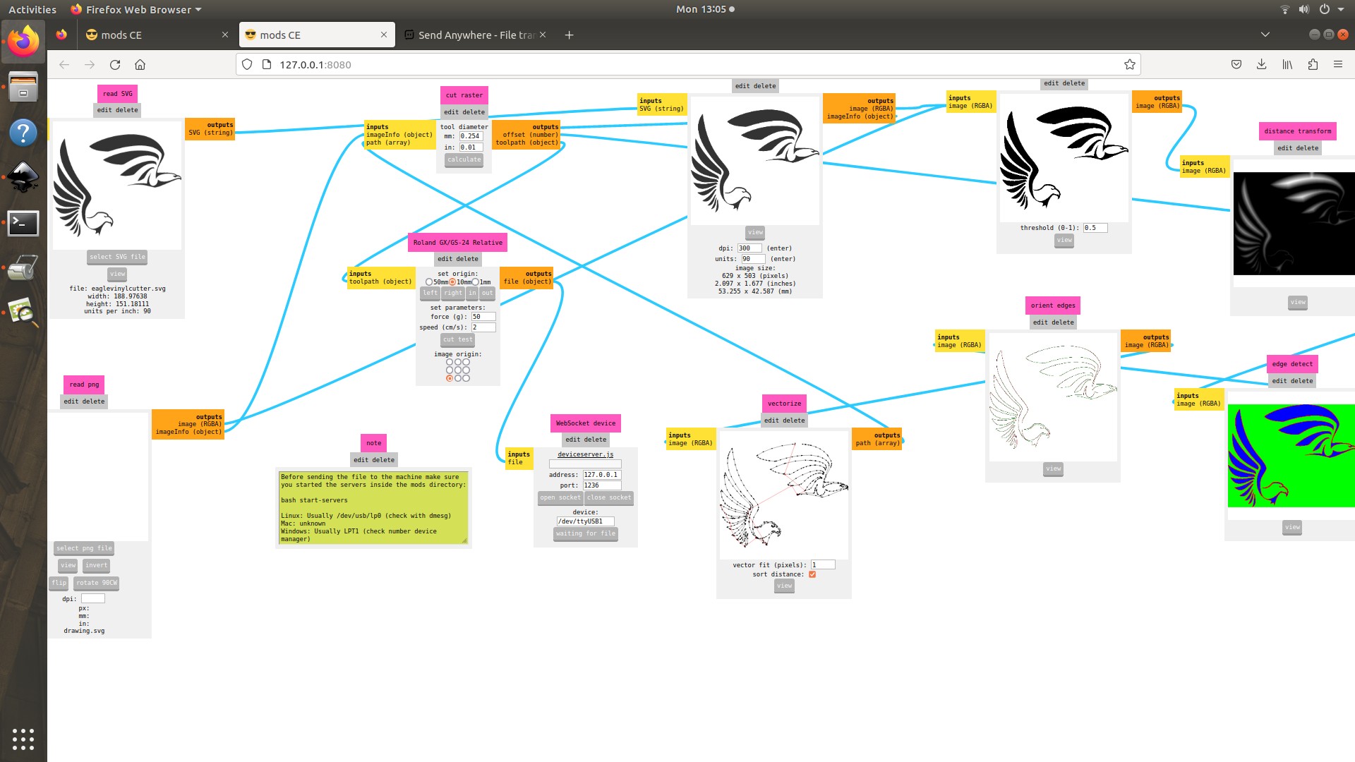
To run the program open mods-master.Fab Mods is an open-source modular digital manufacturing CAM software developed by MIT's Centre for Bits and Atoms to control any machine from a computer. Gave command- bash start servers
mods CE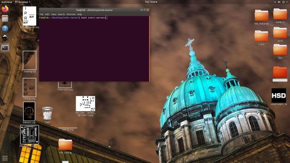
A screen opens. Right click to select program.
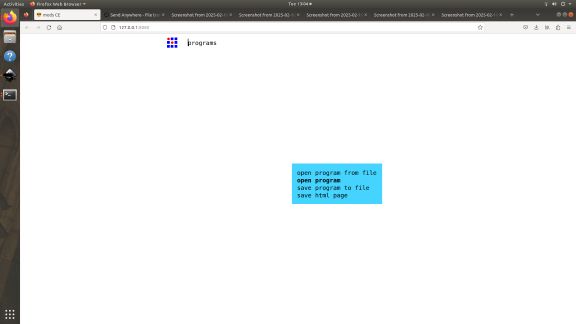
Select program
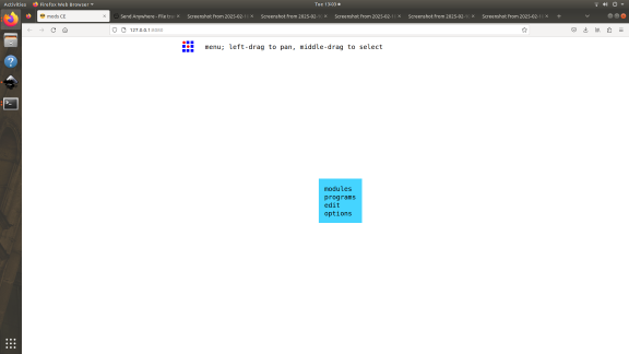
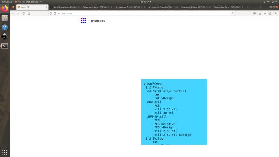
Open program
GX-GS 24 vinyl cutter->cut
I downloaded a raster image, opened it in inkscape. Using trace bitmap option, I changed it to a vector image.The image is then saved and exported for vinyl cutting.
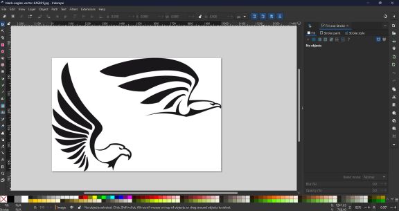 Image source
I inserted svg file. In program,Insert svg file→ calculate→ send file.
 >
>
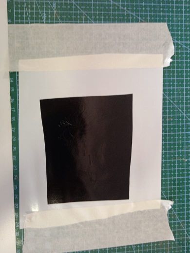
After cutting is completed, we have to weed the image.Weeding is the process of removing material that you don't want in your graphics. The smaller the features in your graphic, the more challenging weeding can become. Use a weeding pick to carefully pull up and remove the portions of vinyl that you don't want to transfer to your target surface.With your image weeded, the next step to take will be to transfer your image from the release liner to the target surface.A transfer tape is used for the purpose. Adher the vinyl to transfer tape. Fix the transfer tape in the target surface and peel away gently.
 |
 |
 |
 |
Parametric construction kit using Laser cutter
Design
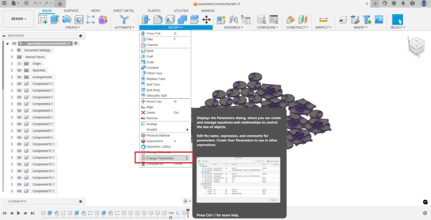
Parameters in Fusion 360 allow users to define and control the dimensions and other properties of a design using named values and equations, making it easier to manage and modify complex designs. They enable parametric modeling, where changes to parameter values automatically update the model, saving time and effort when iterating on designs. To add parameters, modify -> change parameter. the '+' sign let us add parameters to the design. We can define parameters with meaningful names (e.g., "length", "width", "hole_diameter") and assign them numerical values or even formulas that reference other parameters.
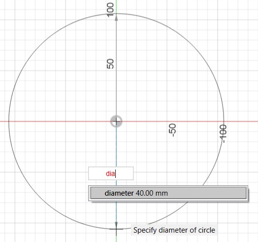
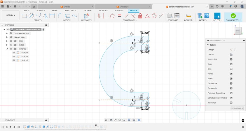
For parametric construction kit , I planned to cut out some pentogons, circles and arches.I chose a regular pentagon with sides 5 cm.For circles, the diameter was selected as 4cm and for arch,the length between two arcs were selected as 3cm. I named the parameters according to my convenience.The shapes were made out of cardboard.
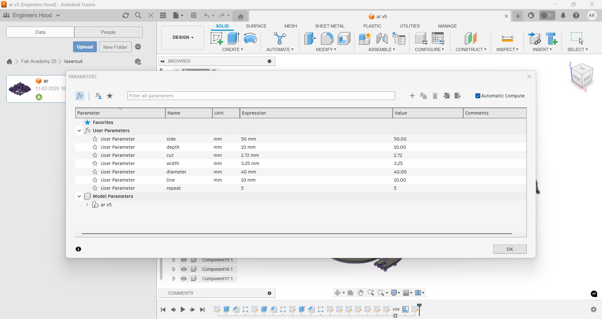
Thickness of the cardboard was calculated. Thickness= 3.25mm, Kerf= 0.23 After fit test the final value was taken as 2.72mm.For fitting two pieces,a portion with 10 mm length and 2.72 mm width is cutout from pentogon circle and arch. The whole procedure is explained in group assignment. Using the final value, sketches are designed accordingly.
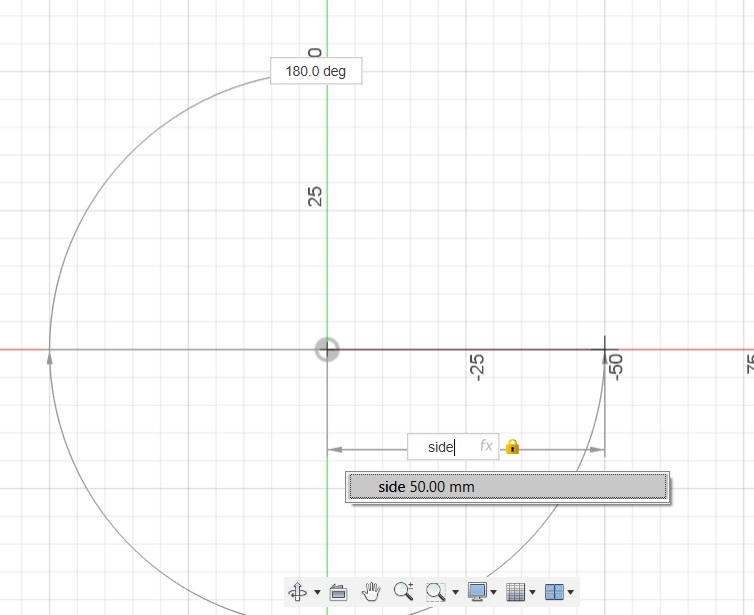
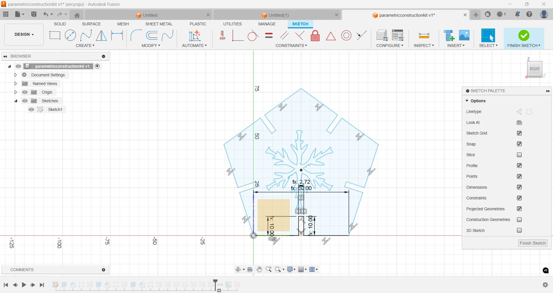
To create a parametric design, I began by creating a new sketch and selecting an appropriate sketch plane. I intended to draw a regular pentagon defined by edge length, so I used the polygon tool and chose the "Edge" option. Instead of entering a fixed value, I typed in a user-defined parameter. In this case, I had already created a parameter named side with a value of 50 mm in the Parameters section. By referencing this parameter, the pentagon becomes dynamic—its size will automatically update if I change the value of side later in the design process.
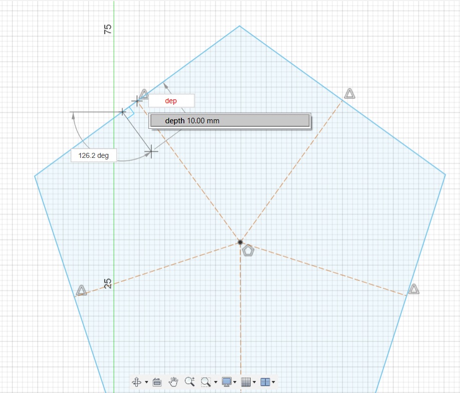
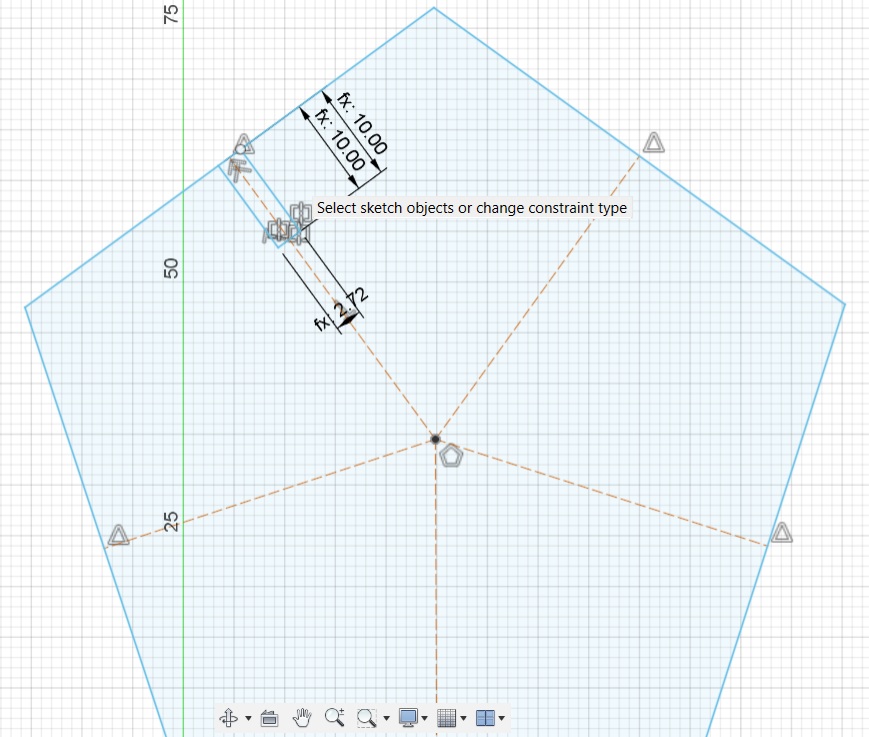
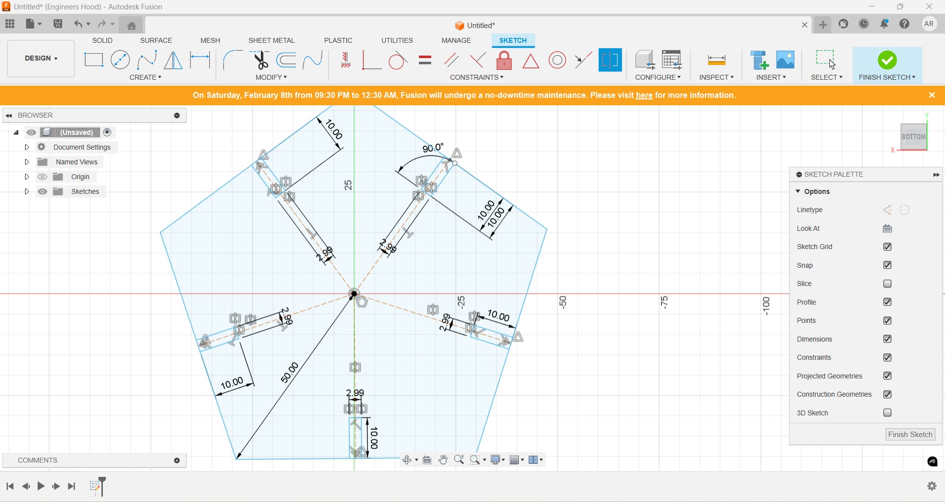
After sketching the pentagon, I added symmetric construction lines to help align features precisely and maintain uniformity. These lines served as references for positioning cut features accurately. Since the design was intended for press-fit assembly, I added cut slots at the midpoints of each side of the pentagon. These slots allow for interlocking pieces without the use of glue or fasteners. To create one cut, I used the line tool and positioned it at the center of one edge. The depth and width of the cut were defined using user parameters—specifically, the depth was set to 10 mm and the width to 2.72 mm. The width value accounted for the actual thickness of the cardboard, adjusted to include kerf compensation for an accurate press-fit.
Once the initial cut was complete, I used the circular pattern tool to replicate it across all five sides of the pentagon, ensuring consistency and symmetry. After applying the pattern, I removed the overlapping edge segments of the pentagon where the cut features intersected, resulting in clean slot joints ready for extrusion and fabrication.
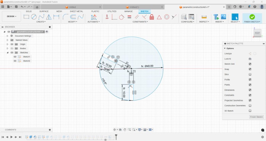
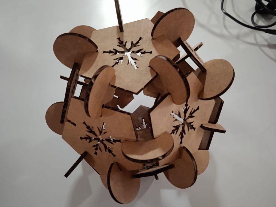
I was planning to create a dodecahedron shape from pentagon. So in circles two cuts for fitting were made at 116.56 deg apart.
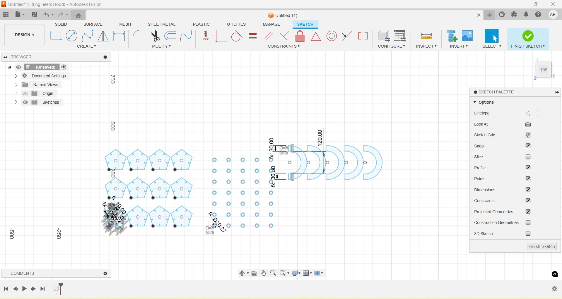
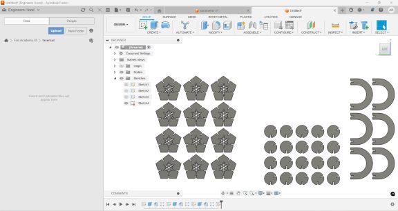
The parametric designs of the three are given below. The image of snow flake was used from previous week and scaled to fit in the pentagon.
Using rectangular pattern multiple images of the same were created.The next step was to extrude the sketches into solid shapes.
Chamfer tool is used to ease the fitting of components. I cut out a snow flake pattern from the pentagon to give an aesthetic feature.
To project , I extruded the sketches into solid shapes
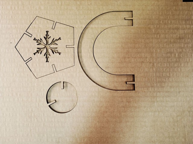
Test cut
I exported the sketches as dxf file for laser cutting. Power is adjusted to 90% and numberof passes is set as 1. Before procedure a test cut was made. The fit was good.
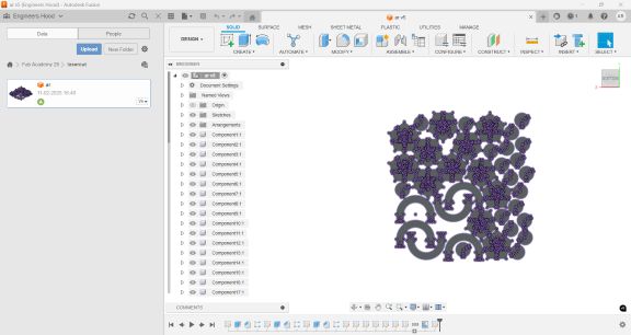
Rearranging
The shapes are then rearranged to minimize space usage and projected. Modify-> arrange. Create-> project.
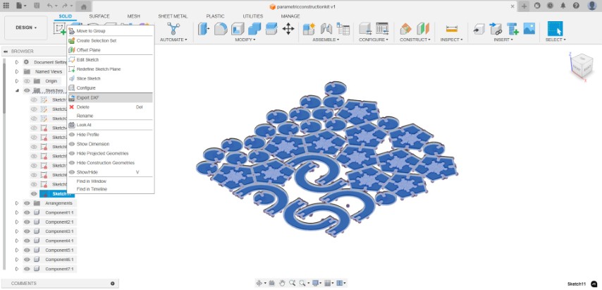
To export the file as dxf, I right clicked the projected sketch and clicked on export as dxf.
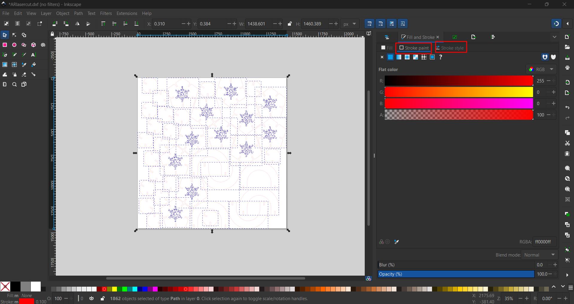
The dxf file is then opened in inkscape. Select the file and add stroke and stroke style. Usually we use red color for cutting and black color for engraving.
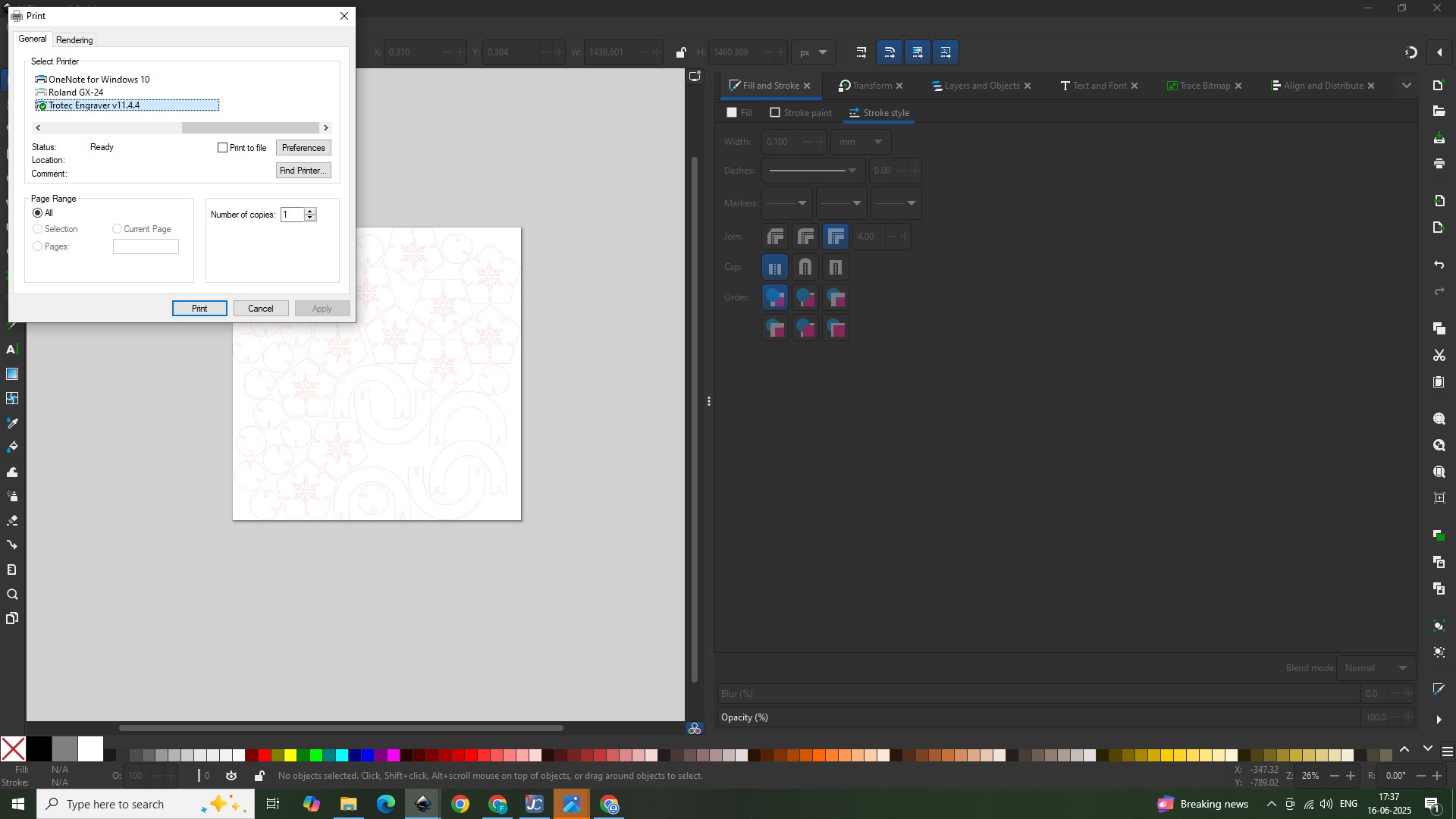
From file select print. A window opens. Select trotec engraver to lasercut the cardboard.
A new window to TROTEC JobControl opens. TROTEC JobControl is a laser software specifically designed for Trotec laser machines. It provides a user-friendly interface for managing and controlling various laser cutting and engraving functions, including job management, positioning aids, and autofocus. From adjust parameters option we can set speed, power, number of passes and other settings.
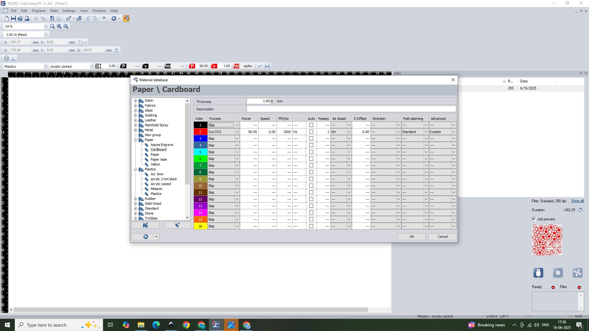
I was using cardboard. I selected the material. power was 90, speed as 2 and number of passes were selected as 1. Then Connect to trotec engraver and click ready.
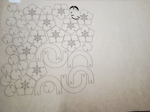
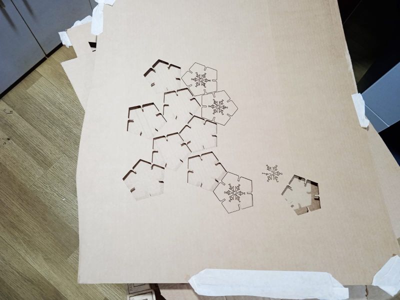
Cut in bulk
Then the entire pattern underwent lasercutting.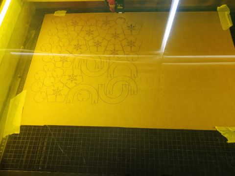
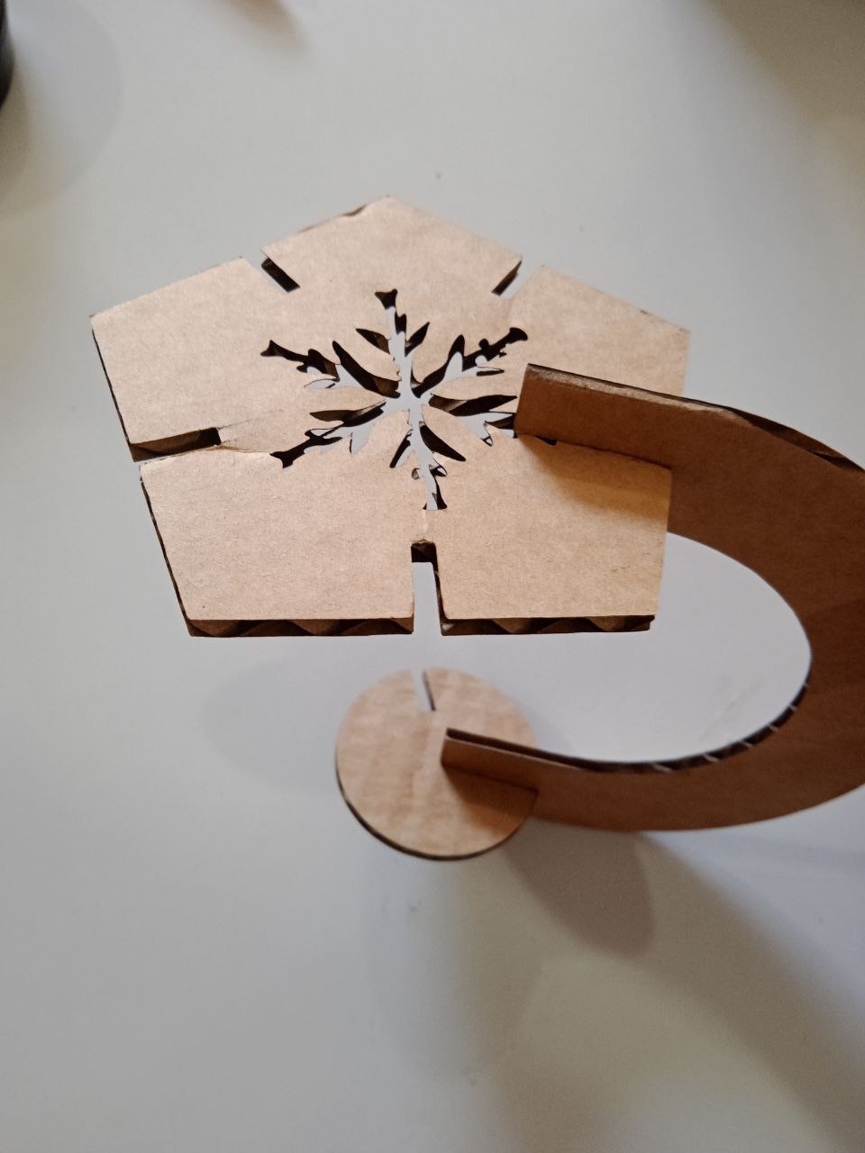
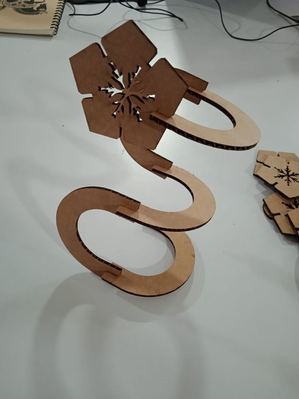
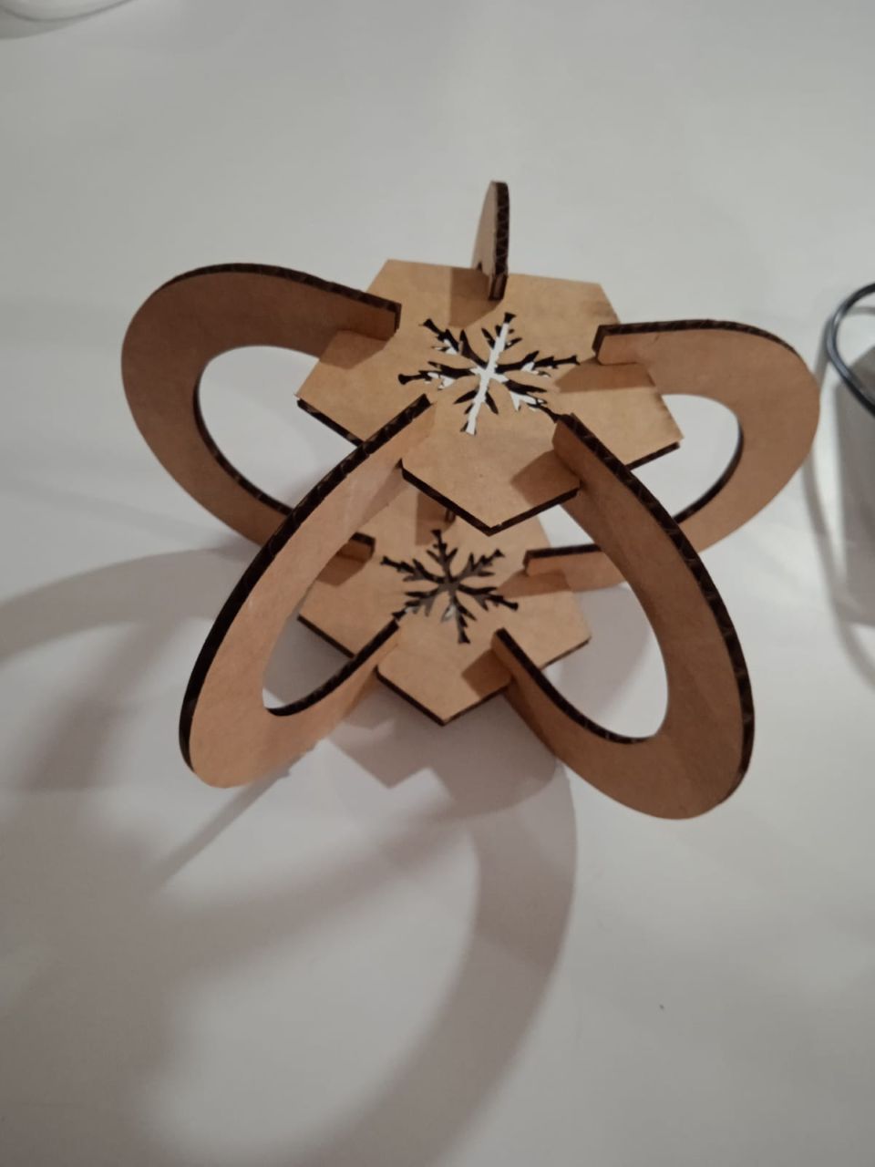
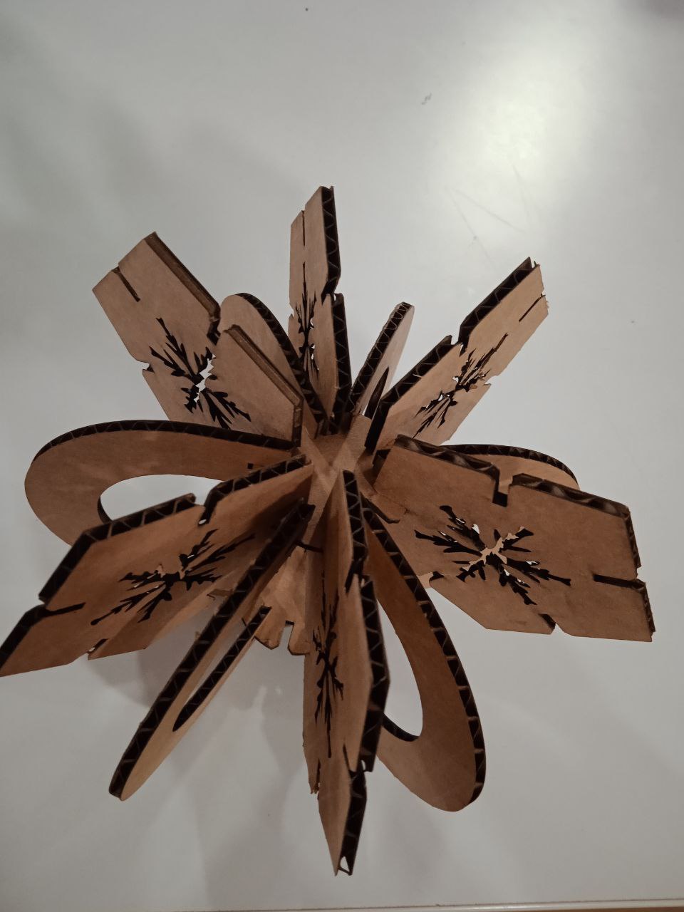
Result
And the result
Challenges faced
Initially the cardboard didn’t stayed at the fixed place, cardboard was bent. Instructor advised to reduce space wastage.
Instead of weeding the logo from vinyl piece, I adhered it on the transfer tape directly.
Conclusion
This week I learned about computer controlled cutting.I used vinyl cutter and created a logo. Using laser cutter, I made a parametric construction kit. Learned about safty measures, to calculate kerf and to construct parametic designs.
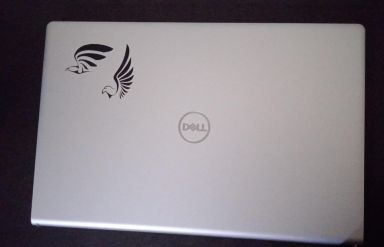
Hero Shot
Files
lasercut design filesvg file
logo