Week09: Input Devices
Group Assignment
Probe an input device’s analog levels and digital signals
This group assignment document was written by Shintaro Ito.
01. Summary
For the group assignment, an experiment was conducted to measure the analog and digital signals of the joystick and sound detection module using an oscilloscope.
For the joystick, although the buttons worked properly, no changes in the X- and Y-axis signals could be confirmed, indicating a problem with the device itself.
On the other hand, for the sound detection module, voltage changes in response to sound were confirmed for both analog and digital signals, and the signal characteristics were compared.
02. Machines Used This Time
- Oscilloscope Information
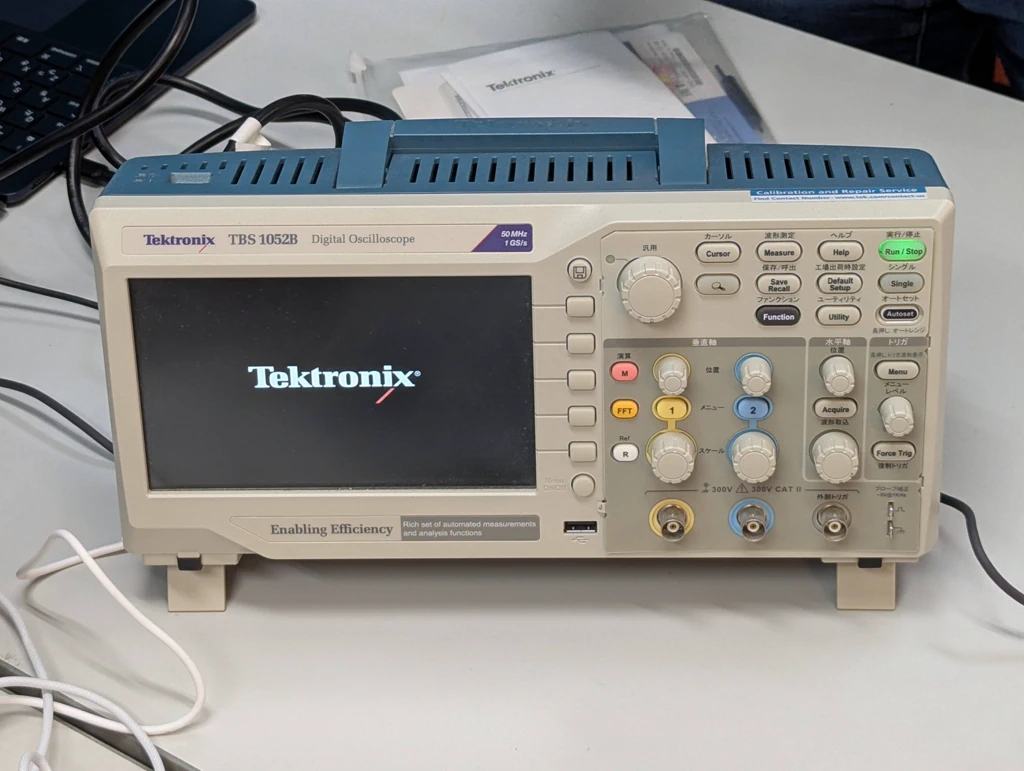
For more information, please click this page.
03. Items Used
- xhao rp2040
- FA25 Kannai Devboard
- Joystick (Datasheet)
- Sound Detector (Datasheet)
04. Measuring Input Using a Joystick
step01: Understanding the Joystick
The joystick has the following three outputs:
- X-axis
- Y-axis
- Button

Also, the joystick pinout is as shown in the image.

step02: Preparing an Electrical Circuit to Operate the Joystick
This time, we created an electrical circuit on a breadboard using the xhao rp2040 as a power source.

For clarity, a diagram of the electronic circuit is also included. A connection for measurement with an oscilloscope was prepared in between.

step03: Creating a Program to Run Electricity and Display the Joystick Output
The code is as follows:
from machine import Pin, ADC
from time import sleep

# Pin settings
JoyStick_X = ADC(Pin(29))  # X-axis signal (corresponding analog pin number)
JoyStick_Y = ADC(Pin(28))  # Y-axis signal (corresponding analog pin number)
Button = Pin(27, Pin.IN, Pin.PULL_UP)  # Button pin (pull-up resistor enabled)

def read_voltage(adc):
    # Convert analog value to voltage
    return adc.read_u16()#  * (3.3 / 1023.0)  # 3.3V reference, 10bit resolution
    # return adc.read_uv() * (3.3 / 1023.0)

while True:
    # Get joystick voltage
    xStatus = "middle"
    yStatus = "middle"
    buttonStatus = "not pressed"

    x_voltage = JoyStick_X.read_u16()
    y_voltage = JoyStick_Y.read_u16()
    # x_voltage = read_voltage(JoyStick_X)
    # y_voltage = read_voltage(JoyStick_Y)

    # Get button state
    button_state = Button.value()

    # Output voltage and button state
    print("X-axis: {:.2f} V, Y-axis: {:.2f} V, Button: {}".format(
        x_voltage, y_voltage, "not pushed" if button_state == 1 else "pushed"))


    if button_state == 0:
        buttonStatus = "pressed"

    if x_voltage <= 600:
        xStatus = "left"

    if x_voltage >= 60000:
        xStatus = "right"

    if y_voltage <= 600:
        yStatus = "up"

    if y_voltage >= 60000:
        yStatus = "down"

    print("X: " + xStatus + ", Y: " + yStatus + "  button status: " + buttonStatus)

    sleep(0.2)  # 200ms delay
step04: Actually Run the Program and Measure Using an Oscilloscope
The switch responds, but the X and Y axes could not be measured.
Switch
It can be seen from the voltage change on the oscilloscope that the voltage decreases when ON and increases when OFF.
plaese delete 'docs/'
X and Y Axes
It can be seen that the voltage on the oscilloscope does not change even when the joystick is moved.
plaese delete 'docs/'
step05: Troubleshooting the Issue of the X and Y Axes Not Working
From the following verification, we concluded that there was a problem with the joystick itself.
- Cable: Since the joystick switch works without any problems, we replaced each cable and confirmed that there were no operational issues.
- Program: We found a video of the code we referenced in operation. We confirmed that there were no problems even when comparing the contents.
- Power: As a result of measurement with an oscilloscope, no voltage change due to the input of the X and Y axes could be confirmed.
05. Measuring Input Using a Sound Detection Module
step01: Understanding the Sound Detection Module
The Sound Detection Module has the following two outputs:
- Analog Output
- Digital Output
The other components are as shown in the image below.

step02: Creating an Electrical Circuit to Operate the Sound Detection Module
This time, we created an electrical circuit on a breadboard using the xhao rp2040 as a power source.

For clarity, a diagram of the electronic circuit is also included. A connection for measurement with an oscilloscope was prepared in between.

step03: Creating a Program to Run Electricity and Display the Sound Detection Module Output
The code is as follows:
//Lesson 44 Microphone sound sensor module
//Sound detection sensor part 2
//https://omoroya.com/

// const int led = 13;       // For LED lighting confirmation
const int digitalPin = 29; // Sensor D0 output connection destination
const int analogPin = 28;  // Sensor A0 output connection destination

void setup()
{
  // pinMode(led, OUTPUT);         //Specify pin 13 as output
  pinMode(digitalPin, INPUT);   //Specify pin 7 as input
  Serial.begin(9600);           //Specify the serial communication data transfer rate at 9600bps
}

void loop()
{
  int d_val;   // digital variable
  float a_val; // analog variable

  // D0 output control
  // d_val = digitalRead(digitalPin);
  // if(d_val == HIGH){         // D0 output is HIGH
  //   digitalWrite(led, HIGH); // Pin 13 HIGH output (L-chika ON)
  // }
  // else if(d_val == LOW){     // D0 output is LOW
  //   digitalWrite(led, LOW);  // Pin 13 LOW output (L-chika OFF)
  // }

  // A0 output control Lesson 43 converts voltage (to make sensitivity adjustment easier)
  // If the power supply to the module is 5V, the threshold should be approximately 2.5V.
  // a_val = analogRead(analogPin);                      //Read A0 data
  a_val = (float)analogRead(analogPin) / 1024.0f * 3.3f; // Read A0 data and convert to voltage
  Serial.println(a_val);                                 // Output to serial monitor

  delay(100);
}
step04: Actually Run the Program and Measure Using an Oscilloscope
Analog Signal
It can be seen that the voltage on the oscilloscope is changing due to the sound.
plaese delete 'docs/'
Digital Signal
You can see that the voltage of the oscilloscope is changing due to the sound. You can see that it is more rectangular compared to the analog signal.
plaese delete 'docs/'
Comparison of Analog and Digital Signals
I tried comparing analog and digital signals using the function of an oscilloscope. Light blue is the analog signal, and yellow is the digital signal.
Compared to the analog signal, which only generates a voltage amplitude of about 20mV, the digital signal shows that a voltage of about 3.3V is flowing.
