Week 12: Mechanical & Machine Design
Table of Contents
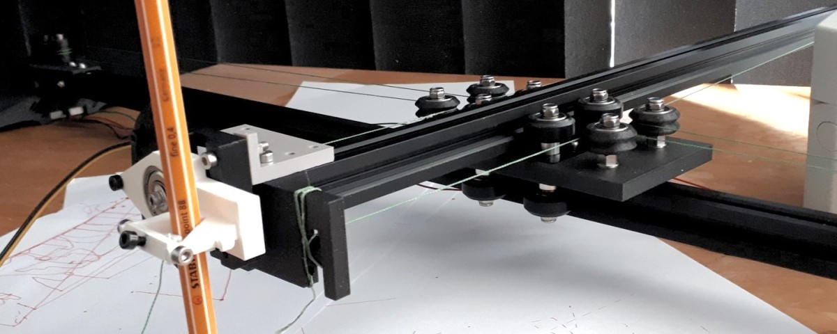
This week, we built a two-axis drawing machine in a small group. Inspired by the projects UrumbotXY 2.0 and AxiDraw, we designed it to work with an H-bot motion system driven by a capstan drive. The whole documentation can be found on the group page while this page contains the work I have contributed to the project, which included parts of the CAD as well as the automation part. I worked together with Niclas and Matthias.
This Week’s Tasks
Mechanical Design (part 1 of 2)
- Group assignment:
- Design a machine that includes mechanism + actuation + automation + application.
- Build the mechanical parts and operate it manually.
- Document the group project.
- Individual assignment:
- Document your individual contribution.
Machine Design (part 2 of 2)
- Group assignment:
- Actuate and automate your machine
- Document the group project
- Individual assignment:
- Document your individual contribution
Group Page
This assignment was done in a group. The whole documentation can be reached via the above link. On this site, I documented my own contribution to the project. Some parts were copied from the main documentation, some where written originally.
The following video was recorded to present the project in class. At the time of recording, the machine could not draw circles.
This was fixed afterwards. Details can be read below.
Design
The sketches for the initial idea of the machine we made as a group.

When we did the CAD, I searched for and downloaded standard components we used (extrusions, plates, wheels, …) from OpenBuilds. Afterwards, I modeled and assembled first versions of the mobile carriage and the mounting plate for the motor. Niclas and Matthias put much work into re-designing it later on to make it more stiff. They went through multiple iterations of designing, digital assembly and printing to make sure everything fitted well together.


After the mechanism was assembled, we operated it manually.
Actuation & Automation
We now had a mechanism and motors driving it. The next step was to tell the motors what to do in order to draw a picture. This involved setting up a driver for the motor (a circuit that translates step signals into current flowing through the coils in the motor to make it move), a software that sends step signals to the drivers based on given machine code (referred to as firmware), a GUI that interfaces the user with the firmware, enable them to send machine code to the firmware and to come up with a workflow to generate G-code from an .svg file.
Setting up the Controller
To automate the machine, we used a RAMPS kit. It is a set consisting of an Arduino board supposed to run the firmware, Pololu-style stepper motor drivers, as well as a shield for the Arduino board to connect power supply and drivers. The drivers we used were of the type DRV8428. For assembling everything, we followed the steps at the RepRap wiki.

The power supply we used had open contacts with above 200V.

We wanted to avoid touching them so a cover was designed using FreeCAD. Note the rounds where two straight pieces meet. This is to avoid the cover breaking at the corner.

Every driver had a slot to put it at. Under the driver there were jumpers. They could be set to configure micro-stepping. We set all jumpers to enable the setting with the smallest-possible steps. The driver carrier had an adjustable resistor which was used to adjust the maximum current the driver would provide to the motor.

Afterwards, we needed to connect the motors to the board. Our stepper motors had four wires attached. The question to answer was how to arrange them so that the motor works correctly? Each motor contained two coils. The two ends of each coil were led out of the motor. There were two coils so there were four cables in total. To identify a coil pair, we measured the current between each pair of wires and turned the motor. This induced a current in both coils which could then be measured. The current induced was alternating current since the motor was turned manually. We measured with the direct current setting. This did not matter that much, because we only were interested if there is current flowing or not. We noticed a significant change in the measured current when the motor was turned. The pairs identified were blue, red and black, green.

1A 1B 2A 2B is the original order of the cables:
- If you change the order of one of the cable pairs (
1A 1B 2B 2A), the direction of the motor changes. - If you change the order of both of the pairs (
1B 1A 1B 1A), this is invariant to the direction of the motor direction. - If you change both cable directions and you switch the pairs (
2B 2A 1B 1A), this changes the direction of the motor.
It is important to note that one always needs to turn off the power when messing with the connections of the ramps board. Plugging the motor cables while there is still a power supply connected could destroy the circuitry in the RAMPS kit. For the following video the hello world sketch provided at the RAMPS wiki page was flashed.
Regarding orientation of the connector: the side of the connector that is facing the driver is labelled with “d”.
Setting up Firmware & GUI
As a firmware to flash onto the Arduino we used Marlin. We followed the installation instructions and used PlatformIO. There were no difficulties with that. First, we flashed it without further modifications. Later, we adjusted the file Configuration.h to configure the firmware. To send machine code from a desktop PC/laptop to the firmware via USB, we used Printrun with Pronterface as a GUI.

Note that the baud rate needs to be the same in the configuration file of the firmware as well as in Printrun.
1#define BAUDRATE 250000
After adjusting this, one needed to connect to the Arduino board by hitting the corresponding button.

End Stops
We then connected the end stops to the ramps shield as described in the RAMPS wiki. With Marlin, the G-code M119 yielded the state of the end stops which was helpful for checking if their activation is recognized.

Servo Motors
To set up servo motors with RAMPS and Marlin one connects the servo motor as depcted in the RAMPS wiki. In Marlin’s configuration, the following line needs to be uncommented.
1#define NUM_SERVOS 1 // Note: Servo index starts with 0 for M280-M282 commands
Then, the servo could be controlled using the G-codes M280, M281, and M282.

Configuring Firmware: Motion System & Steps/mm
Our motion system was not as simple as “one motor turns, the other not -> only one axis moves”, because instead of a cartesian motion system we had an H-bot. When both motors were turning in the opposite direction, the vertical axis was moving. When both motors were turning in the same direction, the horizontal axis was moving. When only one motor was moving and the other one not, both the vertical and the horizontal axis were moving to the same extent. For the mechanism to be automated correctly, we needed to configure the firmware accordingly. The configuration for the motor behavior was the same as with the CoreXY motion system, so we configured the firmware to drive the motors according to CoreXY’s rules.
1// Enable one of the options below for CoreXY, CoreXZ, or CoreYZ kinematics,
2// either in the usual order or reversed
3#define COREXY
4//#define CoreXZ
5//#define COREYZ
6//#define COREYX
7//#define COREZX
8//#define COREZY
We put a tape onto our capstan thread and marked the extrusion with white tape where the right end of the tape attached to the thread was. We then moved 10mm in one axis, marked the extrusion again and measured the distance.

desired distance traveled/actual distance traveled = desired steps/actual steps. The unknown variable was desired steps. Resolving the equation yielded desired steps = desired distance traveled/real distance traveled * actual steps. The actual steps were taken from the original configuration which were 80. Calculating the new steps/mm yielded a value of 102 steps/mm. It is a good idea to repeat this procedure iteratively several times to get a more precise value for the steps/mm. However, already at the second iteration, we got a new value of 102.4 steps/mm, so we did not change the steps/mm any further. For more calculations regarding stepper motors in CNC machines, this calculator might come in handy.
1/**
2 * Default Axis Steps Per Unit (linear=steps/mm, rotational=steps/deg)
3 * Override with M92
4 * X, Y, Z [, I [, J {, K...]]], E0 [, E1[, E2...]]
5 */
6#define DEFAULT_AXIS_STEPS_PER_UNIT { 102, 102, 400, 500 }
In the end, it was possible for our machine to move correctly.
Drawing a Circle
For testing, I generated a tool path to draw a simple circle. Checking the G-code using ncviewer confirmed that the G-code indeed described a circle being drawn.

Unfortunately, the result was not a circle. Also, the origin of the start and the end position of the head was different. This was not as intended.
The problem here was that the capstan drive thread was a little bit too loose and the pen was not stiff enough. We tightened the thread and, due to lack of time for this week, we used hot glue to fixture the pen at the machine’s head.

After that, a circle was drawn. This time, we also fixtured the paper by applying 3m77 spray onto the surface the paper was drawn on. When doing that we learned a trick: after using a spray can, turn it upside down and spray until only air comes out. This way, the nozzle gets cleaned. Otherwise it might get sealed by residual material from inside the can.
Working with G-code
During working with the machine and debugging it, we used G-code to manually control the machine. The following G-codes turned out to be used often:
- G092: set WCS position (useful for homing manually)
- M114: get position
- G054 - G059: handle different WCSs
- G91: relative coordinate mode
- G90: absolute coordinate mode
Reflections
What I Learned
- You can use OpenBuilds for searching for pre-made CAD parts.
- When structuring large FreeCAD projects, we had the convention to have a separate FreeCAD file for every part and for every assembly.
- How to use fasteners in FreeCAD.
- Distance joints are good in FreeCAD if you want to put something onto something else (instead of the fixed joint). The assembly for the Dreieck I should have done with combination of slide and distance joints. Here, I mostly used rotational and distance joints.
- When designing a machine, it is better to first have a crappy cardboard prototype or a blender prototype where everything is in included. Its purpose would be for checking if all dimensions fit.
- How to drive stepper motors. Here, I used the RAMPs kit for doing this. However, it would be very much possible to design and mill the driver PCBs yourself.
- How to set up a RAMPS kit with Pololu-style drivers to drive stepper motors.
What Went Wrong
- Some 3d printed parts were not stiff and needed to be re-designed.
- Towards the end of the project, we had difficulties drawing what we wanted to draw based on the generated G-code. This was fixed by tightening the capstan thread and fixturing the pen in a stiffer way.
- I was not able to generate G-code using Inkscape. However, this seemed to be a problem with my setup. On other systems it worked.
- It took much time to get the capstan-driven machine to work. This led to much effort for documentation after the corresponding week.
What Went Well
- We did not expect the capstan drive to work on the first try. However, it did. We were very happy about that.
What I Would Do Differently
- If I would repeat this assignment, I would use a belt instead a capstan drive. It took much time to debug this type of drive.
Digitial Files
Digital files are provided at the bottom of the group page.
Use of Language Models
During writing this report, I did not use any language models for this assignment.