Week 4: Embedded Programming
Table of Contents
This week was MOSTLY LITERATURE RESEARCH.
If you are INTERESTED IN MY PROGRAMMING WORK during the program, please refer to the networking week or the final project
This week we got introduced to embedded programming. Our tasks were to compare different development workflows for available embedded architectures, read the data sheet of one preferred micro controller unit (MCU), and to briefly demonstrate basic programming skills.
This Week’s Tasks
- Group assignment:
- Demonstrate and compare the toolchains and development workflows for available embedded architectures
- Document your work to the group work page and reflect on your individual page what you learned
- Individual assignment:
- Browse through the data sheet for your microcontroller
- Write a program for a microcontroller, and simulate its operation, to interact (with local input &/or output devices) and communicate (with remote wired or wireless connection)
Introduction to Embedded Programming
This week’s lecture covered aspects of embedded programming. It discussed selecting the appropriate MCU family, such as AVR or ARM, based on application needs. Different programming languages were explored, including C/C++, Rust, and (Micro)Python, each with its own advantages and trade-offs for embedded systems. The session also touched on development tools, debugging methods, and operating systems, highlighting the use of simulators like Wokwi and Tinkercircuit for testing and learning. In the group assignment, we researched collaboratively for different toolchains and development workflows. The following section contains what I assembled from the found information. The group assignment page can be found here.
What is an MCU?
A micro controller unit (MCU) is a small computer on an integrated circuit (IC). According to IBM, key components are volatile operational memory (random access memory, short RAM) as well as electrically-erasable programmable read-only memory (EEPROM) for flashing code onto, a central processing unit (CPU), responsible for executing instructions from a program, and peripheral components, such as timers, counters, analog-to-digital converters (ADCs), etc. Different families of MCUs are ARM Cortex-M (produced by multiple manufacturers, such as STMicroelectronics, and NXP), AVR (produced by Atmel), and PIC (produced by Microchip Technology).
Another type of programmable IC is a micro processing unit (MPU). The main difference to an MCU is that MCUs combine all components they need to work in one hardware package. MPUs, however, do not have peripherals integrated. During Fab Academy, we only deal with MCUs.
From the lecture and the global open time, some information about what MCU to use could be retrieved. When the priorities are small size, low cost, low pin count is acceptable and only simple tasks are to do (such as control flows), the AVR architecture is to be preferred. For fast and parallel processing the RP2040 can be used. This MCU has small coprocessors (PIOs) that can be used to outsource some tasks. The SAMD MCUs can be used for projects requiring low power consumption and various integrated features like USB support. Field-programmable gate arrays (FPGAs) are overkill for simple tasks, but very good for parallel processing tasks. They are also larger in terms of size and more power-hungry. They are programmed using hardware description languages like VHDL or Verilog. For radio applications, an ESP32 MCU is a good choice. Note that the ESP32C3 has been reported to be unreliable in some cases and the C6 is to be used instead.
As additional literature Quentin Bolsee’s page and this primer on micro controllers was recommended.
Putting Code Onto it
MCUs are programmed by writing C or MicroPython code and translating that to machine code. This machine code can then be written (flashed) into the read-only memory of the MCU so that the MCU behaves as desired. All these steps can be done in several ways. A compiler can translate C into machine code. For flashing the machine code onto an MCU, the MCU needs to be connected to a programming unit that itself is connected to e.g. a personal computer via USB. The code can then be sent to the programmer via USB. The programmer then needs to tell the MCU which code to put on it. Different manufacturers specify different protocols how the programmer has to talk with the MCU. These protocols are called programming protocols. Famous programming protocols are Joint Test Action Group (JTAG), Serial Wire Debug (SWD), and Unified Program and Debug Interface (UPDI).
There are integrated development environments/frameworks (IDEs/IDFs) taking care of compiling code and programming an MCU board via a connected programmer so that all of this happens with the click of a button. Such IDEs are the Arduino IDE or the PlatformIO extension together with VSCode. Additionally, there is the ESP-IDF, a framework consisting of Python scripts for building code and flashing it, as well as libraries to be used for the development with ESP boards.
Choosing an MCU for DSP
At this point, I wanted to build a synthesizer, so I prioritized those MCUs that enable digital signal processing. The requirements at this point were that it should have an analog output and that it is fast. For good audio quality, I thought it would be nice to have 16bit word length. A word length of 8bit would imply a lower quantization rate and hence a less crisp audio signal. This also is an asthaetic one could desire. It is, in fact, what the 8bit mixtape uses. Another point to consider is if one wanted to be able to compute in floating point numbers or if one wanted to implement all operation with fixed-point arithmetics. The former would require to have a floating point unit (FPU) as a part of the MCU. I talked with several professionals and received contradictory answers about what to consider. The bottom line I understood was: doing everything in floating point arithmetics is easy to handle and nice to program, but fixed-point arithmetics works too, it just is some more coding effort. In the end, I decided for an ESP32-S3. This was the only available MCU at the lab containing an FPU. Plus, it was able to speak I2S, an extension of the I2C communication protocol optimized for audio. I thought it could come in handy later. Additional resources I consulted were these helpful articles.
Previous Projects
As a reference, I checked other projects that did something with sound:
- Antonis Christou used a Teensy as an MCU development board. This board contains an ARM MCU and is said to be rather fast and suited for audio projects.
- Edwin Dertien used an RP2040 for building a granular synthesizer module.
- ArduTouch is a project containing a simple audio synthesis library.
- Pieter Hijma played with audio electronics and speakers.
- Leo Kuipers built a MIDI controller with custom pads.
- The 8Bit Mixtape is a synthesizer and sequencer using an ATTiny MCU.
Asking a Professional
Ferdi has a friend who is a freelancer working with audio processing. Fortunately, he made it possible for me to have a call with him. His name is Michael Kraft. In the following paragraphs, I noted his suggestions. My first question was which architecture to choose. He answered that systems engineering, that is considering computing power, hardware requirements, etc., indeed is a important step of the development process. This bureaucratic effort is often neglected, but it is important. You must know where things have their limits and where they don’t. If you want to find out what you want to develop, you should use a larger system for that. Doing it directly on hardware is difficult to work with. Commercial audio projucts rather use FPGAs or application-specific ICs (ASICs). For tinkerers, ARM processors are better suited. ARM itself does not sell chips. It is important where you buy them. The smallest ARM is Cortex M0. Price classes then go up with the numbers (M2, M3, etc.). For monophonic applications, use ARM Cortex M5 or M7. For a modular synth application, use ARM Cortex M4 and STM. Avoid Atmel ARM and NXP.
From Cortex M4 onwards, an FPU is included. According to Ferdi’s friend, an FPU is a must for audio processing. You always perform calculations in your DSP chain multiplying signals so that while their amplitude is within plus/minus 1. With an FPU, multiplication can be done in one cycle, while division takes much more cycles. With floating point values in min/max 1, you can do everything with multiplication.
Pure DSPs are no longer worthwhile. ARM can handle that too, with C intrinsics. The processors have assembler instructions for DSPs. To access them, you define a C intrinsic — in C it looks like a function but actually calls specific assembler code that does what you need.
Otherwise, anything else that has an FPU_etc._is usable. On GitHub, there are many projects for audio on Raspberry Pi.
Besides choosing the development platform, I have been given some additional hints about good practices and problems that can happen. The first hint was that when developing with an ARM processor, if a variable gets near 0, its data type switches to int64 to make more precise calculations. However, for DSP, we do not want that since it might lead to inconsistent computation times. We want a value near 0 to be represented as exactly 0. The second hint was that it is important that the entire development takes place externally.
First, get the software running on a computer, preferably a 32-bit one. You can set up a VM with 32-bit.
Then, the development environment corresponds to the ARM Cortex.
With MCUs, you have the possibility to optimize, but you cannot debug. You must develop on a system where you can debug, and then you let it run.
Especially in audio, you want to experiment a lot — do that on a computer. ESP32 devices have an FPU and DSP.
After our call, Michael sent some further literature for dihgital signal processing and audio processing. Those and some literature other friends of mine gave me are listed below.
- Digital signal processing with the ESP32: https://github.com/espressif/esp-dsp
- Some “heavy” DSP stuff: https://www.dspguide.com/pdfbook.htm
- Good for looking up basics: https://sengpielaudio.com/
- Loads of source code for audio algorithms: http://www.musicdsp.com/
- Some hardware: https://www.mouser.de/c/embedded-solutions/engineering-tools/embedded-processor-development-kits/development-boards-kits-arm/?q=stm32f7
- ARM Cortex M7 evaluation boards (not audio specific, but quite powerful for an MCU): https://www.mouser.de/ProductDetail/Espressif-Systems/ESP32-LyraT-Mini?qs=Cb2nCFKsA8pQPMrYjINZiw%3D%3D
- Audio development board with ESP32: https://www.espressif.com/en/products/devkits
- More low cost ESP32 kits, incl. audio specific: https://github.com/GuitarML/NeuralPi
- As a start for working with audio, the ESP32 Lyra board was recommended: https://docs.espressif.com/projects/esp-adf/en/latest/design-guide/dev-boards/get-started-esp32-lyrat-mini.html
- Synthesis ToolKit in Cpp: https://github.com/thestk/stk?tab=readme-ov-file
- Fixed-point math library for C: https://github.com/mgetka/fptc-lib
- Do i really need FPU? https://www.analog.com/en/resources/technical-articles/fixedpoint-vs-floatingpoint-dsp.html
- FPUs enable for much larger dynamic range and higher precision due to less quantization error
- easier development, i.e. lower production cost
- processor cost might be higher

Checking out FAUST
The core part of a synthesizer would be the signal processing chain. This is implemented by dividing the incoming audio stream into fixed-sized frames and applying the signal processing operations iteratively onto each of those frames. Conventionally, the DSP chain would need to be implemented manually. However, there is a domain-specific functional programming language called FAUST. One can specify a DSP chain in this language in a more convenient way which is conceptually similar to creating a modular synthesizer patch. The written FAUST code can then be transpiled into C code to be embedded into the application one is working on. For the transpilation, it can be specified to create C code for using fixed-point operations, in case there is no FPU available.
Additional literature regarding FAUST:
- https://github.com/pschatzmann/arduino-audio-tools/wiki/Faust.
- https://www.pschatzmann.ch/home/2022/04/22/using-faust-dsp-with-my-arduino-audio-tools/

1import("stdfaust.lib");
2ctFreq = 500;
3q = 1;
4gain = 1;
5process = no.noise : fi.resonlp(ctFreq,q,gain);

Reading the Manual
Before writing about what I learned from reading the manual, I would like to explain some terminology regarding the random access memory (RAM). RAM (usually) is a type of memory that does not persist when the MCU is rebooted. A word for that property is volatile. The RAM is the part of the memory which is used by a program running on the MCU to put operational data into (such as variables, complex data structures etc.). Regarding the technical realization, there are different possibilities. Dynamic RAM (DRAM) refers to RAM that is implemented using simple combinations of capacitors and transistors. The components used can be packed in a high density resulting in a high memory-to-area ratio. A disadvantage of DRAM is that it needs to be refreshed periodically since the capacitor’s charge representing the state of a bit would otherwise vanish due to leak current. Static RAM (SRAM) does not have this disadvantage, because flip-flop circuits are used to implement them. The disadvantage is that they need more space. Pseudostatic RAM (PSRAM) is DRAM with integrated control circuitry to make it behave like SRAM.
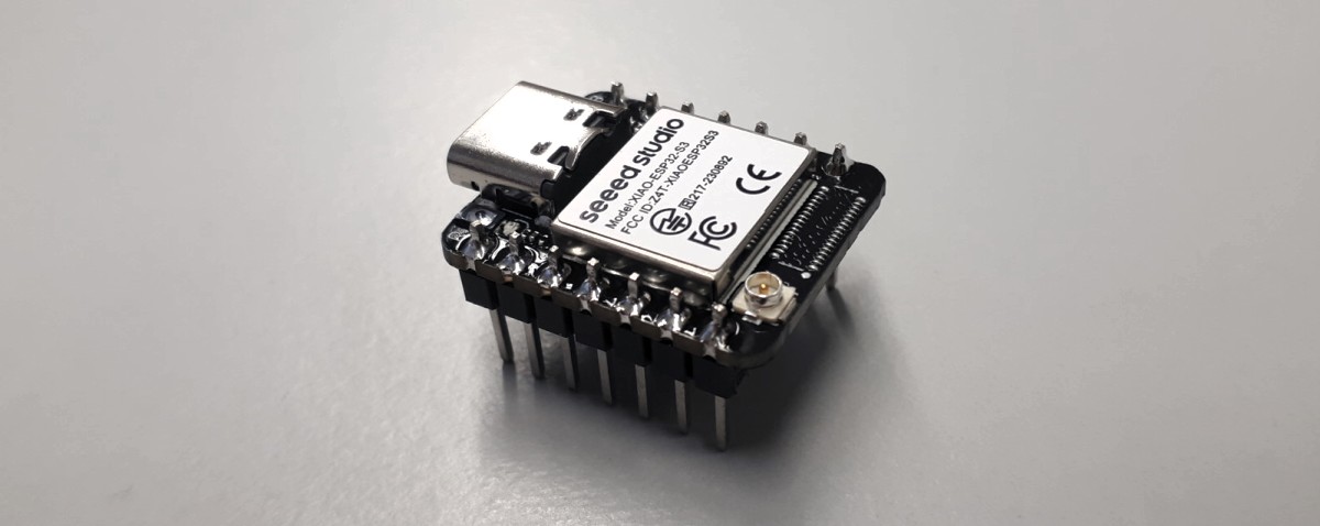
To read about the ESP32-S3, there were two resources considered: Xiao’s website and the data sheet by Espressif. Other resources were not considered here but may be relevant for later, such as the Hardware Design Guidelines for hardware integration and the Technical Reference Manual.
This chapter provides general information. It contains a functional block diagram as an overview and a list of features for Wi-Fi, Bluetooth, CPU, etc. The ESP32-S3 has an FPU and L1 cache. ROM is 384 KB (read-only memory), and SRAM is 512 KB. Furthermore, the ESP32-S3 includes strapping pins, which are used to configure the chip during startup or reset. Internal power management is present so batteries can be connected directly to the board.
It is possible to use external PSRAM of up to 8MB, an upgraded heat sink, an antenna, and/or a camera. Peripherals include GPIO, SPI, an LCD interface, UART, I2C, I2S, RMT, pulse counter, LED PWM, full-speed USB OTG, USB serial JTAG, two motor control PWM, SD/MMC host controller with 2 slots, general DMA, TWAI, JTAG for debugging, on-chip debug via JTAG, timers, and cryptographic hardware acceleration for SHA, AES, and RSA. Analog features include two 12-bit ADCs, temperature sensors, and touch sensors. The ESP32-S3 does not have a DAC. For the final project, PWM must be used for audio output or an external DAC. Digital output is 3.3V. The chip also has external clock input/output, which might be useful for synchronizing when working with multiple components.
The MCU can be configured to power up different power domains of the chip to achieve the best balance between chip performance, power consumption, and wakeup latency. Interrupts can be configured to be level-triggered or edge-triggered, timer-triggered, software-triggered, etc. To do those configurations, one writes specific values into the corresponding system registers. The ESP32-S3 supports radio and Wi-Fi and Bluetooth LE.
The recommended input voltage for all pins is typically 3.3 V. For information on voltage deviation, the tables must be checked. ADC characteristics, current consumptions, and Wi-Fi radio characteristics are included.
A Simple Arduino Blinking Program
For this assignment, we should demonstrate basic programming skills using a simulator, such as Wokwi. I did not have enough time for actually implementing a DSP algorithm with FAUST as described above. Instead, I just made an LED blink. For a week more focussed on programming, see week 11.


The following code sets up the serial communication for the MCU and configures pin 9 to be an output pin. The function analogWrite configures the pin to output a PWM signal and the second variable specifies the dutycycle with 255 meaning a value of 1 for 100% of the time. This is controlled using the variable brightness. It ramps up from 0 to 255 and then goes back to 0. The value of brightness is printed to the serial monitor.
 1static int brightness = 0;
 2
 3void setup() {
 4  // put your setup code here, to run once:
 5  Serial.begin(115200);
 6  Serial.println("Hello, ESP32-S3!");
 7  pinMode(9, OUTPUT);
 8}
 9
10void loop() {
11  analogWrite(9, brightness);
12  if (brightness == 255) {
13    brightness = 0;
14  } else {
15    brightness++;
16  }
17  delay(3);
18  Serial.println(brightness);
19}
In the below video, the running simulation can be seen. One can observe a slight ramping-up of the brightness of the LED, although it is not as clearly to see that.
For communicating with another device, I refer to my assignment in week 9 where I received sensor data from an inertia measurement unit (IMU) via UART.
Fabricating a Programmer
In week 11, I fabricated a Quentorres for myself using the knowledge from the electronics production week. This board serves as a programmer for different programming standards (JTAG, SWD, etc.).

.png files.

Reflections
What I Learned
This week for me was mostly about learning the background of embedded programming. How to put code on an MCU, what are the corresponding protocols? I also learned technical details about how to do DSP, in particular for audio on an MCU and what technical requirements persist for that.
What Went Wrong
Due to two exams I had this week, I was not able to get to run code on the ESP32, in particular I did not get to try out running DSP code generated from FAUST on it. Apart from that, the documentation was not finished until week 6. In the following weeks, I improved my time management in that respect.
What Went Well
The group assignment went very well. We worked together efficiently and shared tasks among each other in a reasonable way. Apart from that, Ferdi connected me with a friend him who has quite some experience with audio programming.
What I Would Do Differently
I would finish writing the documentation text as soon as possible, as I did in week 6.
Digitial Files
- Arduino sine blink
- Simple noise generation with FAUST
Use of Language Models
During writing this report, I used the following prompts asking ChatGPT 4o mini to form prose text from bullet points.
1Take the following bullet points and form prose text out of them. Do not add any additional information. Only use those words used in the bullet points and, additionally, those that are absolutely necessary to build grammatical sentences out of the bullet points. Formulate those things in past tense that are describing what has been done (like in a report) and those points that describe facts in present tense. Correct spelling mistakes. Preserve markdown hyperlinks:
2
3<insert bullet points>