Electronics Production
This week, I helped with the group assignment and printed my own PCB. Then, I tested my PCB. We have a new PCB machine, so I played a role in setting it up. The other Fab Academy students in our lab and I were the only ones to use and document this new machine. It is more effective than our previous machine, as it is capable of making a PCB more precisely and easily with its vacum that holds the cupper plates still on one position, preventing them from moving. Also, this machine has a mechanism that makes the adjustment of the z-axis more precisely.You can see our group assignment with this link
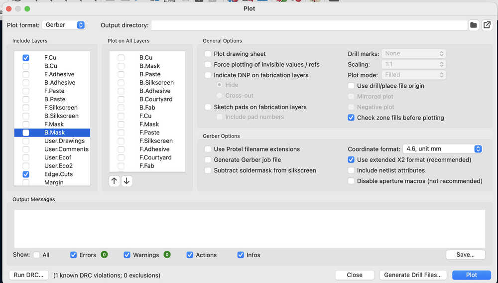
This week, I printed the board that I had designed in the electronics design week. First of all, I downloaded the gerber files on KiCAD. I only needed F.cu and Edge.Cuts layers. The following image shows the settings I used when downloading the gerber files.
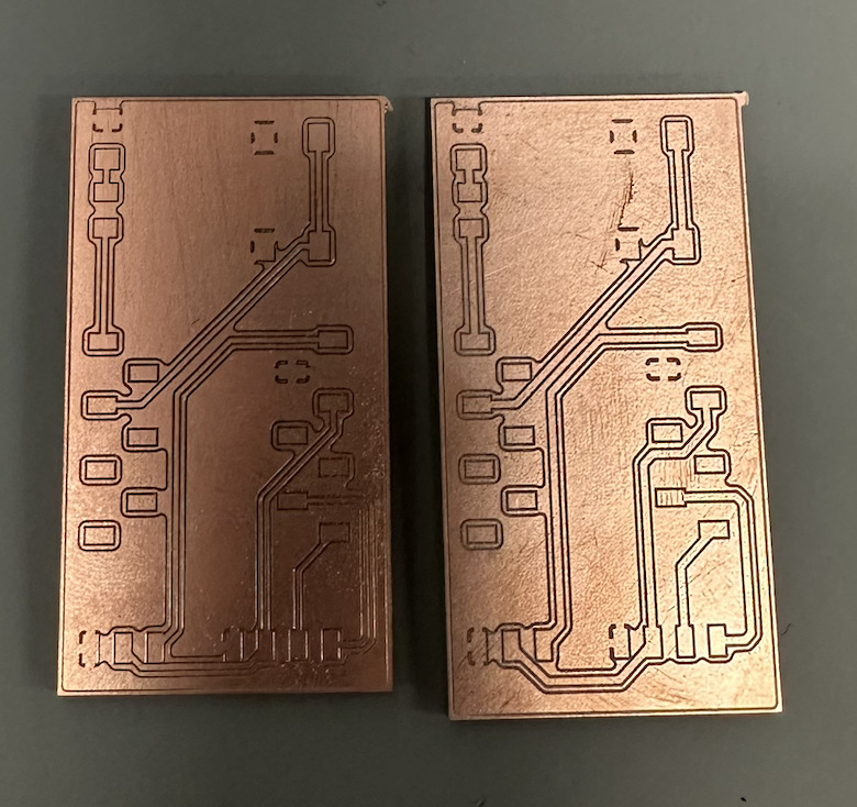
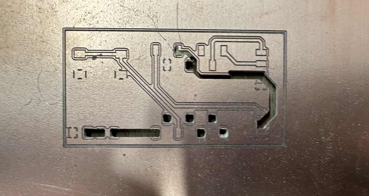
However, because my first design had thin tracks, I printed both versions. The one on the left shows the PCB with thin tracks and the other one shows the one that has the right size of tracks.
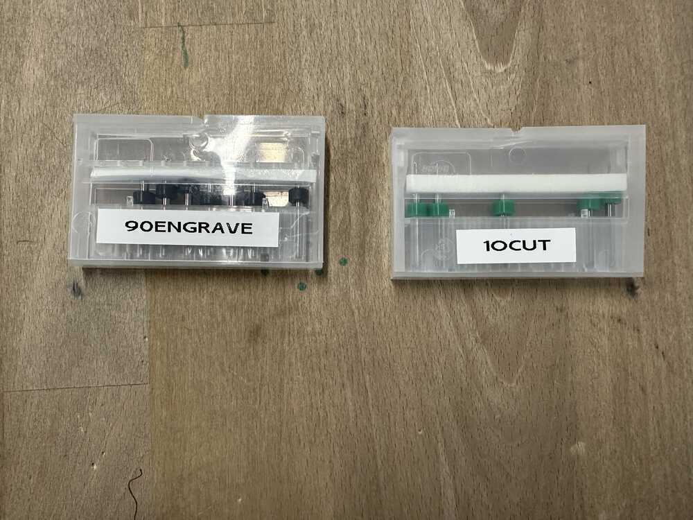
I used screws with 0.9 mm of diameter for engraving and 1 mm of diameter for cutting.
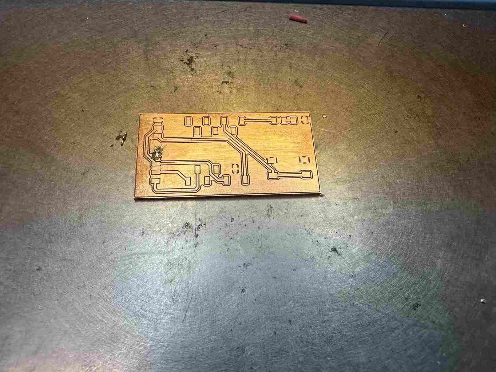
I also failed many times while cutting. For example, I forgot to change the screws, so the machine cut the PCB with the engraving screw. An example of my failures is the following image.
Soldering
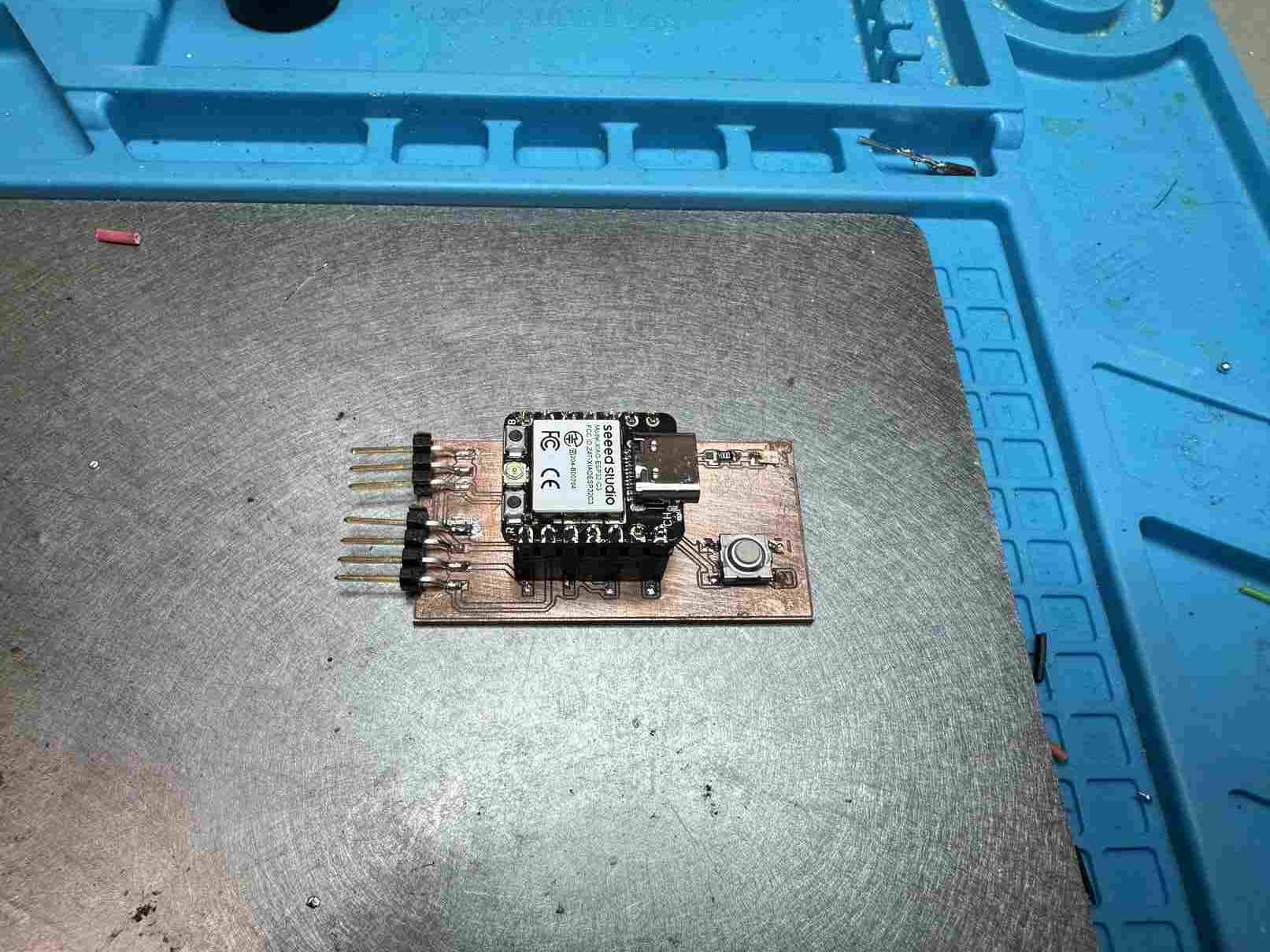
After cutting my PCB, I soldered the components onto it.
Components I Used
The following is a list of components I used on my PCB:
- Seeed Studio Xiao ESP32-C3
- LED Orange Clear 1206 SMD
- 100 ohm Resistor 1206
- Switch Tactile spst-no 0.05 A 24V
- Connector Header with three pins and five pins
Using a Multimeter
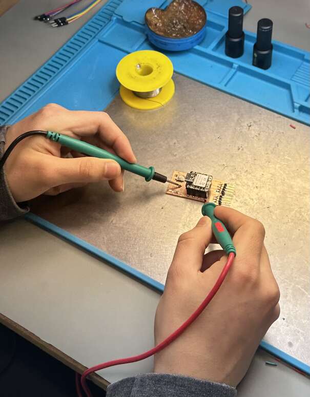
I used a multimeter very frequently to check whether the connections that are supposed to connect are connected and the connections that are not supposed to connect are not connected. When I touched two connected sides
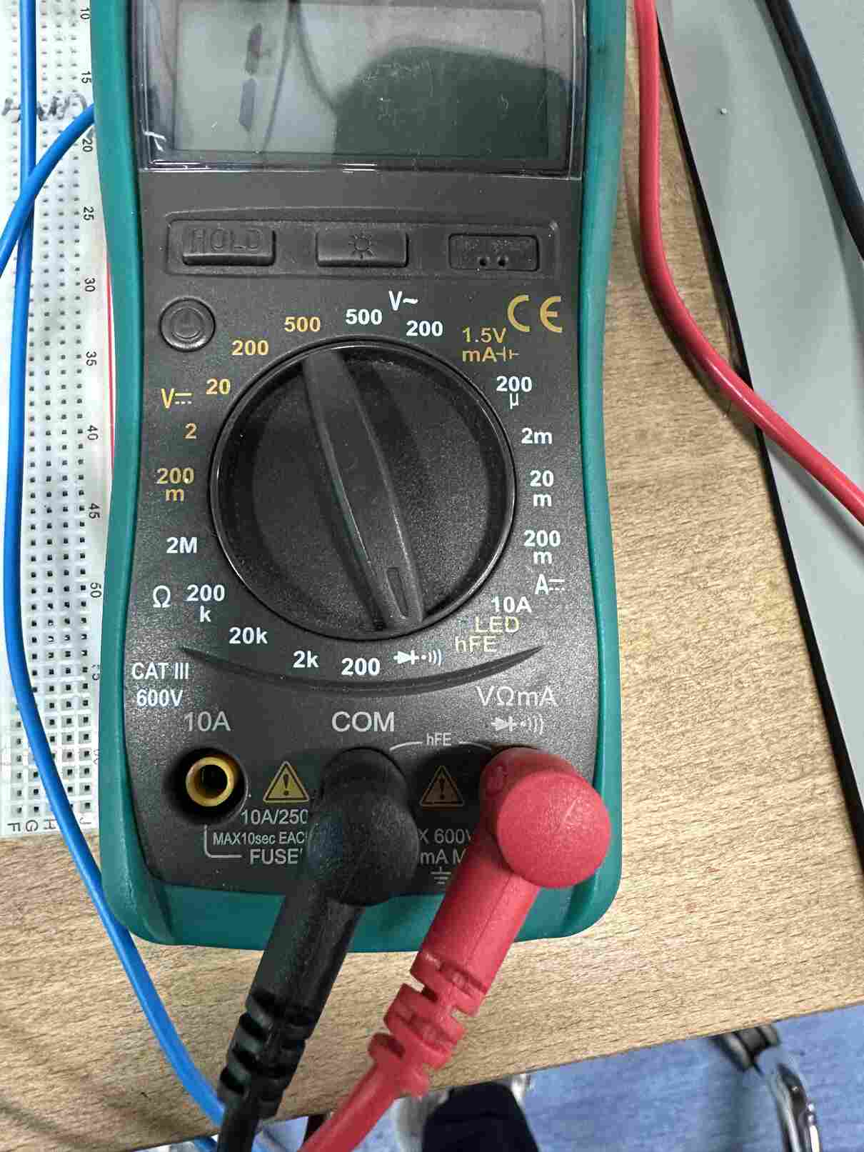
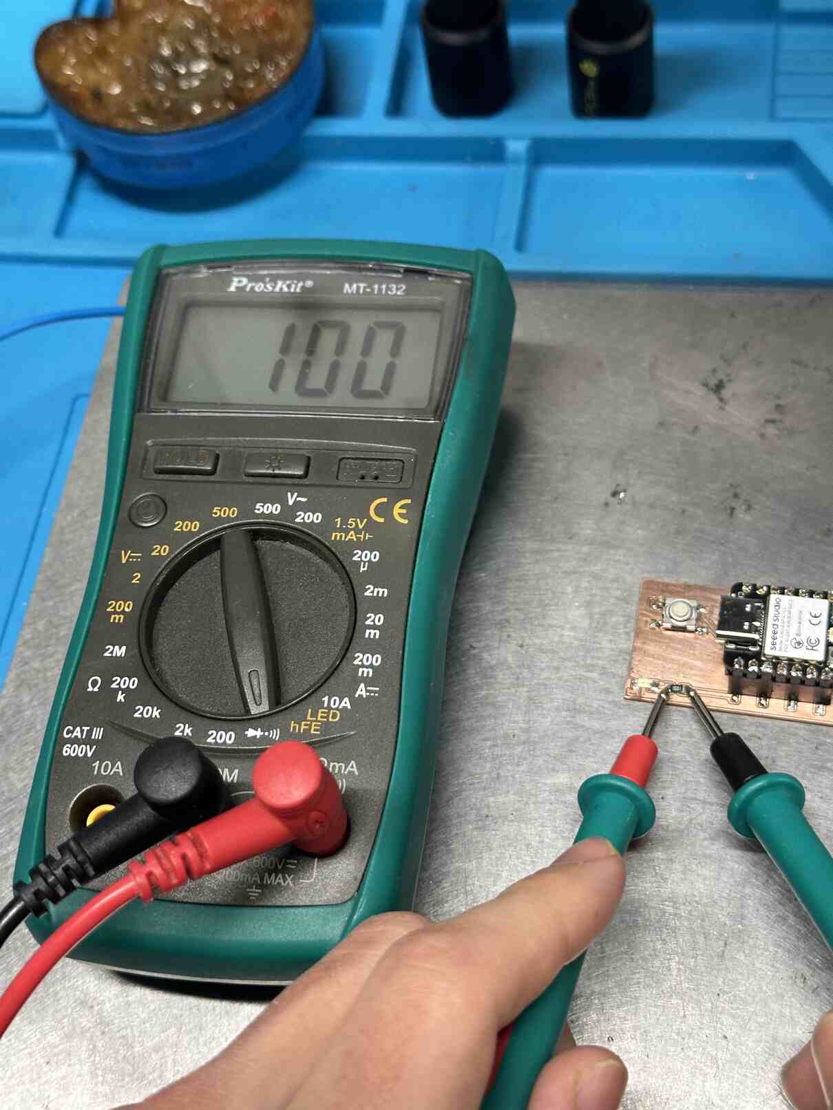
Then, I tested my resistor. When I touched both sides of my resistor, the multimeter showed the resistance of the resistor.
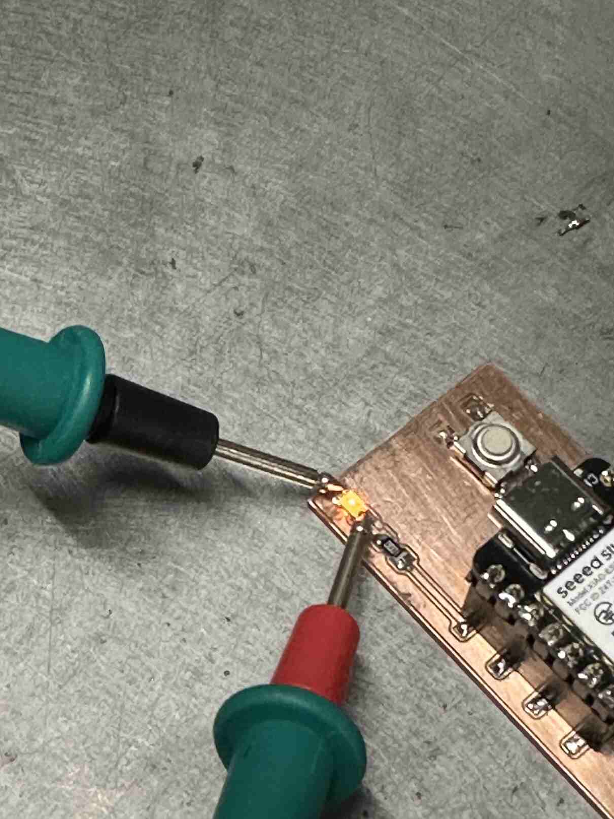
Afterward, I touched one part of the LED with the anode of the multimeter and the other part with the cathode part. It lid up, confirming that I touched the right sides with the right sides of the multimeter.
Fails
I also failed in my first trial of soldering. A solder bridge formed under the components, causing a short-circuit.