Computer Controlled Machining
This week, I used the CNC machine in my lab. I hadn't used a CNC machine before, so for the group assignment, our group assignment leader Ismail showed us how to use the CNC machine. We also completed our lab's safety training. Then, adjusting the settings of the CNC, such as speeds, materials, and allignment, we cut a test design.
You can see our group assignment with this link
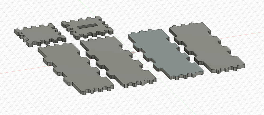
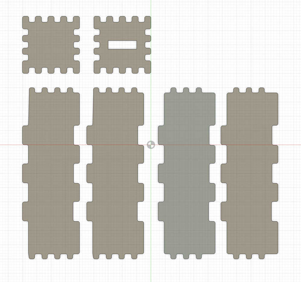
For this week's individual assignment, I cut and assembled a ballot box. First I designed it with Fusion 360. I first sketched a square with a side of 1000 mm as I would use a plywood with these dimensions. To design the base of my ballot box, I sketched another square with a side of 200 mm. Afterward, I designed three finger joints for the two sides and four finger joints for the remaining two. I designed the depths with 21 mm because the plywood I used had a thickness of 18 mm, and I left a tolerance of 3 mm to fit the joints together. I chose 3 mm as my tolerance because the other lab members had used it that way, and their design had worked.
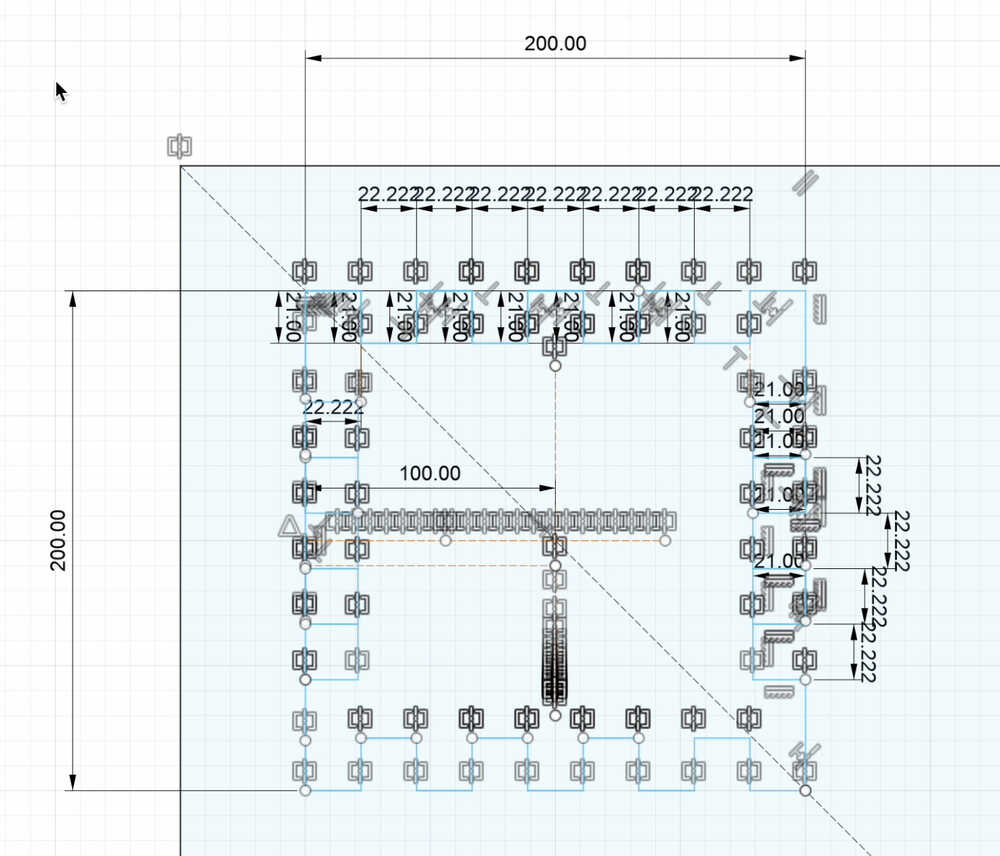
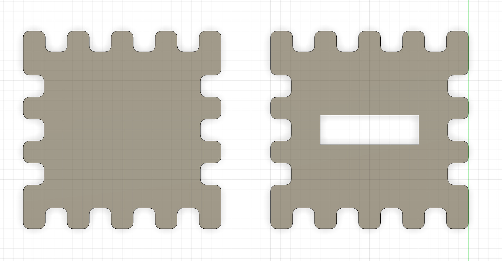
Then, I copied and pasted my sketch to make the ceiling of my ballot box. I also designed a cavity to throw papers into the box. Afterward, I added fillets with a diameter of 6 mm to the corners as I was going to use a metric 6 screw to cut my box.
Afterward, I sketched a rectangle with sides 600 mm and 200 mm so that my box would have a height of 60 cm and the lateral surfaces would fit to the base and the ceiling. Then, I sketched four joints to fit into the base and ceiling with four joints. I also sketched three joints to fit the lateral surfaces together. I then copied and pasted this sketch.
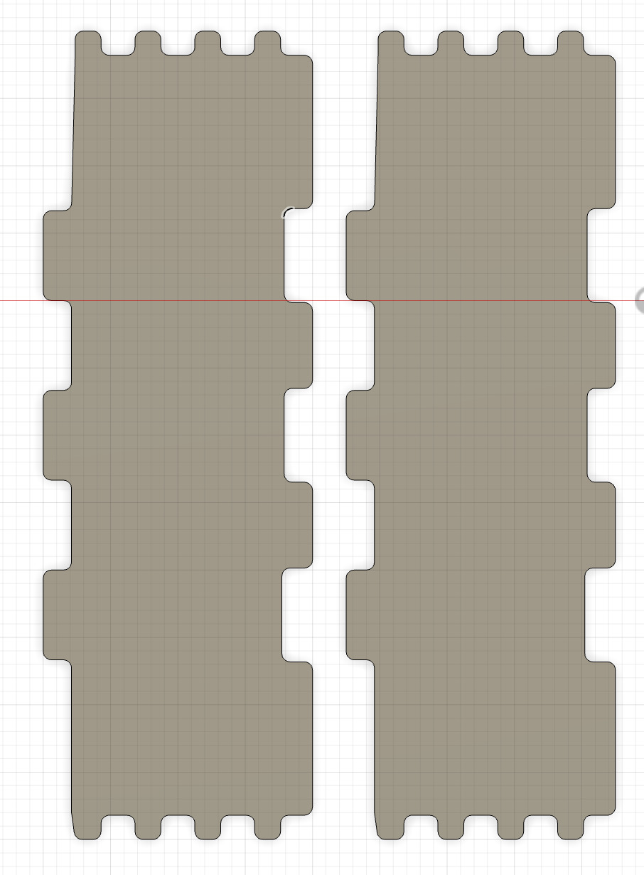
After sketching the lateral surfaces to fit into the base and ceiling with four joints, I designed the lateral surfaces for the bases with three joints.
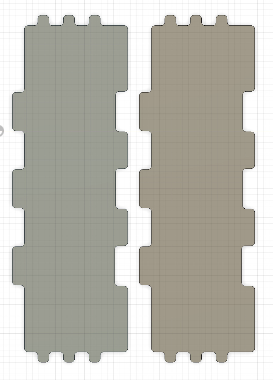
Now all the surfaces were ready.
Then, I gave my sketch a depth of 18 mm as it was the thickness of my wood.
I also drilled four holes with a diameter of 6 mm and a thickness of 18 mm to each piece so that I would stabilize the surface with a screw before cutting the hole thing.
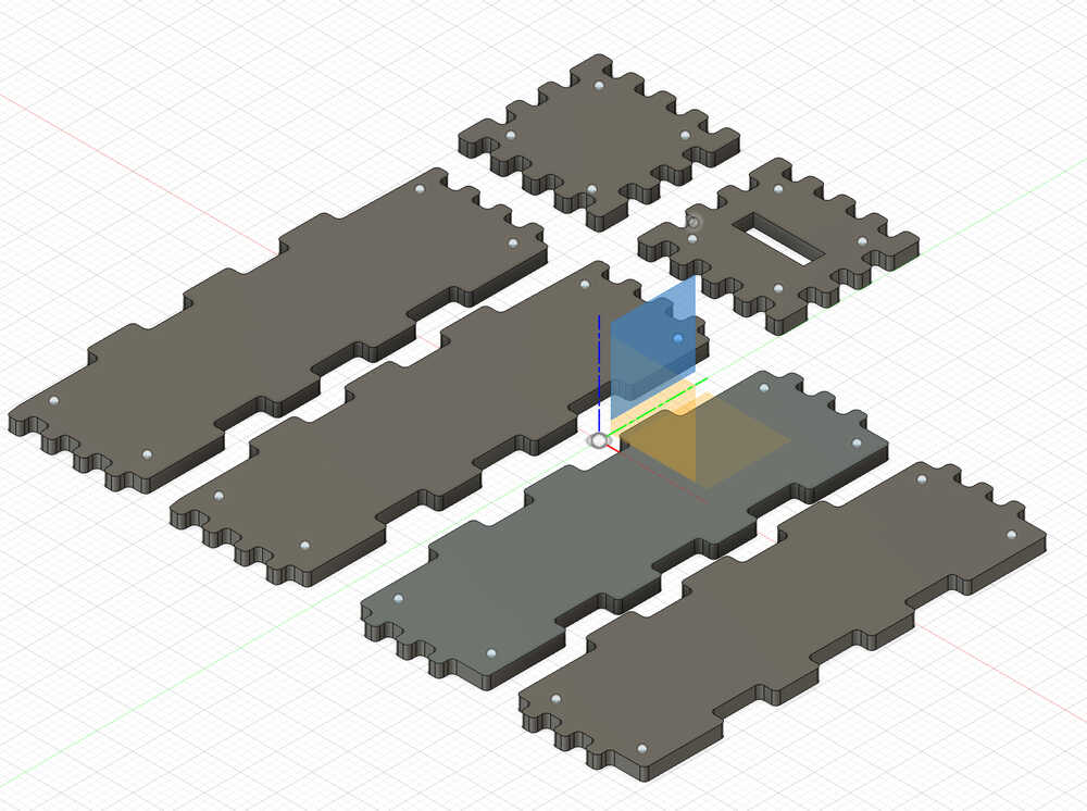
However, I realized that only two holes would be enough to stabilize a single piece instead of four.
Finally, after adjusting the settings in Fusion 360 for the CNC, I cut the pieces.
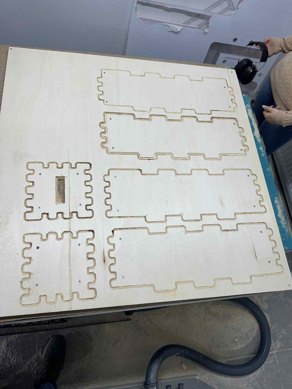
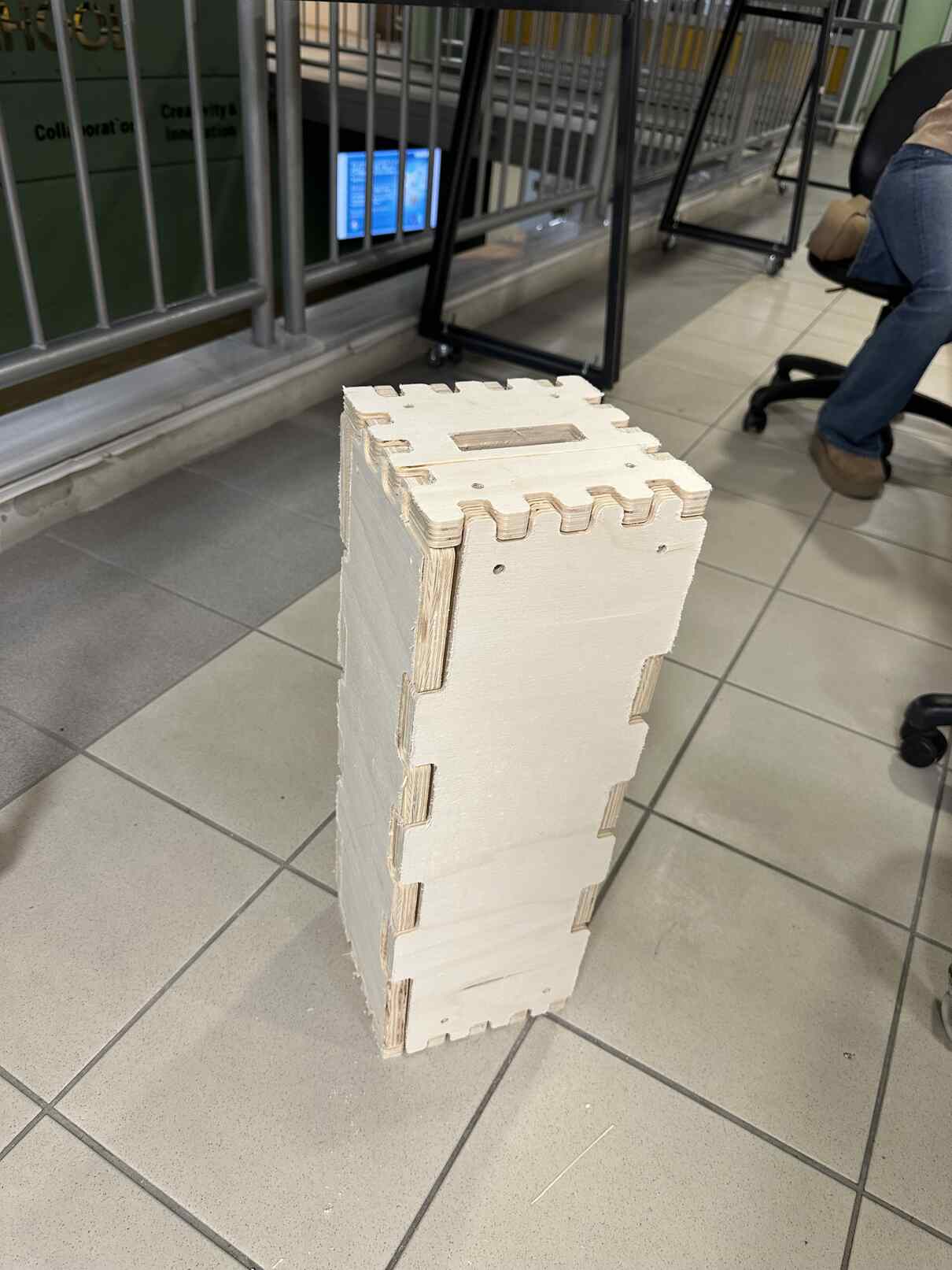
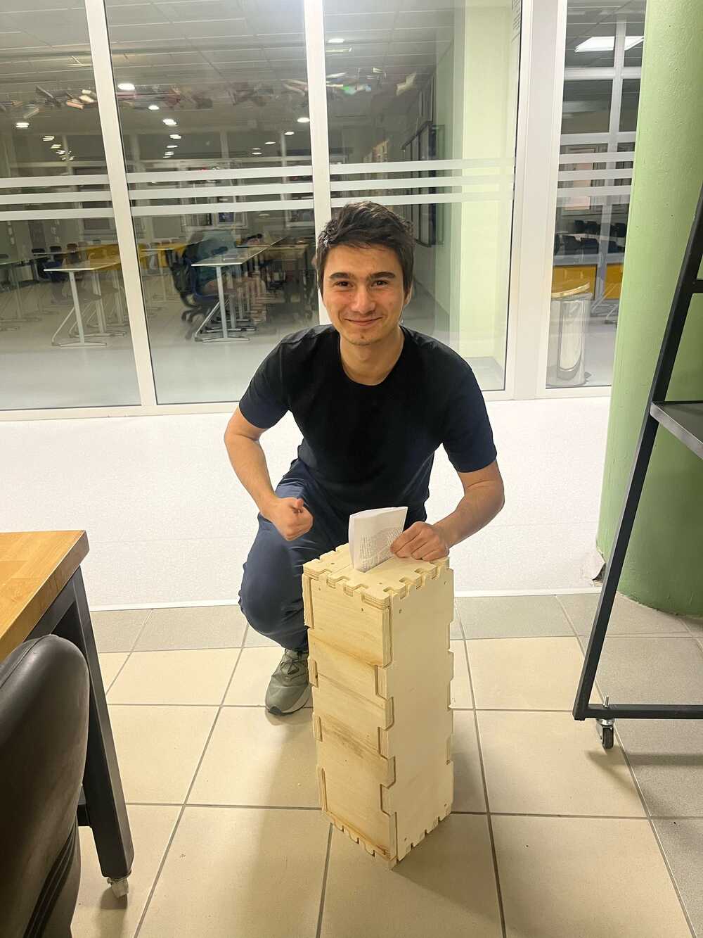
Then, I assembled my pieces. My final product looks like the followings:

CAM-toolpath
Now, I am going to talk about how I converted my design into a file that our CNC machine could process.
- Click on bodies and select "Create Components from Bodies"
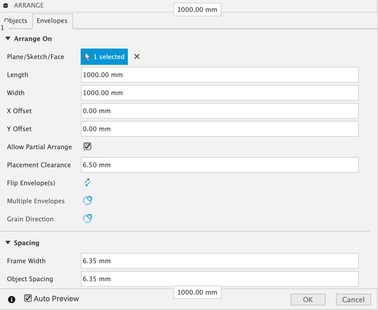
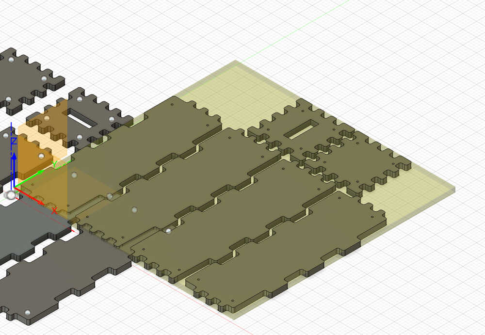
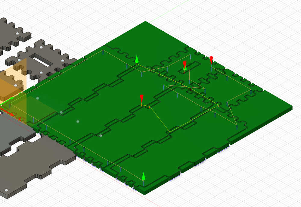
- Go to "Modify" and click on "Arrange." Select all the components that you want to cut.
- Go to "Envelopes" and sleect tha plane that your components stand on. The following image shows the settings.
- Now, go to the "Manufacture" section and click on "SETUP"
- Afterward, select only the new models (Setups).
- Click on "Stock" and arrange "Stock Top Offset" to be 0 mm.
- Then, go to "Setup" again, click on "Box Point" and select the corner.
- Click on "Drilling"
- Select Coolant as "Disabled"
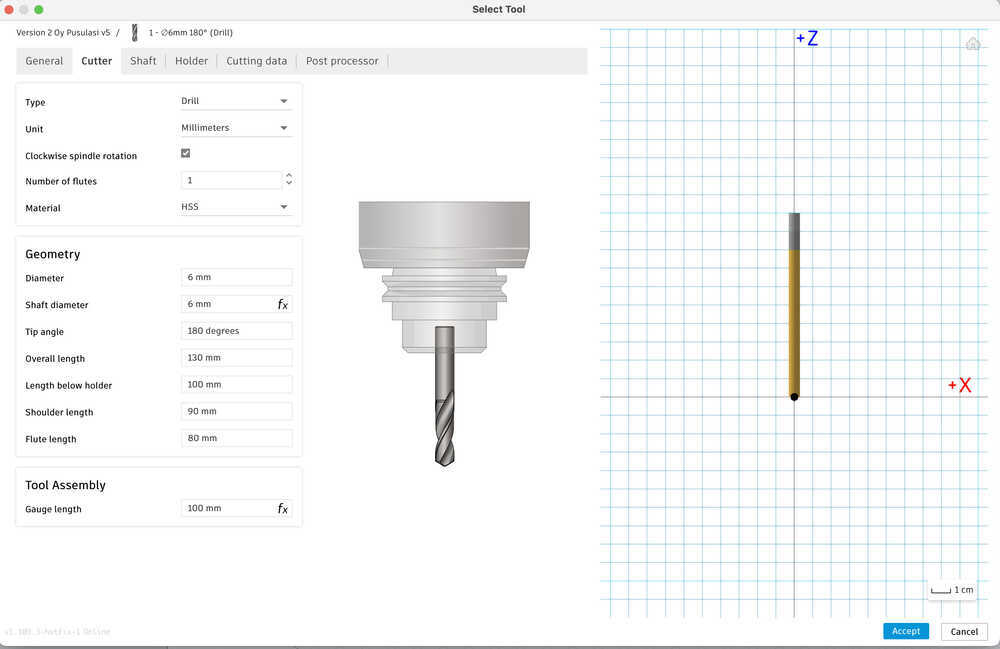
- Click on "Tool" and select New Tool.
- Arrange the following settings after clicking on Drill.
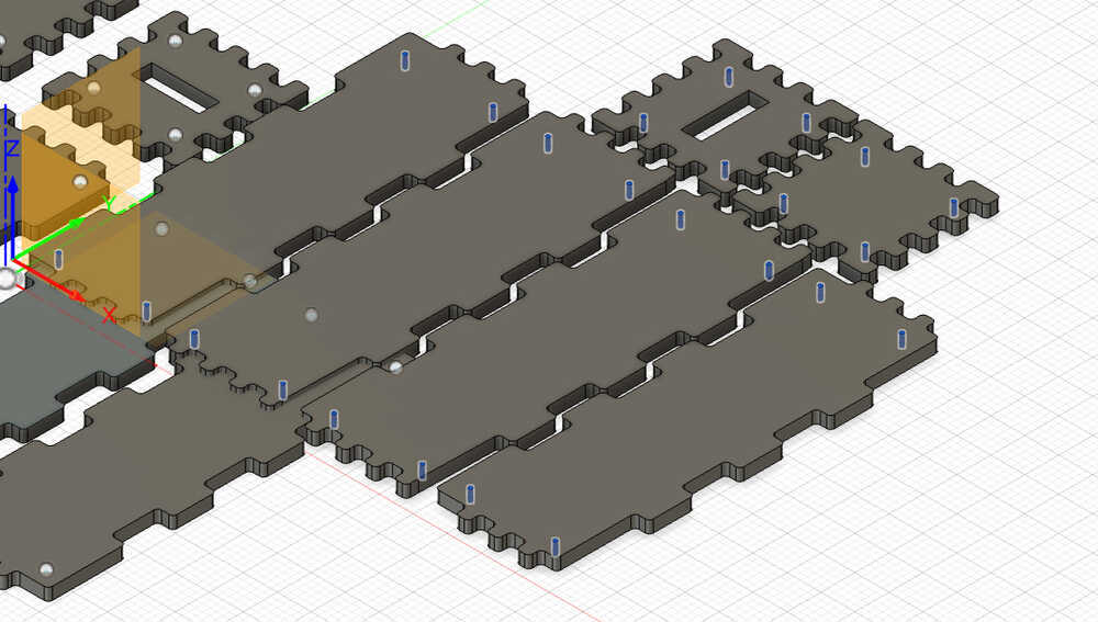
- Click on "Geometry," which is under the Drill panel.
- Arrange the Selection Mode as Selected Faces and select the 6mm holes
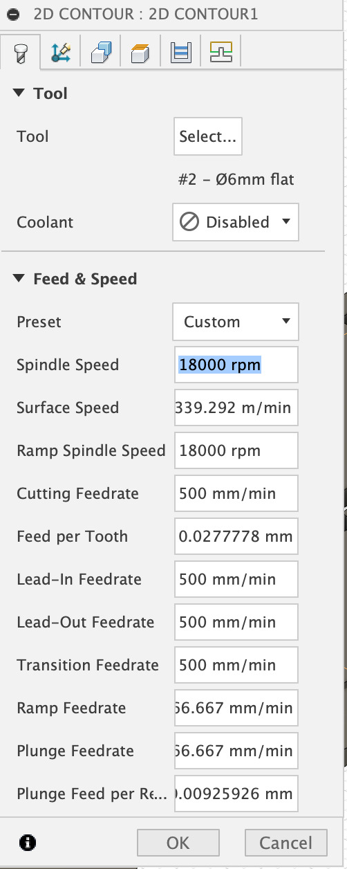
- Click on "2D" and select "2D Contour"
- Now select Flat end Mill and apply the same drilling settings.
- Set the Spindle Speed to be 18000 rpm and the Cutting Feedrate to be 800 mm/min, and disable coolant. The settings for the 2D Countour are the following.
- Select the bottom of the inside cutouts. It is important to cut the inside of the tools first in order to stabilize the cutting process.
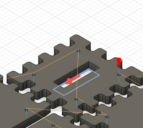
- Apply the same settings to make the second contour.
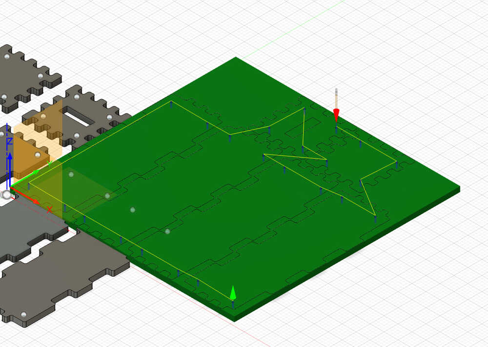
- Select the bottom outline of each design that you want to cut.
- Now, right click on your setup.
- Click on "Simulate"
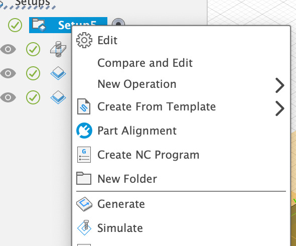
- Finally, right click on the setup folder and click on "Create NC Program"
You can access my 3D design through these zip files:

  STEP File
  f3d File