Introduction
This week, I had the opportunity to experiment with the Raspberry Pi Pico. The most significant aspects of this experience were reading Datasheets and understanding how a microcontroller works: what are it's pins used for, what type of pins are there. I also contributed to the group assingment by documenting how to download Thonny, Arduino, and VS Code. I also blinked the LED on Pico and documented it.
This is the link to our group project
Simulation
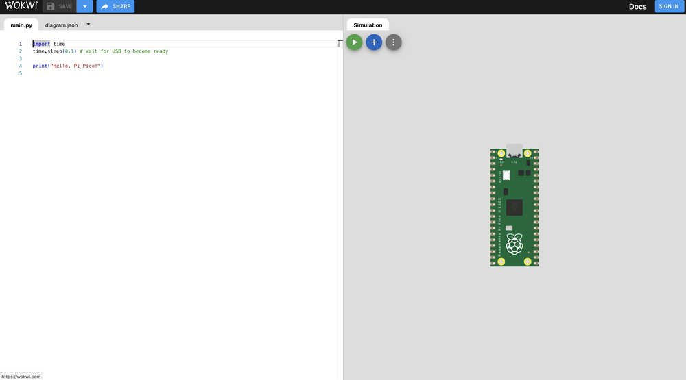
This week to simulate embedded programming I used the Wokwi simulation environment to control a Raspberry Pi Pico to get the hang working with some of the electronic components. Wokwi is a web based embedded programming environment. Steps to open Wokwi:
- search wokwi pico, micropython in your browser of choice
- click the first link that pops up
- the Wokwi micropython simulation environment appears!
Here, I decided the create a circuit which involved some fundamental electronics components.
Electronics
Bill of Materials (BOM)
| Component | Quantity | Description |
|---|---|---|
| Raspberry Pi Pico | 1 | Microcontroller |
| Red LED | 1 | Visual indicator |
| Yellow LED | 1 | Visual indicator |
| Green LED | 1 | Visual indicator |
| Push Button | 1 | User input trigger |
| Servo Motor (SG90 or similar) | 1 | Servo |
| Jumper Wires | Various | Connections |
| Breadboard | 1 | Circuit assembly |
Wiring
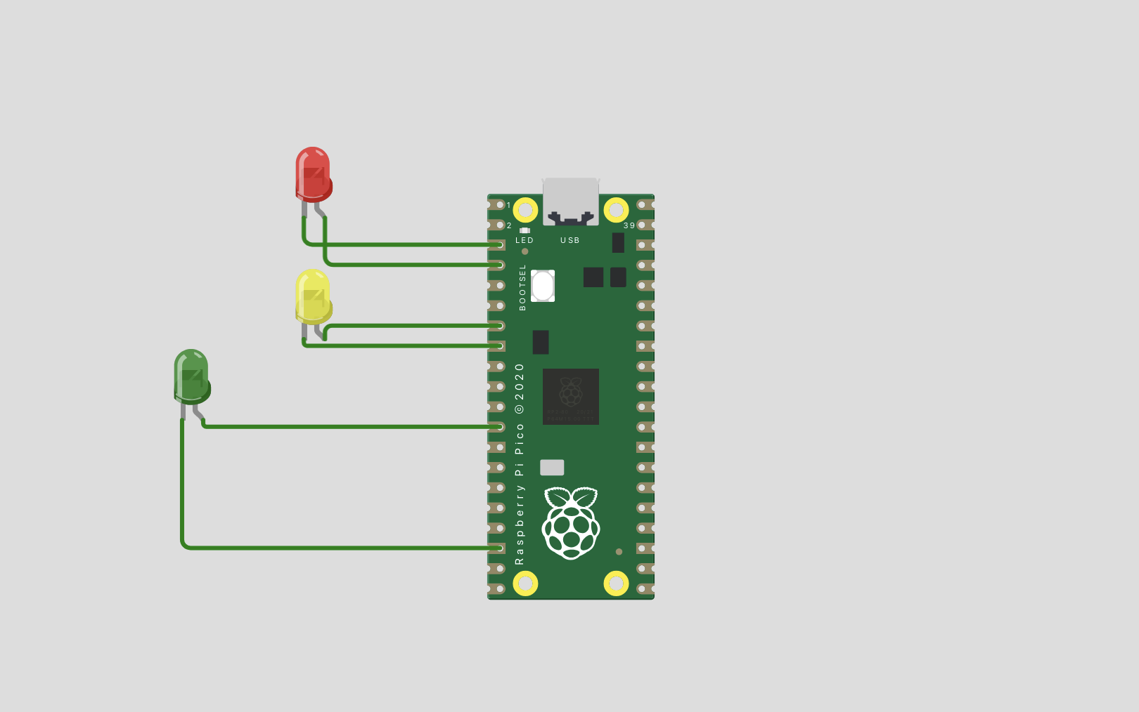
In the environment I firstly decided to wire the LED's and tried to create a system similar to traffic lights. I wired red, yellow, green LED's to GP (general purpose) pins 2,5 and 9 respectively. !
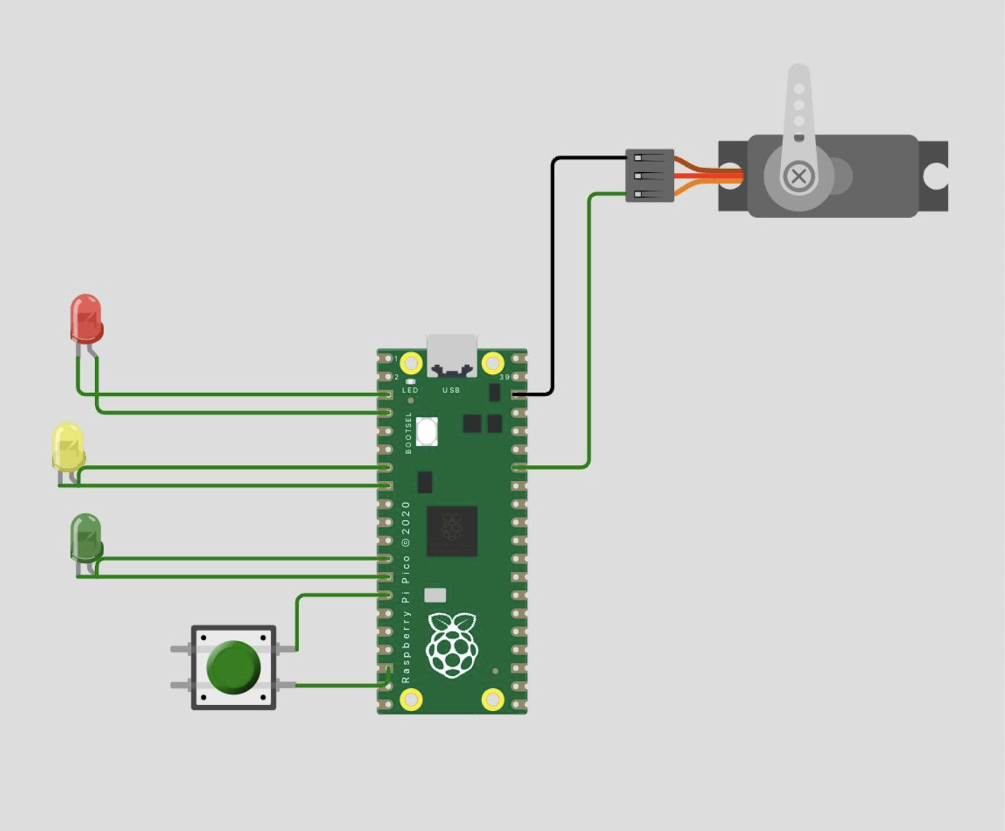
After getting this system to work, I added a Servo into the mix which would rotate from 0-160 and 160-0 in a continuous loop. I connected the servo to GP 28 on the opposite side of the board and LED's!

Lastly, I added a push button in order for it to serve as a initiator to the program so that it wouldn't run at the start every time.
Programming
Code Overivew
  from machine import Pin, PWM
  import time

  # Pin definitions for hardware connections
  RED_LED_PIN = 2      # Red LED connected to GPIO 2
  YELLOW_LED_PIN = 5   # Yellow LED connected to GPIO 5
  GREEN_LED_PIN = 9    # Green LED connected to GPIO 9
  SERVO_PIN = 28       # Servo motor signal connected to GPIO 28
  BUTTON_PIN = 10      # Push button connected to GPIO 10

  # Initialize LED pins as digital outputs
  red_led = Pin(RED_LED_PIN, Pin.OUT)
  yellow_led = Pin(YELLOW_LED_PIN, Pin.OUT)
  green_led = Pin(GREEN_LED_PIN, Pin.OUT)

  # Initialize servo with PWM at 50Hz (standard servo frequency)
  servo = PWM(Pin(SERVO_PIN))
  servo.freq(50)

  # Initialize button with internal pull-up resistor
  # When button is pressed, it will read LOW (0)
  button = Pin(BUTTON_PIN, Pin.IN, Pin.PULL_UP)

  def turn_on_led(led_pin):
     """
     Turn on specified LED and ensure others are off
     Args:
         led_pin: GPIO pin number of LED to turn on
     """
     red_led.value(led_pin == RED_LED_PIN)
     yellow_led.value(led_pin == YELLOW_LED_PIN)
     green_led.value(led_pin == GREEN_LED_PIN)

  def servo_movement(angle):
     """
     Move servo to specified angle
     Args:
         angle: Desired angle between 0 and 180 degrees
     """
     # PWM duty cycle values for 0° and 180°
     # These values may need adjustment based on your specific servo
     min_duty = 1638  # Duty cycle for 0 degrees (1/20 * 65535)
     max_duty = 8192  # Duty cycle for 180 degrees (5/20 * 65535)

     # Ensure angle is within valid range
     angle = max(0, min(180, angle))

     # Calculate duty cycle for desired angle
     duty = int(min_duty + (angle / 180) * (max_duty - min_duty))
     servo.duty_u16(duty)

  # Define movement sequence
  # Moves from 0° to 160° and back in 20° increments
  ANGLE_SEQUENCE = [0, 20, 40, 60, 80, 100, 120, 140, 160,
                  160, 140, 120, 100, 80, 60, 40, 20, 0]

  # Create LED sequence that cycles through all three LEDs
  # Length matches ANGLE_SEQUENCE by repeating pattern
  LED_SEQUENCE = [RED_LED_PIN, YELLOW_LED_PIN, GREEN_LED_PIN] * (len(ANGLE_SEQUENCE) // 3)

  try:
     while True:
         # Wait for button press
         if button.value() == 0:
             time.sleep(0.05)  # Debounce delay

             # Wait for button release
             while button.value() == 0:
                 pass

             # Execute movement sequence
             for i in range(len(ANGLE_SEQUENCE)):
                 turn_on_led(LED_SEQUENCE[i])      # Update LED
                 servo_movement(ANGLE_SEQUENCE[i])  # Move servo
                 time.sleep(1)                      # Wait 1 second

  except KeyboardInterrupt:
     # Clean up on program exit
     servo.duty_u16(0)  # Stop servo
     red_led.value(0)   # Turn off all LEDs
     yellow_led.value(0)
     green_led.value(0)
Mistakes and What I Learned
MicroPython Code Breakdown: LED and Servo Control System
1. Imports and Pin Definitions
  from machine import Pin, PWM
  import time

  RED_LED_PIN = 2
  YELLOW_LED_PIN = 5
  GREEN_LED_PIN = 9
  SERVO_PIN = 28
  BUTTON_PIN = 10
This section imports necessary modules and defines constants for GPIO pin assignments. The machine module provides hardware control capabilities, while time is used for delays.
2. Hardware Initialization
  red_led = Pin(RED_LED_PIN, Pin.OUT)
  yellow_led = Pin(YELLOW_LED_PIN, Pin.OUT)
  green_led = Pin(GREEN_LED_PIN, Pin.OUT)

  servo = PWM(Pin(SERVO_PIN))
  servo.freq(50)

  button = Pin(BUTTON_PIN, Pin.IN, Pin.PULL_UP)
This block initializes the hardware:
- LEDs are set up as digital outputs
- Servo is configured with PWM at 50Hz (standard servo frequency)
- Button is set up with an internal pull-up resistor (reads 1 when not pressed, 0 when pressed)
3. LED Control Function
def turn_on_led(led_pin):
  """
  Turn on specified LED and ensure others are off
  Args:
      led_pin: GPIO pin number of LED to turn on

  red_led.value(led_pin == RED_LED_PIN)
  yellow_led.value(led_pin == YELLOW_LED_PIN)
  green_led.value(led_pin == GREEN_LED_PIN)
  """
This function implements mutually exclusive LED control:
- Takes a pin number as input
- Uses boolean comparisons to ensure only one LED is on at a time
- Elegant implementation avoiding multiple if-statements
4. Servo Control Function
def servo_movement(angle):
  """
  Move servo to specified angle
  Args:
      angle: Desired angle between 0 and 180 degrees
  """
  min_duty = 1638  # Duty cycle for 0 degrees (1/20 * 65535)
  max_duty = 8192  # Duty cycle for 180 degrees (5/20 * 65535)

  angle = max(0, min(180, angle))
  duty = int(min_duty + (angle / 180) * (max_duty - min_duty))
  servo.duty_u16(duty)
The servo control function:
- Converts angles (0-180°) to appropriate PWM duty cycles
- Includes bounds checking for safety
- Uses linear interpolation to calculate duty cycle
- Works with 16-bit PWM resolution (0-65535)
5. Movement Sequences
ANGLE_SEQUENCE = [0, 20, 40, 60, 80, 100, 120, 140, 160, 160, 140, 120, 100, 80, 60, 40, 20, 0]

LED_SEQUENCE = [RED_LED_PIN, YELLOW_LED_PIN, GREEN_LED_PIN] * (len(ANGLE_SEQUENCE) // 3)
Defines the movement patterns:
- ANGLE_SEQUENCE creates a sweep pattern (0° → 160° → 0°)
- LED_SEQUENCE cycles through the LEDs in sync with servo movement
- Multiplication operator creates a pattern matching ANGLE_SEQUENCE length
6. Main Control Loop
  while True:
      if button.value() == 0:
          time.sleep(0.05)  # Debounce delay

          while button.value() == 0:
              pass

          for i in range(len(ANGLE_SEQUENCE)):
              turn_on_led(LED_SEQUENCE[i])
              servo_movement(ANGLE_SEQUENCE[i])
              time.sleep(1)

except KeyboardInterrupt:
  servo.duty_u16(0)
  red_led.value(0)
  yellow_led.value(0)
  green_led.value(0)
The main program loop:
- Waits for button press with debouncing
- Executes the movement sequence when triggered
- Includes cleanup code for graceful shutdown
- Uses try-except to handle program termination
Technical Details
PWM Calculations
- The servo uses a 50Hz signal (20ms period)
- Duty cycle range: 1638 (2.5%) to 8192 (12.5%)
- These values correspond to typical servo pulse widths:
- 0° position: 0.5ms pulse (2.5% duty)
- 180° position: 2.5ms pulse (12.5% duty)
Button Debouncing
- 50ms delay after button press detection
- Waits for button release before continuing
- Prevents multiple triggers from a single press
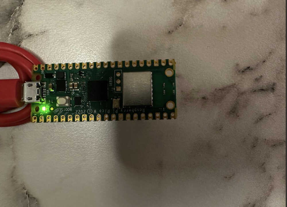
Extra Credit: Working with a Development Board
After completing the main assignment of this week I had a chance to experiment with a Raspberry Pi Pico in real life. I decided to try to light the LED on the Pico's board, I used the picozero libraries pico_led class for this below is the code implementations and result:
  from picozero import pico_led
  from time import sleep

  pico_led.on()
  sleep(10)
  pico_led.off()