Week 15 — System Integration: Bandbox
Reflection
While designing Bandbox, I found that system integration is more than just connecting components — it's about creating a seamless experience. Balancing aesthetics, electronic functionality, and interactivity required a holistic approach. Simple decisions like servo placement had big effects on usability and structure.
Full System Description
Bandbox is an interactive music toy where pressing one of four buttons triggers a character’s LED, movement, and unique melody. Inspired by Incredibox, the device allows simultaneous button presses to build up a musical layer.
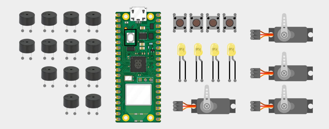
- 1x Raspberry Pi Pico W 2
- 4x Push Buttons (momentary)
- 4x LEDs (digital ON/OFF)
- 4x Servo motors (externally powered, 5V)
- 13x Passive buzzers (direct GPIO)
- Custom PCB with headers, no regulators or extra components
Each button controls 1 LED, 1 servo, and specific buzzers to play a sound or melody.
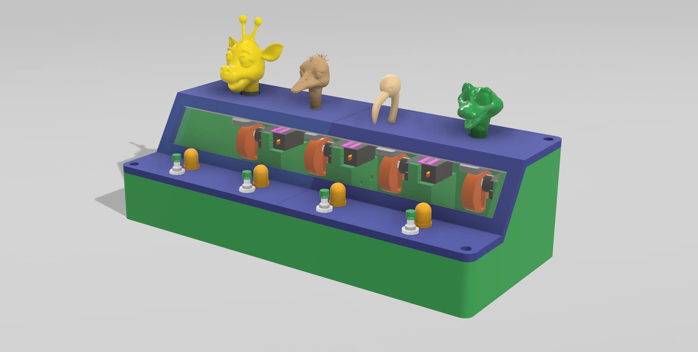
Rendered View
Below is a rendered image of the Bandbox system:
Integration Summary
- Direct GPIO connection for all components
- Servos powered externally via wall adapter
- Buzzers driven using MicroPython PWM
- Melodies coded manually with tone-duration pairs
User Interaction
- Buttons work on press-and-hold basis
- Multiple buttons can be pressed at once (polyphony)
- LEDs are ON/OFF only (no PWM)
- Servo motion loops while button is held
Physical Design & Fabrication
- PLA 3D printed body (4 parts combined into base and lid)
- 5mm clear acrylic panel (laser cut, glued to body)
- Assembly with M3 screws and brass inserts
- No sanding or painting applied
Packaging & Presentation
The system is designed to be visually self-contained and presentable. The transparent acrylic allows visibility into the electronics and mechanics without needing to open the device. One external cable supplies power; there are no loose wires or prototyping boards.
Documentation & Presentation Plan
- A short video will be created to show interaction and features
- Live demo during final presentation — user interaction enabled
Project Schedule
| Date Range | Focus & Tasks |
|---|---|
| May 10–17 | Initial CAD modeling, 3D printing tests, servo setup |
| May 18–24 | PCB design and production, wiring buttons, LEDs, servos |
| May 25–31 | Buzzer wiring, melody programming, multiple button logic |
| June 1–7 | Final assembly, acrylic mounting, full testing, photos/videos |
| June 8–10 | Buffer time, documentation finalization, video edit, prep |