Week 14. Interface and Application Programming
Group Assignment
Click to access the group assignmentThe goal of this week was to create an application that interfaces a user with an input and/or output device that I made. I used the circuit I had previously designed, which includes two LEDs and a buzzer connected to an ESP32-C3 (Seeed Studio XIAO).
I wanted to make the simplest possible web interface to control this board — without Processing, Node-RED, or external software. My plan was to use HTML buttons in a web page hosted directly on the ESP32.
System Architecture
      [Browser Interface]
              ⇅ HTTP
      [ESP32 Web Server]
              ⇅ GPIO
      [LED1, LED2, Buzzer]
What I Used
- ESP32-C3 XIAO
- 2x Mini LEDs
- 1x Buzzer
- Breadboard + Wires
- Wi-Fi access point
- Arduino IDE + WebServer library
How It Works
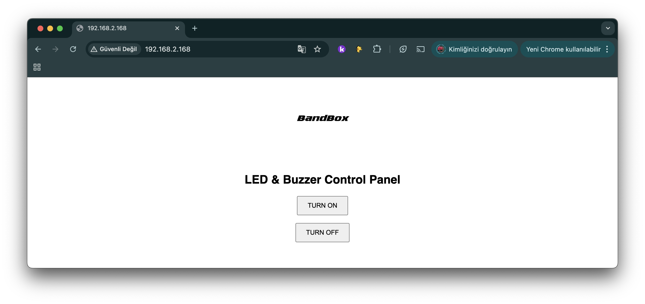
I connected the LEDs to GPIO 4 and GPIO 5, and the buzzer to GPIO 9. The ESP32 connects to my Wi-Fi network and starts a local web server. When I open the page in a browser, I see a simple interface with a logo and two buttons: "TURN ON" and "TURN OFF". These buttons send HTTP requests to the ESP32, which then controls the outputs accordingly.
Web Interface
The interface includes a logo I created, loaded from my Fab Academy page:
About the Code
- WiFi.begin(ssid, password);
Connects ESP32 to your Wi-Fi network. - WebServer server(80);
Starts the built-in web server on port 80. - #define LED1 4, LED2 5, BUZZER 9
Assigns GPIO pins for output devices. - server.on("/", handleRoot);
Displays the main page with logo and buttons. - server.on("/on", handleOn);
Turns on both LEDs and starts buzzer. - server.on("/off", handleOff);
Turns off LEDs and stops buzzer. - server.handleClient();
Keeps the server responding to browser requests. - handleRoot()
Sends HTML page with “TURN ON” and “TURN OFF” buttons. - handleOn()
Sets LEDs to HIGH, buzzer plays 1kHz tone. - handleOff()
Sets LEDs to LOW, stops buzzer sound.
Final Code
      #include <WiFi.h>
      #include <WebServer.h>

      const char* ssid = "Hisar_Superbox";
      const char* password = "P@ssw0rd";

      WebServer server(80);

      #define LED1 4
      #define LED2 5
      #define BUZZER 9

      void setup() {
        Serial.begin(115200);
        pinMode(LED1, OUTPUT);
        pinMode(LED2, OUTPUT);
        pinMode(BUZZER, OUTPUT);

        WiFi.begin(ssid, password);
        while (WiFi.status() != WL_CONNECTED) {
          delay(1000);
          Serial.println("Connecting to Wi-Fi...");
        }

        Serial.println("Connected to Wi-Fi!");
        Serial.print("ESP IP Address: ");
        Serial.println(WiFi.localIP());

        server.on("/", handleRoot);
        server.on("/on", handleOn);
        server.on("/off", handleOff);
        server.begin();
      }

      void loop() {
        server.handleClient();
      }

      void handleRoot() {
        String html = "<html><body style='text-align:center; font-family: sans-serif;'>";
        html += "<img src='https://fabacademy.org/2025/labs/hisar/students/ahmet-bas/images/logomogofalanfilanbandbox.png' width='150'><br><br>";
        html += "<h2>LED & Buzzer Control Panel</h2>";
        html += "<p><a href='/on'><button style='padding:10px 20px;'>TURN ON</button></a></p>";
        html += "<p><a href='/off'><button style='padding:10px 20px;'>TURN OFF</button></a></p>";
        html += "</body></html>";
        server.send(200, "text/html", html);
      }

      void handleOn() {
        digitalWrite(LED1, HIGH);
        digitalWrite(LED2, HIGH);
        tone(BUZZER, 1000);
        server.sendHeader("Location", "/");
        server.send(303);
      }

      void handleOff() {
        digitalWrite(LED1, LOW);
        digitalWrite(LED2, LOW);
        noTone(BUZZER);
        server.sendHeader("Location", "/");
        server.send(303);
      }
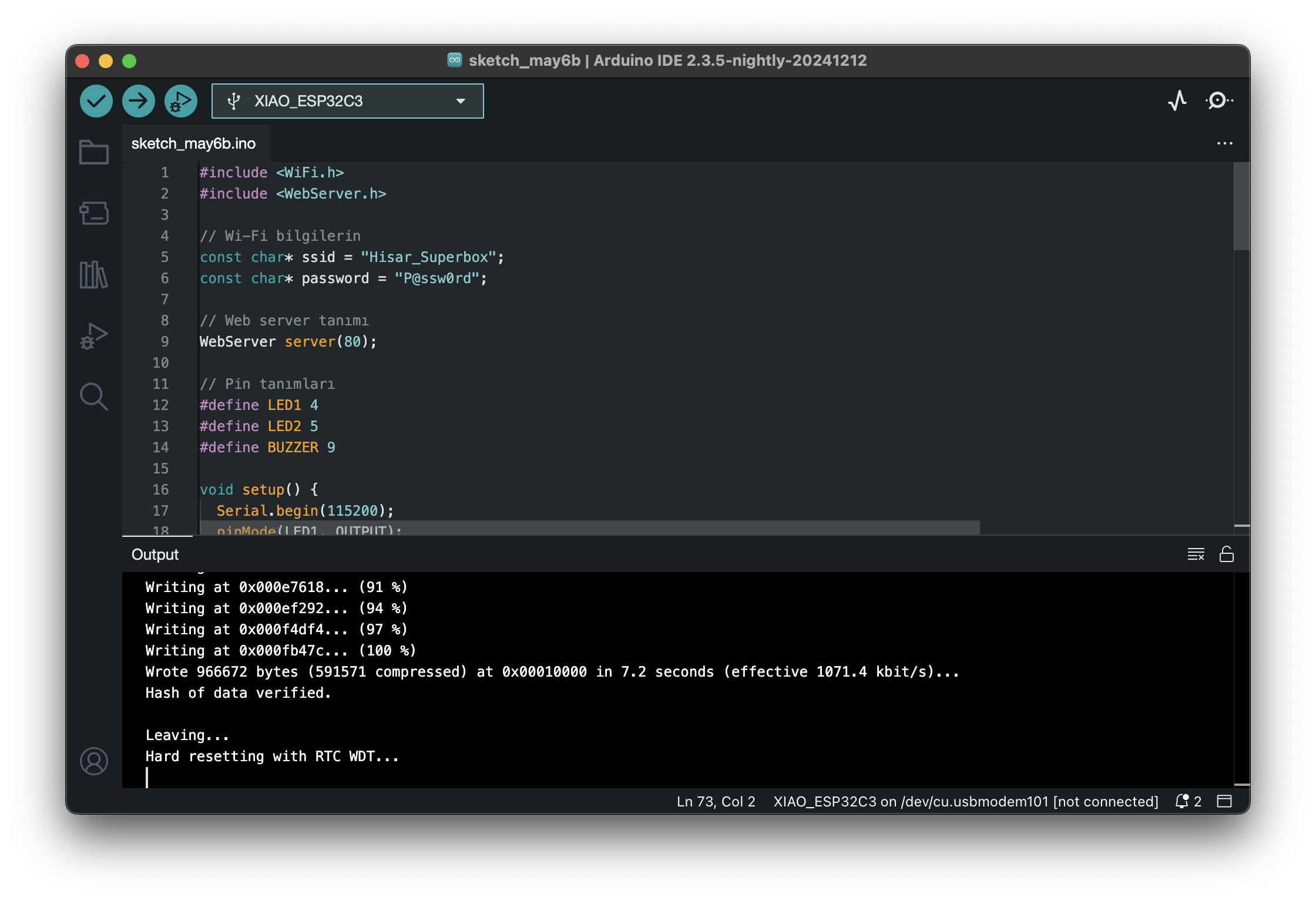
Uploading Code Using Arduino IDE
I used the Arduino IDE to program my ESP32-C3 board. Below are the steps I followed to set everything up and upload my code successfully.
Steps I Followed:
-
Installed the ESP32 board definitions:
Opened Arduino IDE → Preferences
Added this URL to “Additional Boards Manager URLs”:
https://raw.githubusercontent.com/espressif/arduino-esp32/gh-pages/package_esp32_index.json
Then went to Tools → Board → Boards Manager, searched for “esp32” and installed it. -
Selected the correct board:
Tools → Board → ESP32C3 Dev Module
(Or Seeed XIAO ESP32-C3 if listed) -
Selected the right port:
Tools → Port → [Your COM port]
Made sure the ESP32 board was connected via USB-C. - Pasted my code into the Arduino IDE editor.
- Clicked the Upload button (right-arrow icon in the IDE).
After Upload:
I opened the Serial Monitor at 115200 baud.
Once connected to Wi-Fi, I saw the assigned IP address.
I copied that IP into a browser to access my interface.
Heroshot and Video: