Week 5- 3D Scanning and Printing
Group Assignment
Click to access the group assignment
Vase — Design & 3D Printing Documentation
1. Project Overview
This project covers the creation of an organic, Voronoi-inspired vase form using Fusion 360’s parametric sketch and modeling tools, followed by printing on a Bambu Lab A1 with PLA filament.
2. Fusion 360 Design Steps
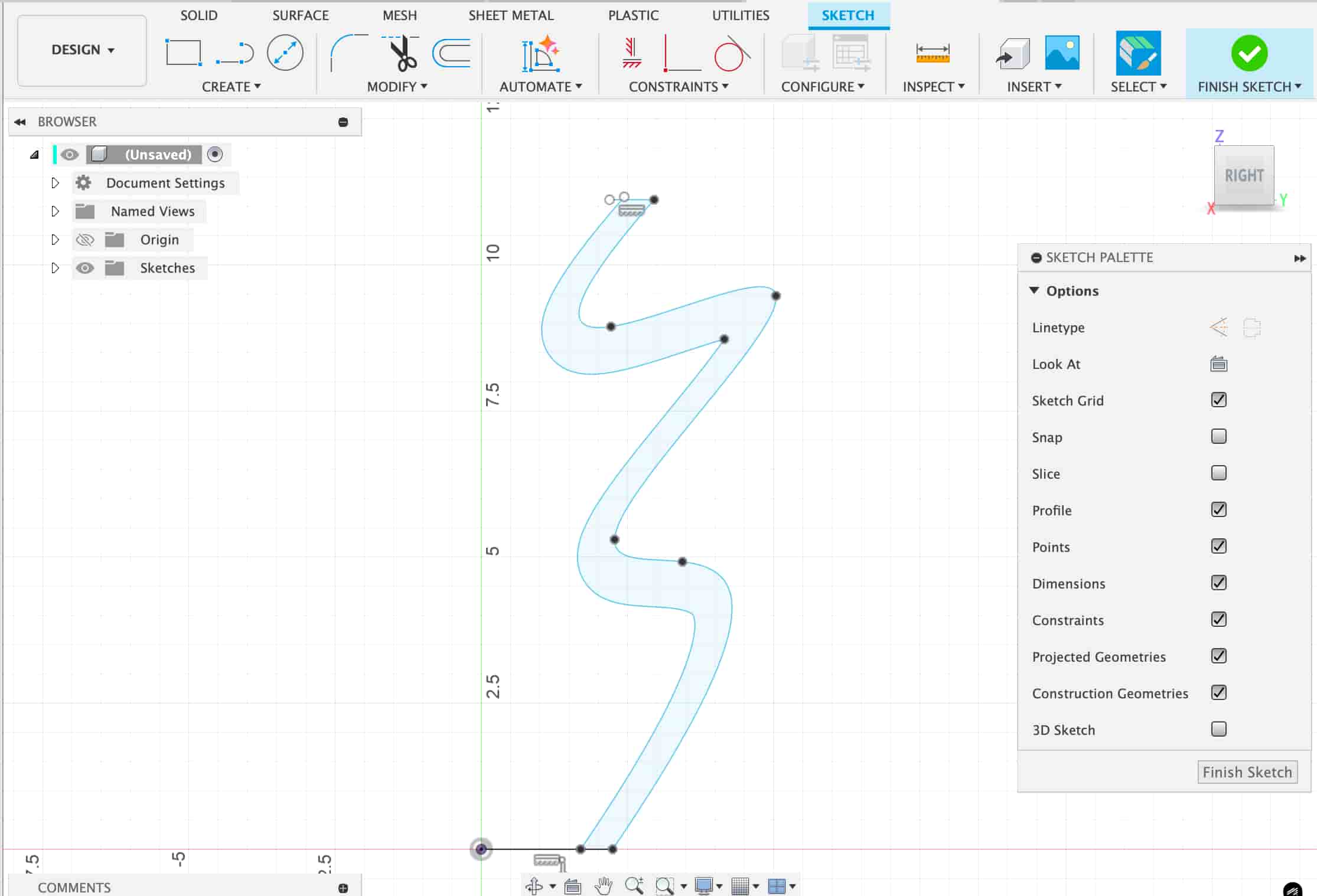
2.1 Base Profile Sketch
Draw a smooth, flowing profile on a vertical plane to define the vase’s outer shape.
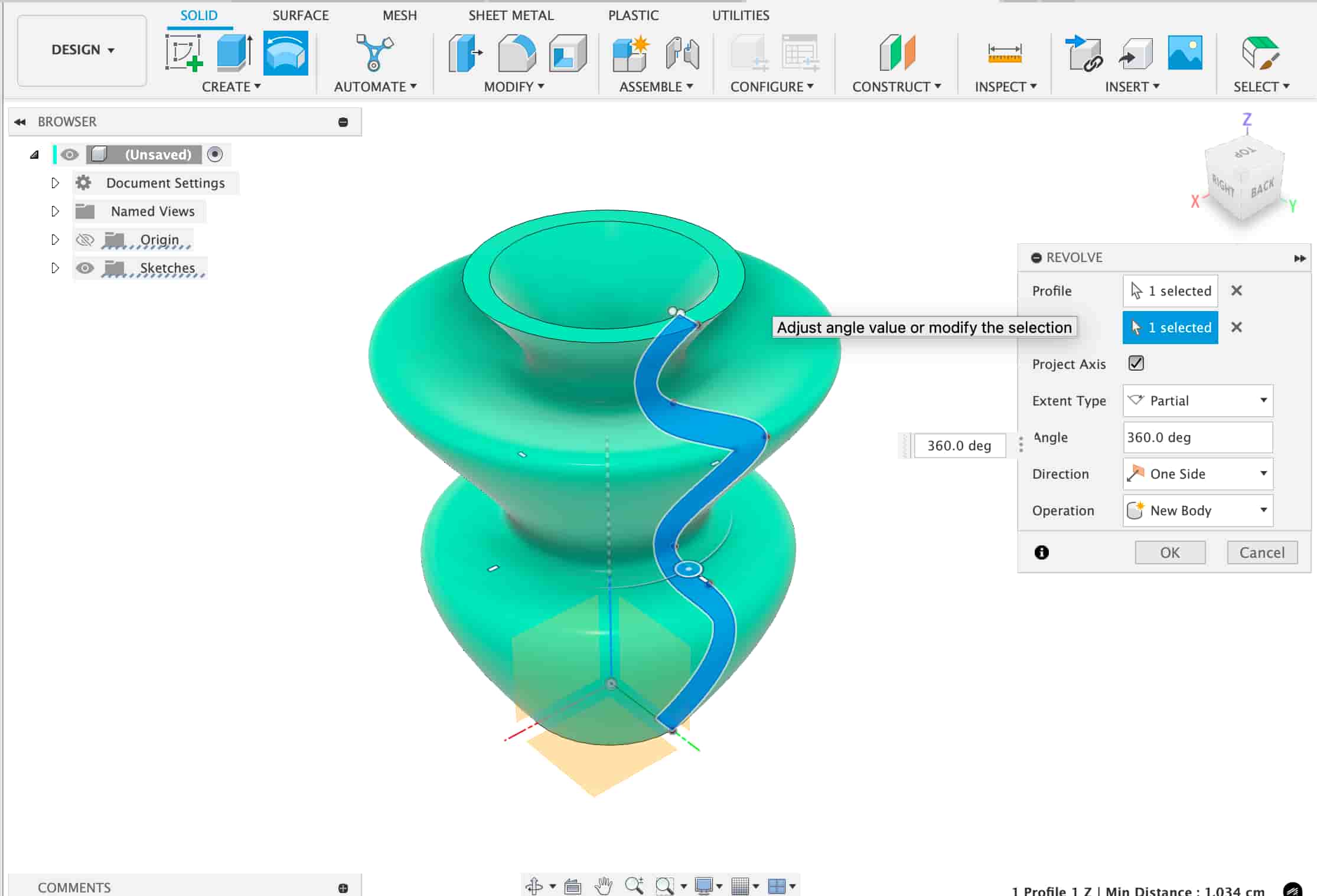
2.2 Revolve Operation
Revolve the sketch 360° around the central axis to generate the base vase body.
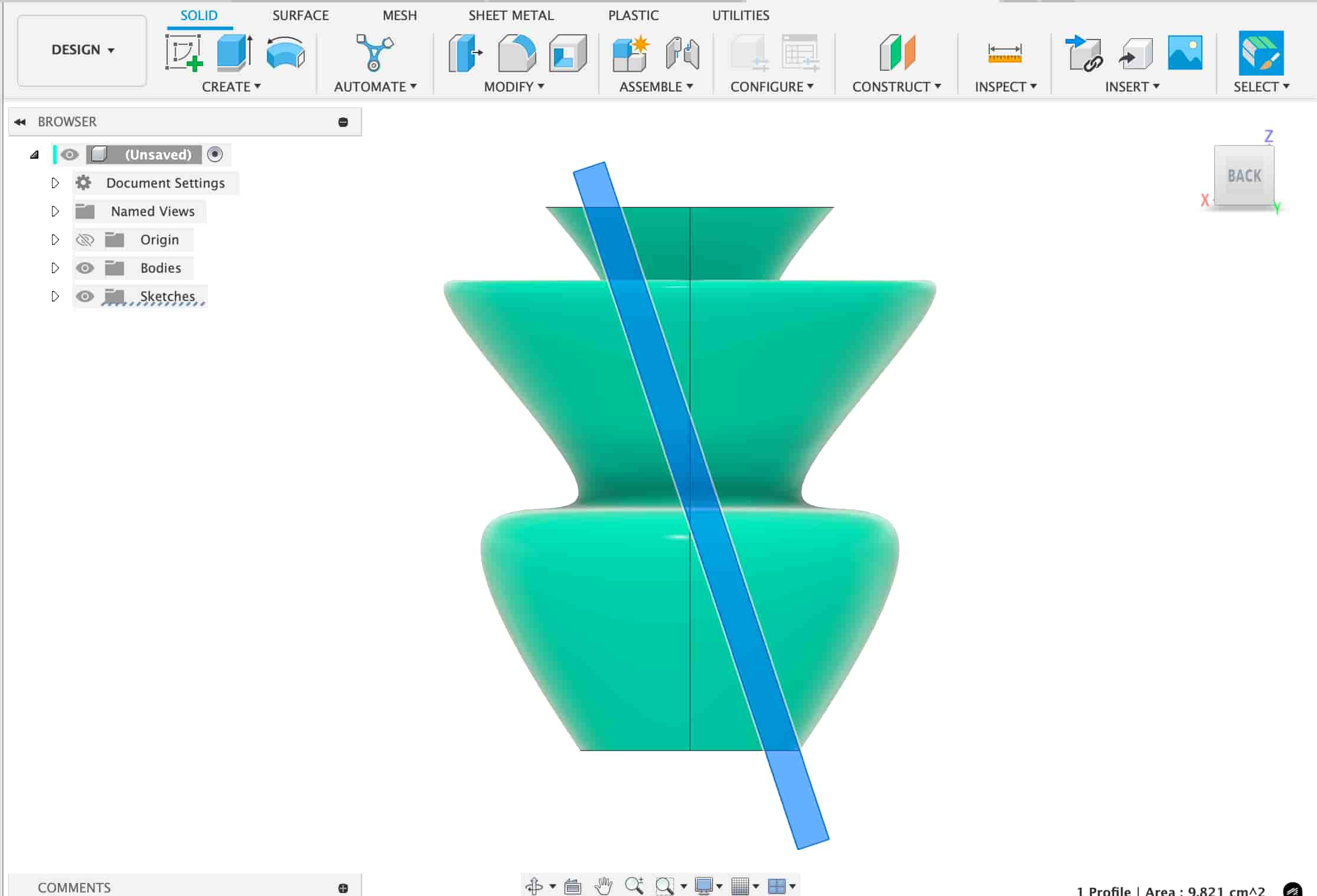
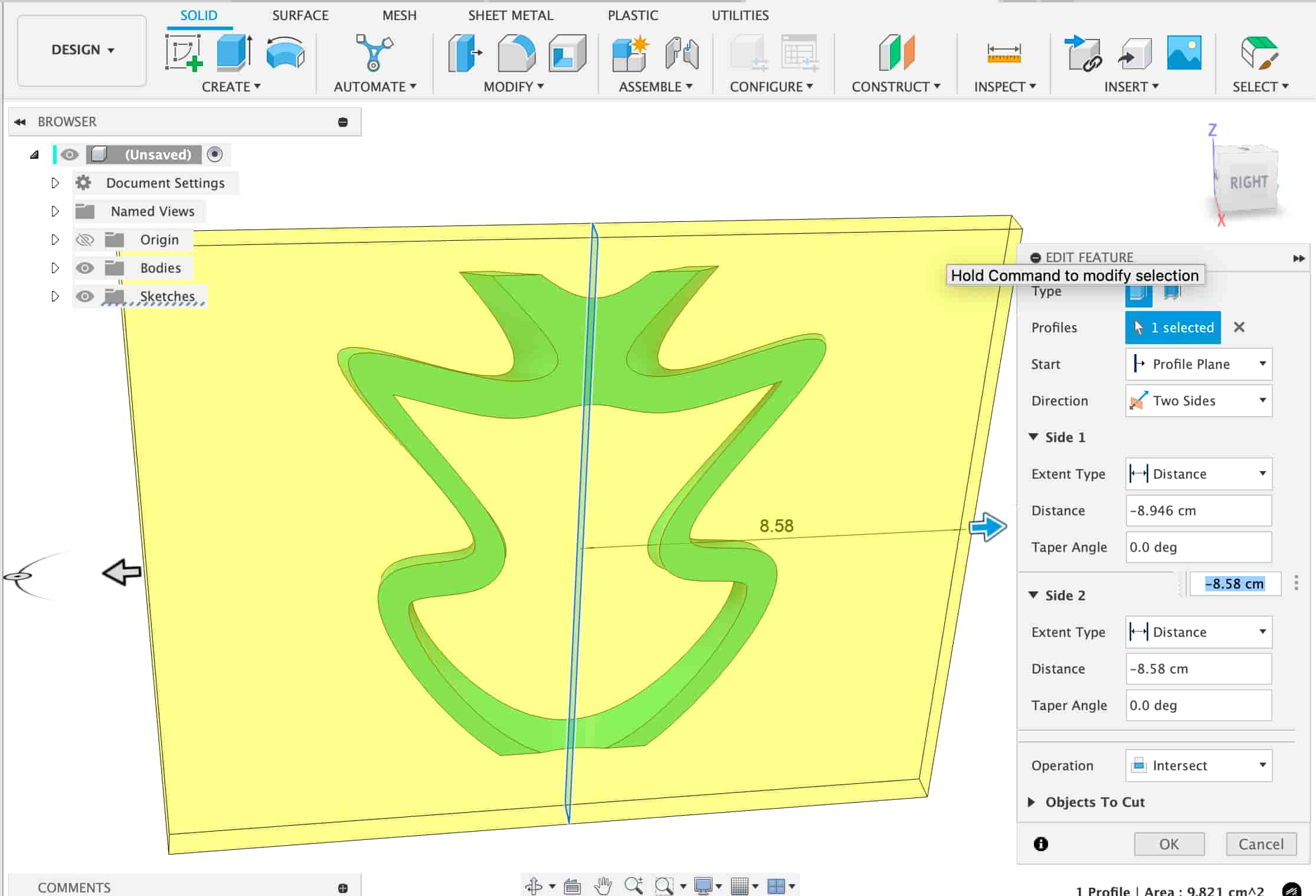
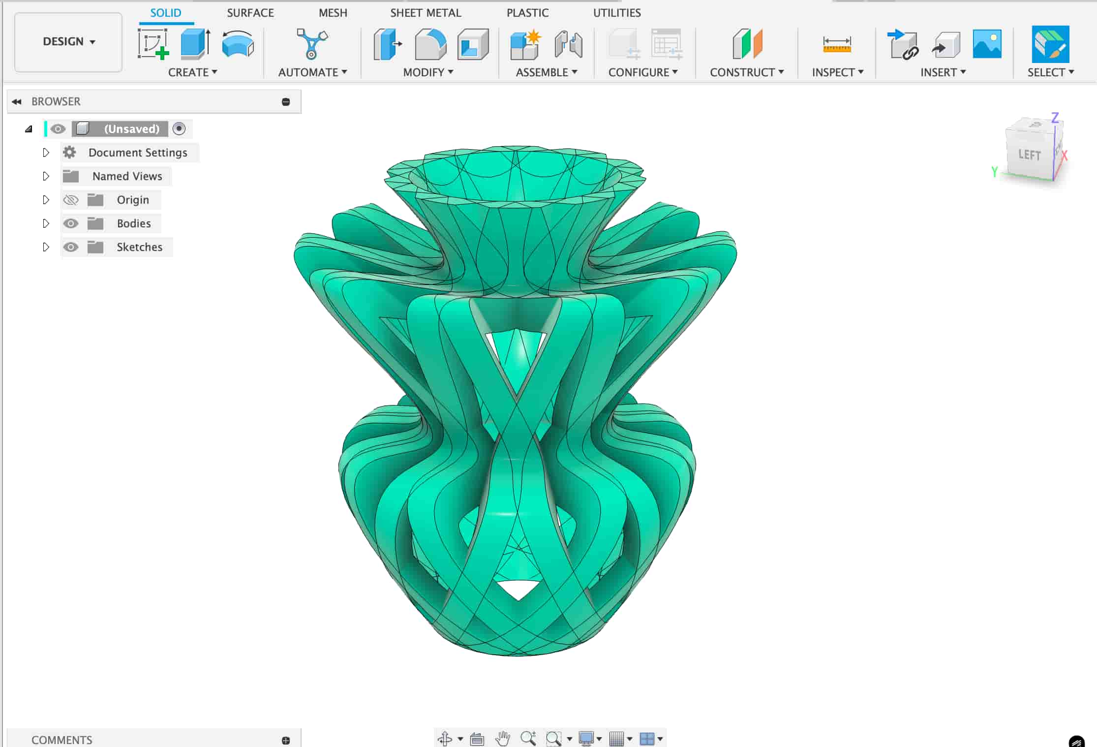
2.3 Cutout Sketch & Intersect
Create a wavy cutout sketch and perform an Intersect with the main body to produce enclosed internal cavities.
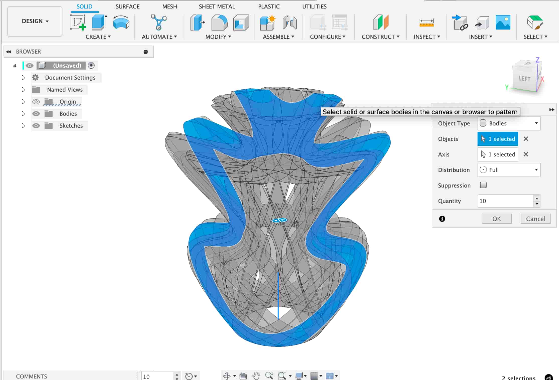
2.4 Circular Pattern
Use the Circular Pattern tool to replicate the cutout feature ten times around the axis, creating a uniform radial design.
3. 3D Printing Setup (Bambu Studio)
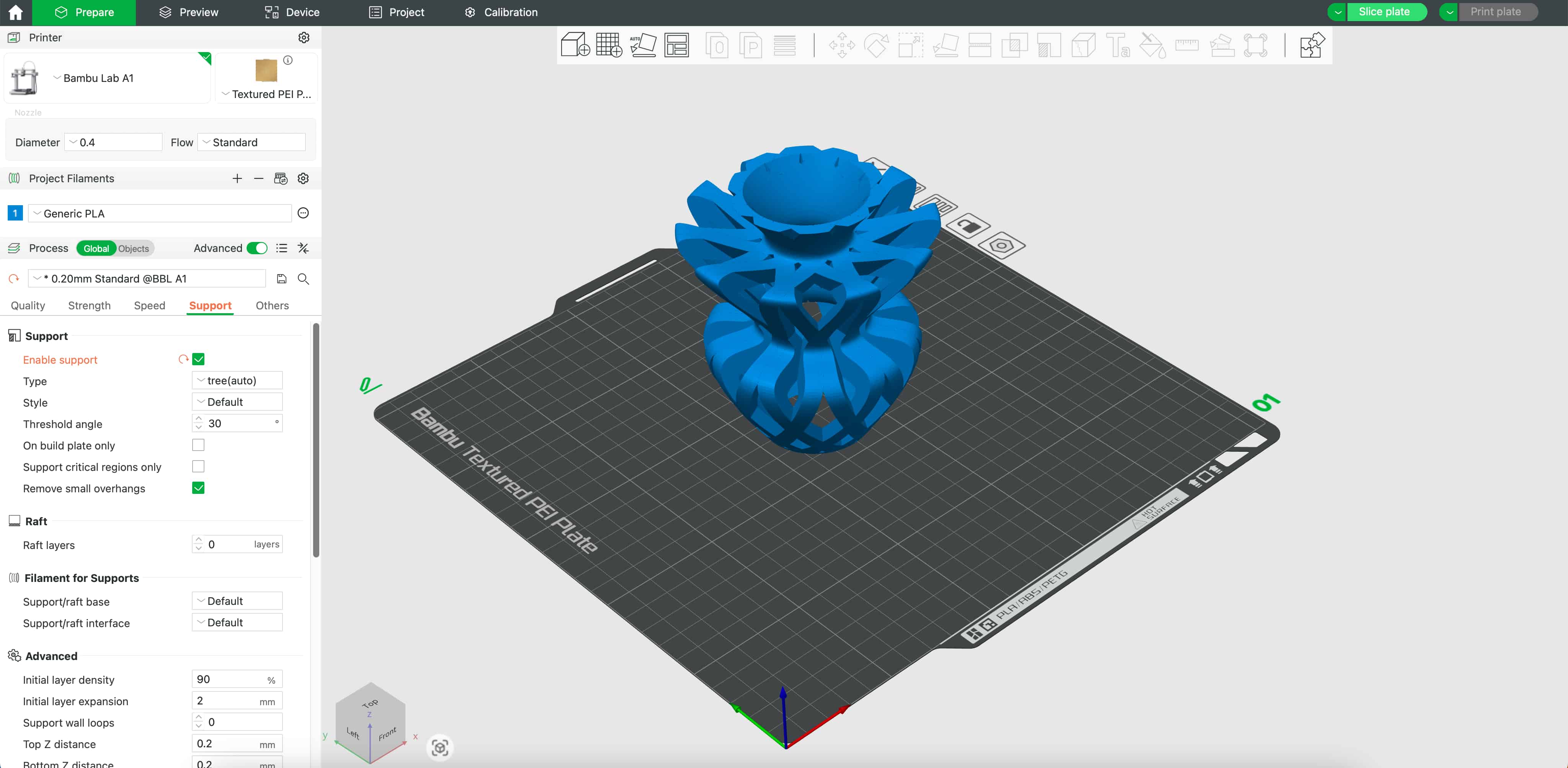
Setting Value Printer Bambu Lab A1 Filament Generic PLA Layer Height 0.20 mm Nozzle Size 0.40 mm Support Type Tree (Auto) Support Threshold Angle 30° Remove Small Overhangs Enabled
Preview of support settings and plate layout:
Slicing preview (model in orange, supports in green):
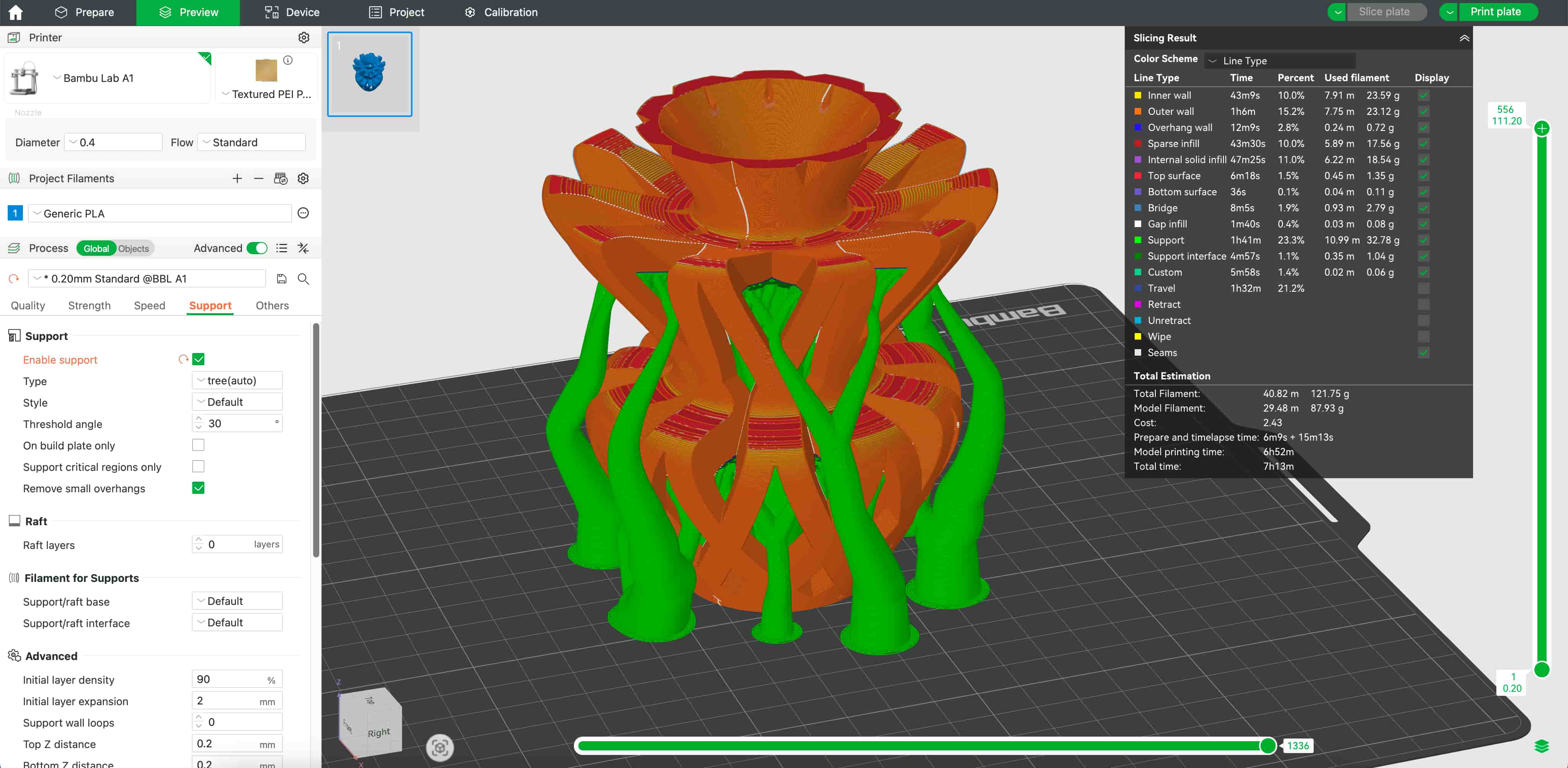
Slicing Results:
Metric Time Filament Model Print Time 6h 52m 87.93 g Total Job Time 7h 13m 121.75 g Support Material 1h 41m 32.78 g
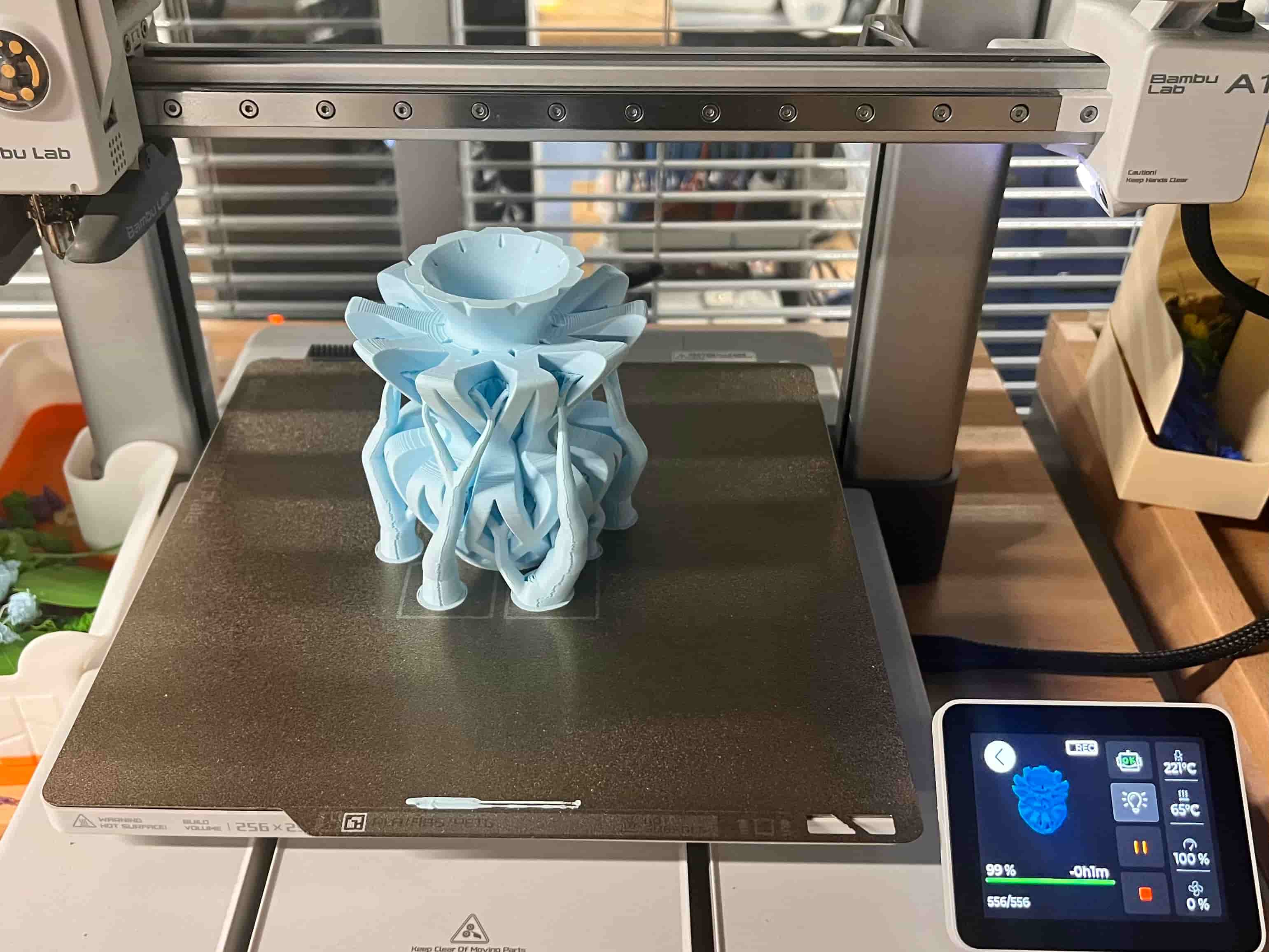
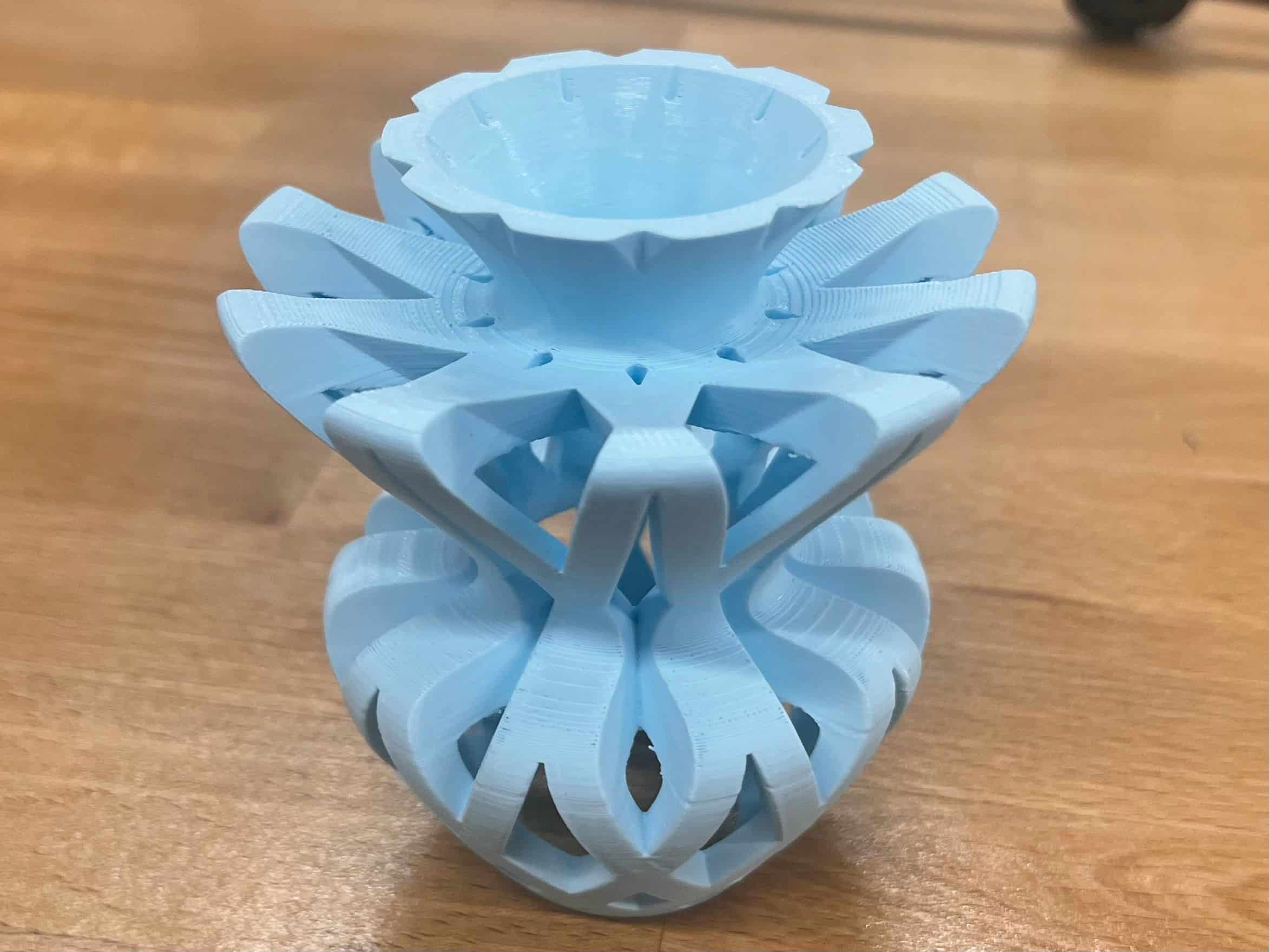
Print Results:
Download Design Files
I exported the file in f3z format. Here is the zip
4. Key Takeaways
- Revolve + Intersect: Effective combination for creating fully enclosed internal voids.
- Circular Pattern: Fast method to achieve consistent radial symmetry.
- Tree Supports: Optimize filament usage while handling steep overhangs.
- High-Resolution Mesh: Exporting a fine STL improves surface quality.
5. Future Development Suggestions
- Experiment with dual-color printing or advanced post-processing for enhanced aesthetics.
- Manually refine support contact points and perform light sanding after printing.
- Test alternative materials (PETG, TPU) for strength and flexibility comparisons.
6. Why Only Manufacturable by 3D Printing?
6.1 Closed Internal Cavities & Undercuts
The intersected cutouts form completely enclosed voids. No CNC tool or drill can access and carve these internal features.
6.2 Complex Overhangs & Support Requirements
The organic “petal” elements sit at steep angles and twist around the body. Injection molds would require intricate side-actions, and multi-axis milling would collide with surrounding geometry.
6.3 Radial Symmetry & Tolerance
Replicating ten identical features around the axis demands precise indexing or multiple fixtures, which is impractical with traditional tooling.
6.4 One-Piece Integrity
The vase is designed as a single, seamless shell. Splitting into sub-parts introduces seams, bonding steps, and disrupts the organic flow.
6.5 Organic Parametric Form
Subtractive methods either over-mill or leave faceted edges on these smooth, variable-thickness curves, whereas layer-by-layer printing reproduces them faithfully.
In summary, additive manufacturing (3D printing) is uniquely capable of:
- Supporting steep overhangs with tree-style supports
- Creating fully enclosed internal geometries in a single build
- Producing seamless, one-piece organic forms without assembly
- Maintaining consistent detail across all radial repeats
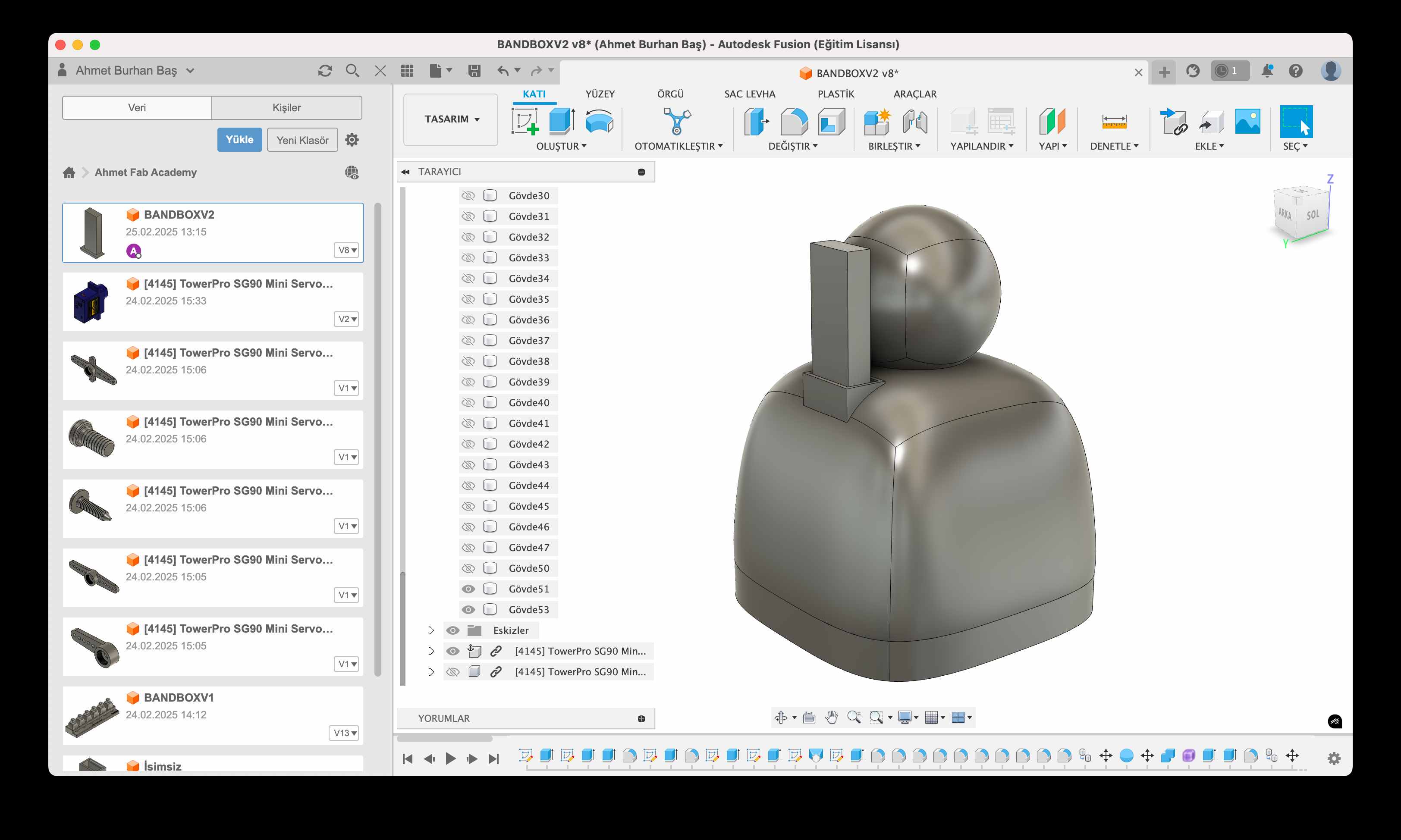
Designing in Fusion360
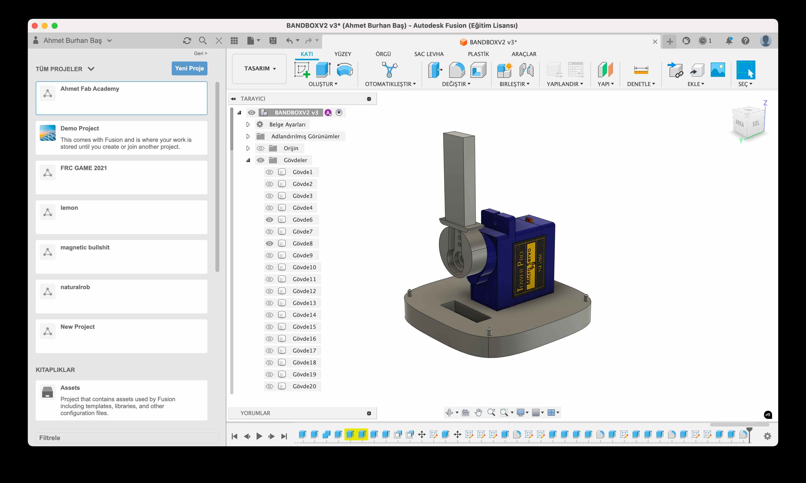
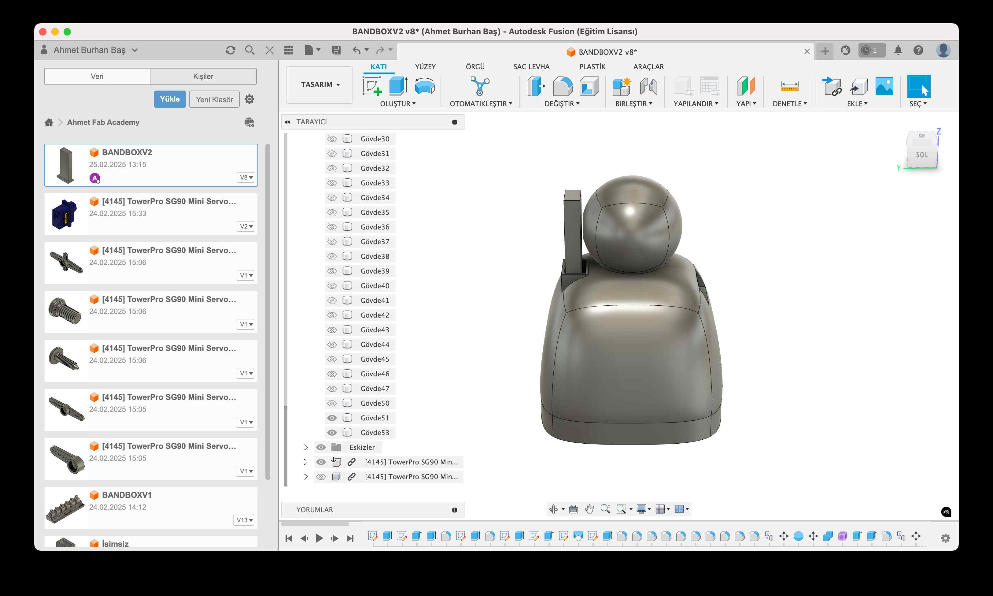
I started by designing a sample model for my final project. The design uses an SG90 Servo Motor to power a cam mechanism, which makes the figure move its arm up and down.
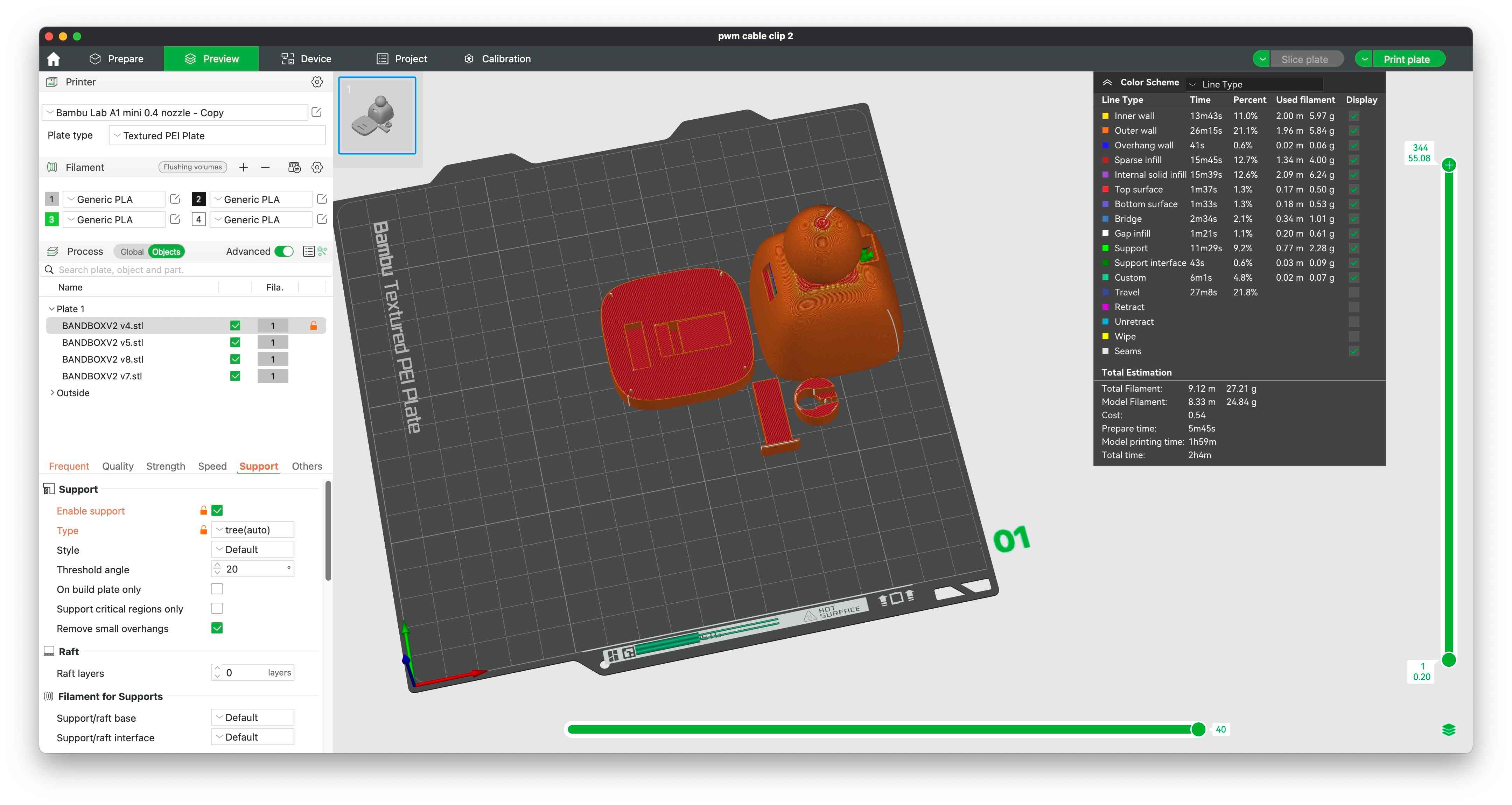
Then I exported all the parts separately from Fusion360 and used Bambu Studio to slice the files.
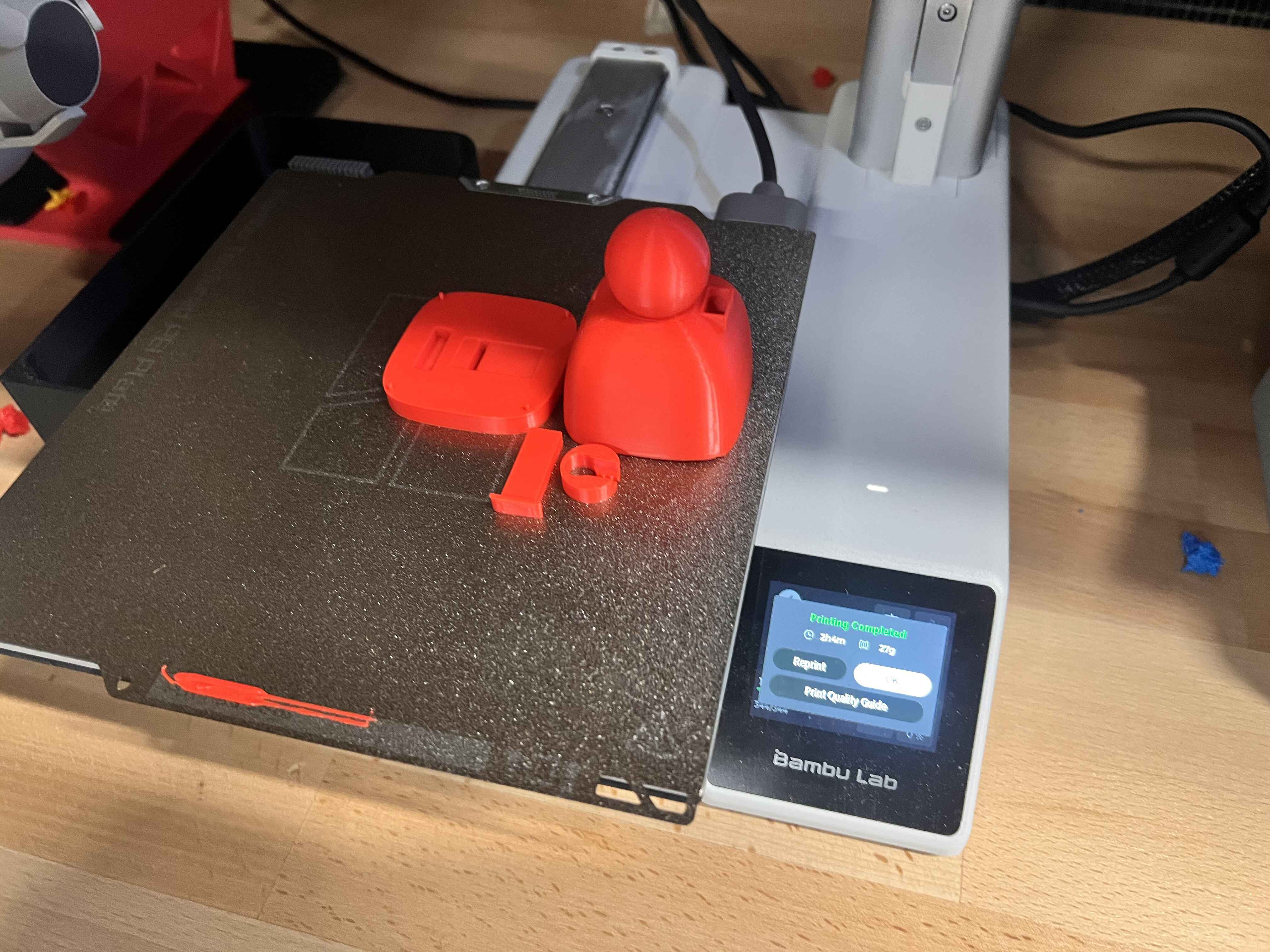
I used a Bambu Lab A1 Mini printer to print the parts. Here is the finished print:
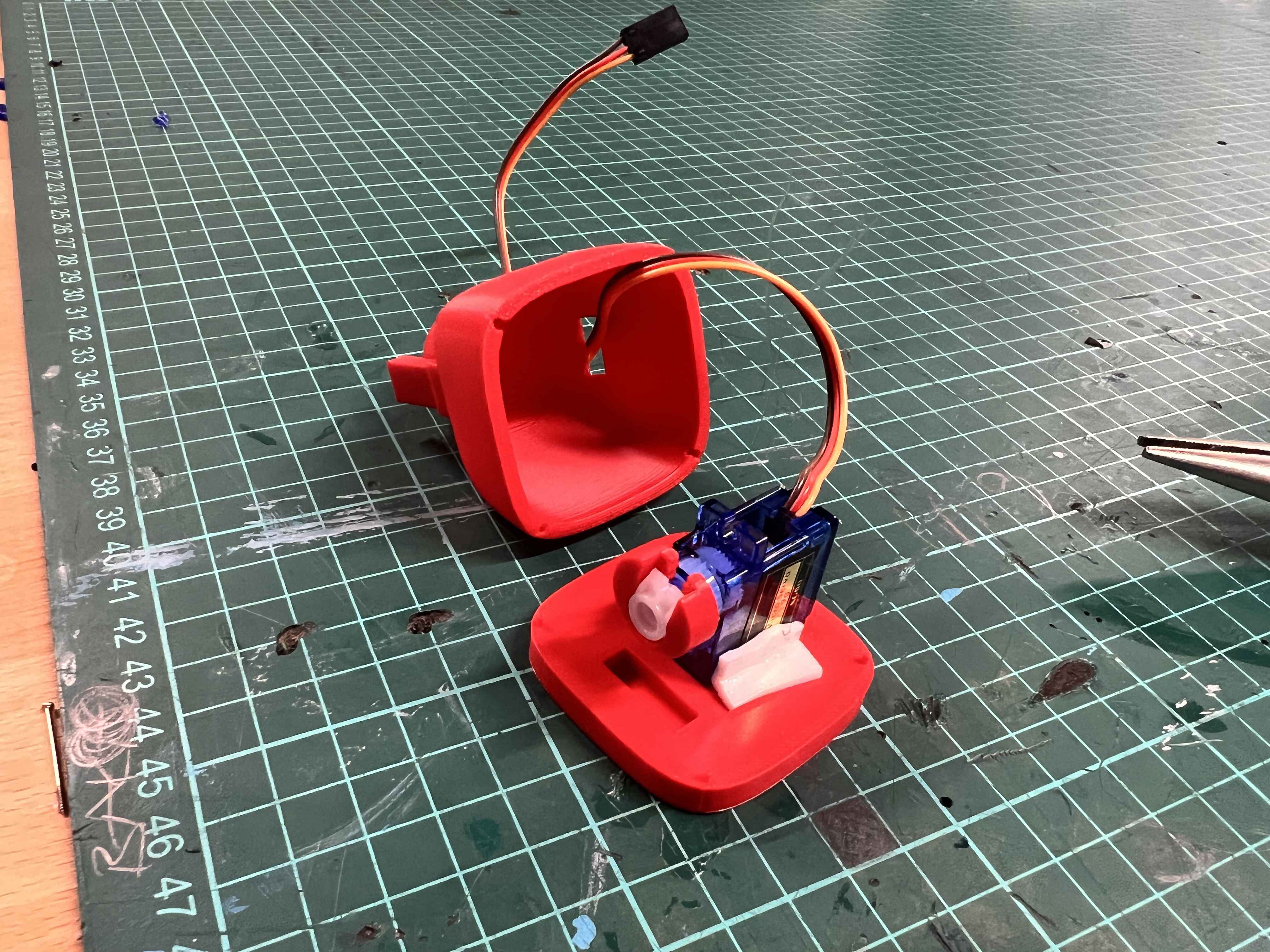
Assembly of the Figure
I assembled all the parts and just used tape to secure the servo in place since this is just a prototype.
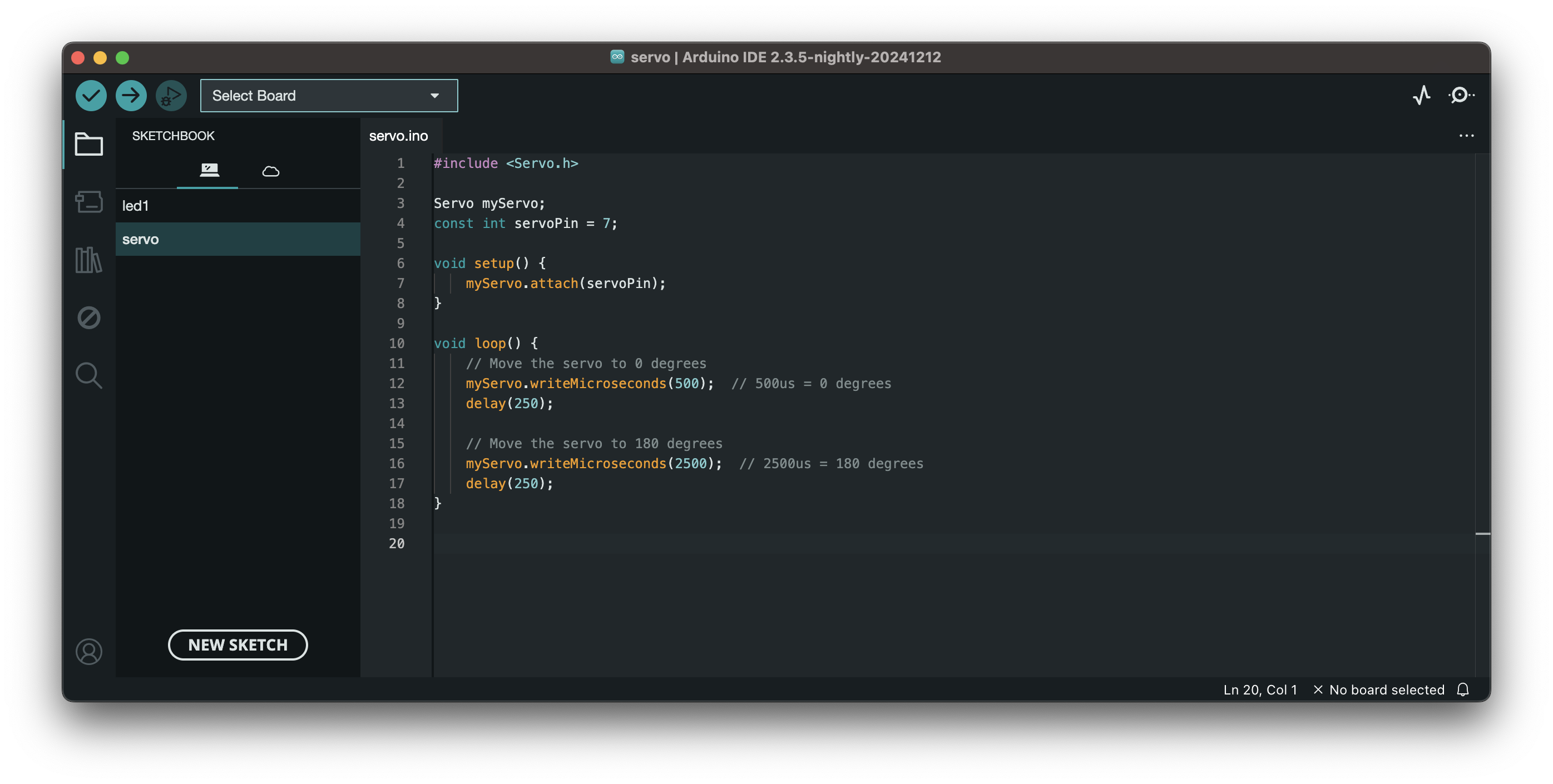
As the last step, I connected the Servo to a Pi Pico and ran this code in Arduino IDE:
Here is a video of the final product:
Download Design Files
I exported the file in f3z format. Here is the zip
Scanning
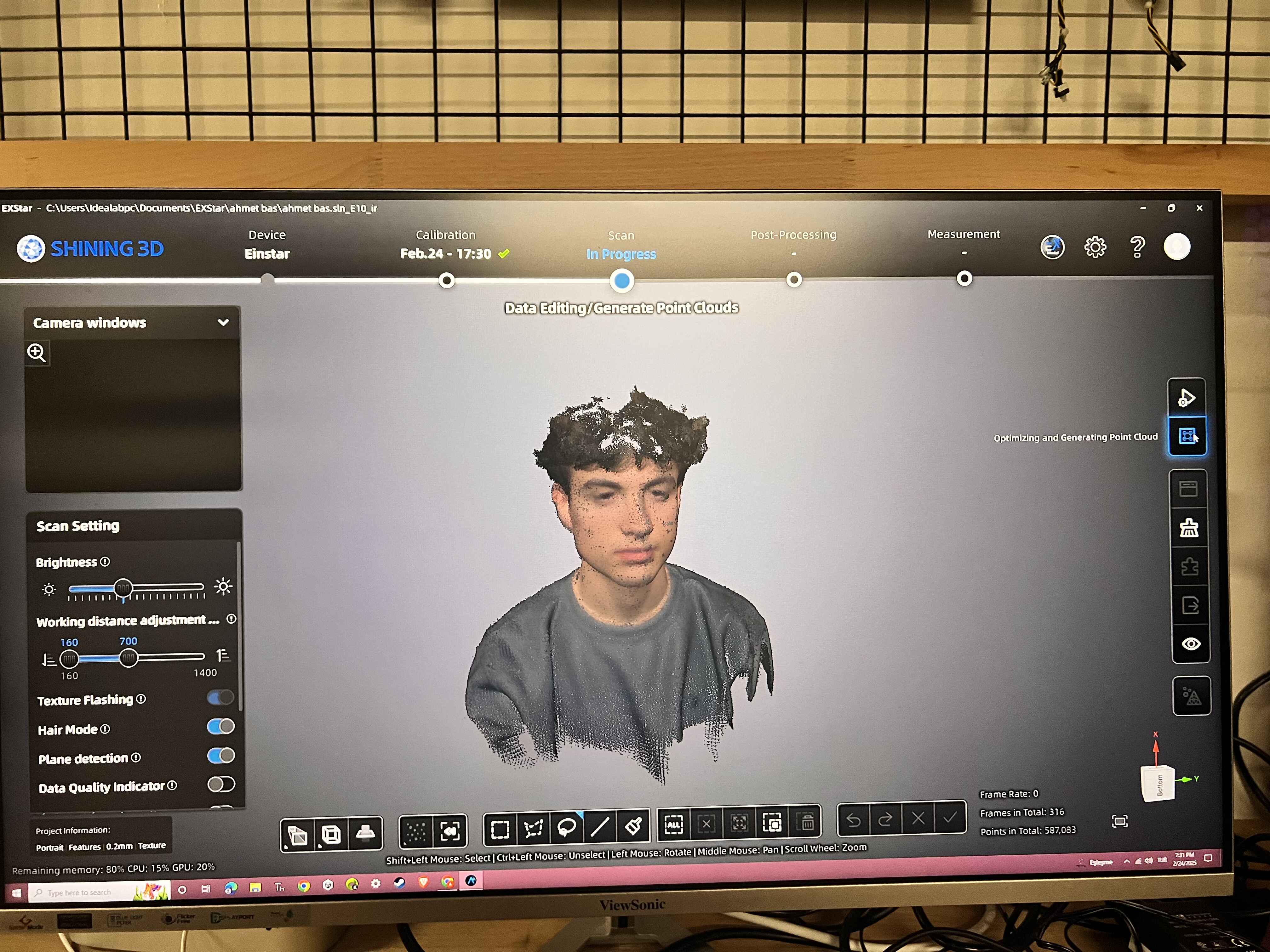
I used the Shining 3D Einstar 3D scanner along with the EXStar software.
I began by calibrating the scanner using the included white calibration board. Following the software’s instructions, I scanned the board from various angles to complete the process.
To start a new project, I followed these steps:
- New Project
- Scan Mode: Portrait
- Object Size: Medium & Large Objects
- Alignment Mode: Texture Alignment
- Resolution: 0.2
- Texture Scan: Enabled
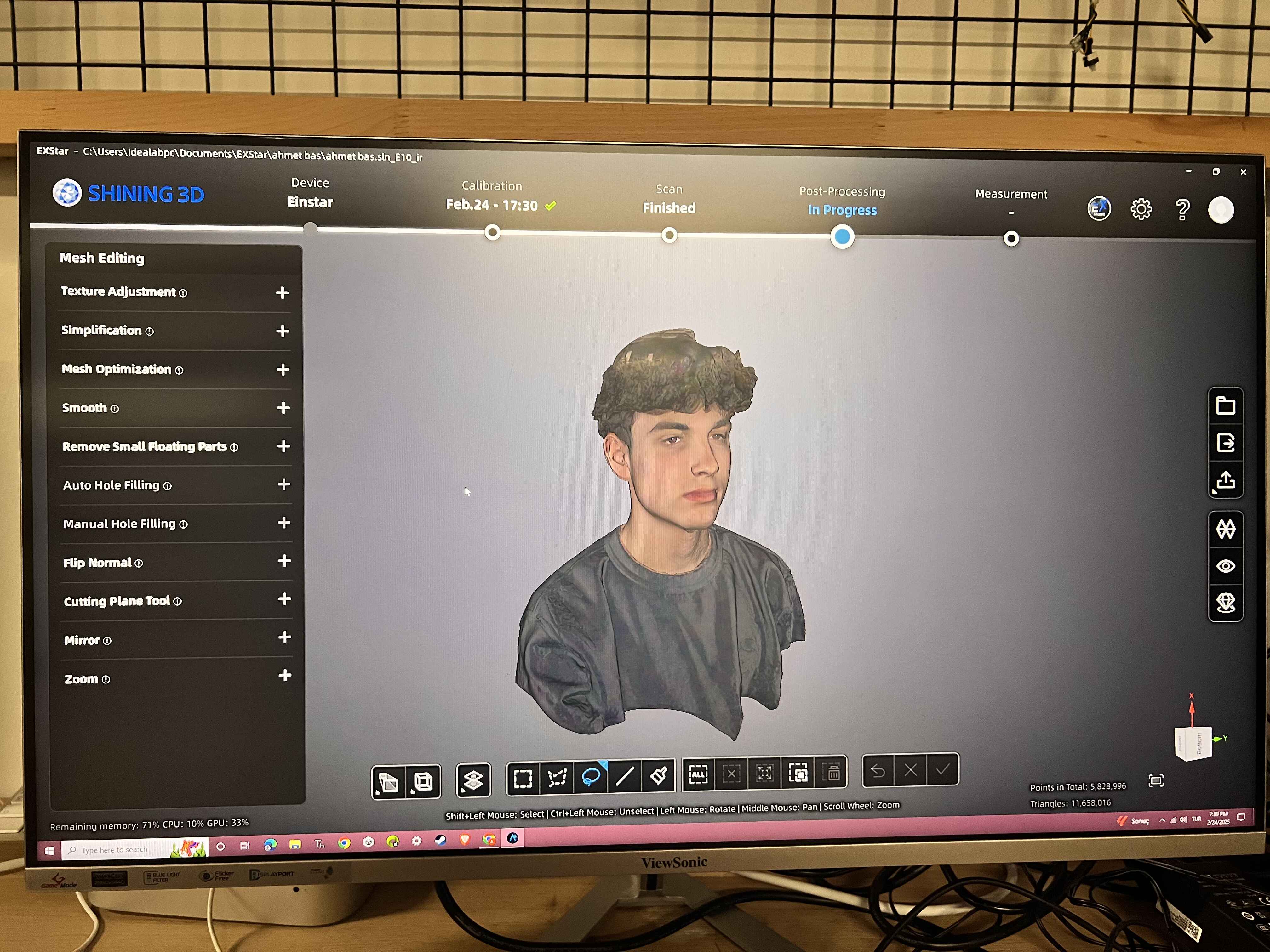
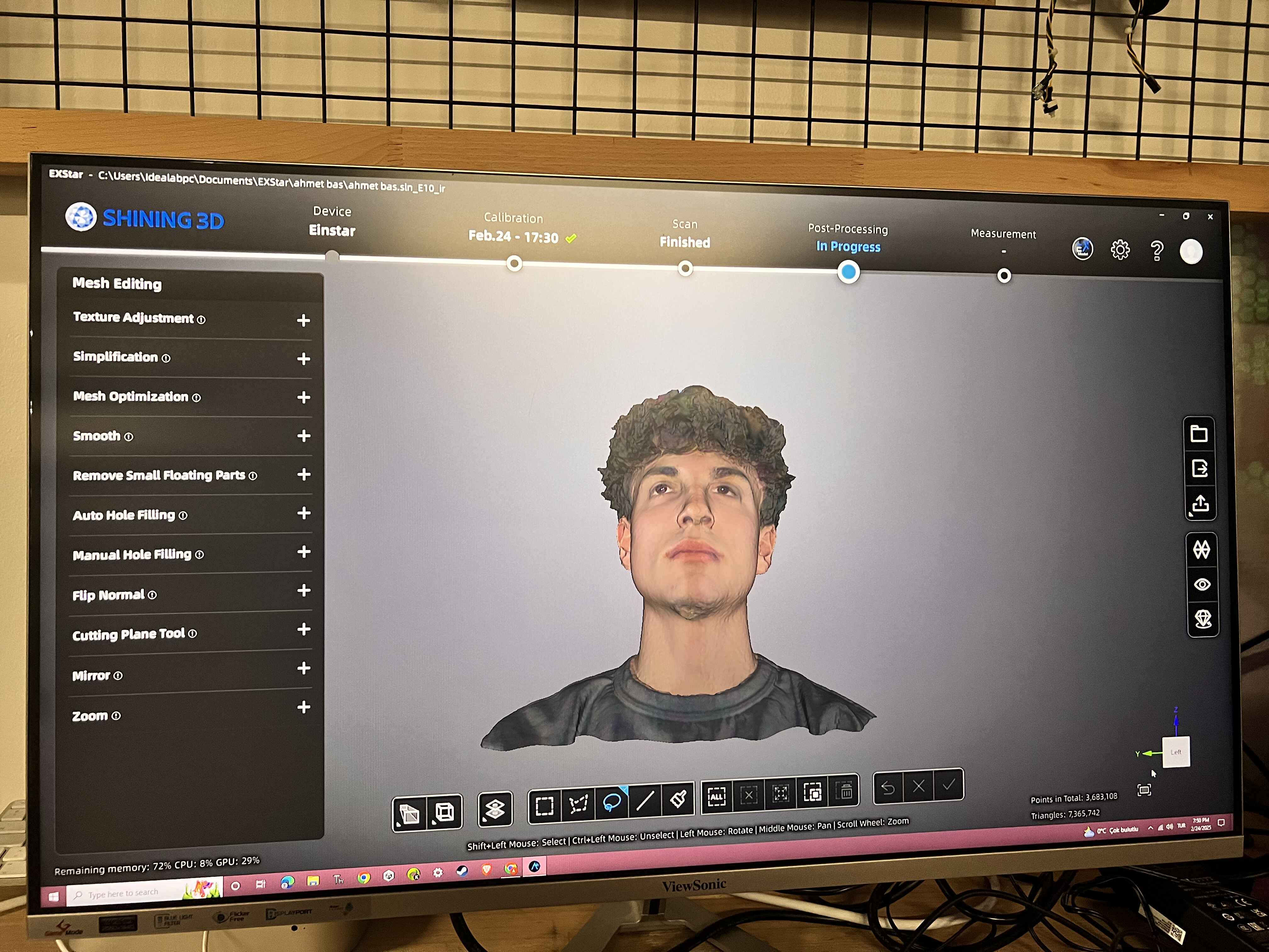
After capturing the scan, I selected Mesh Model to generate a more solid object. Below are images showcasing different stages of the process.
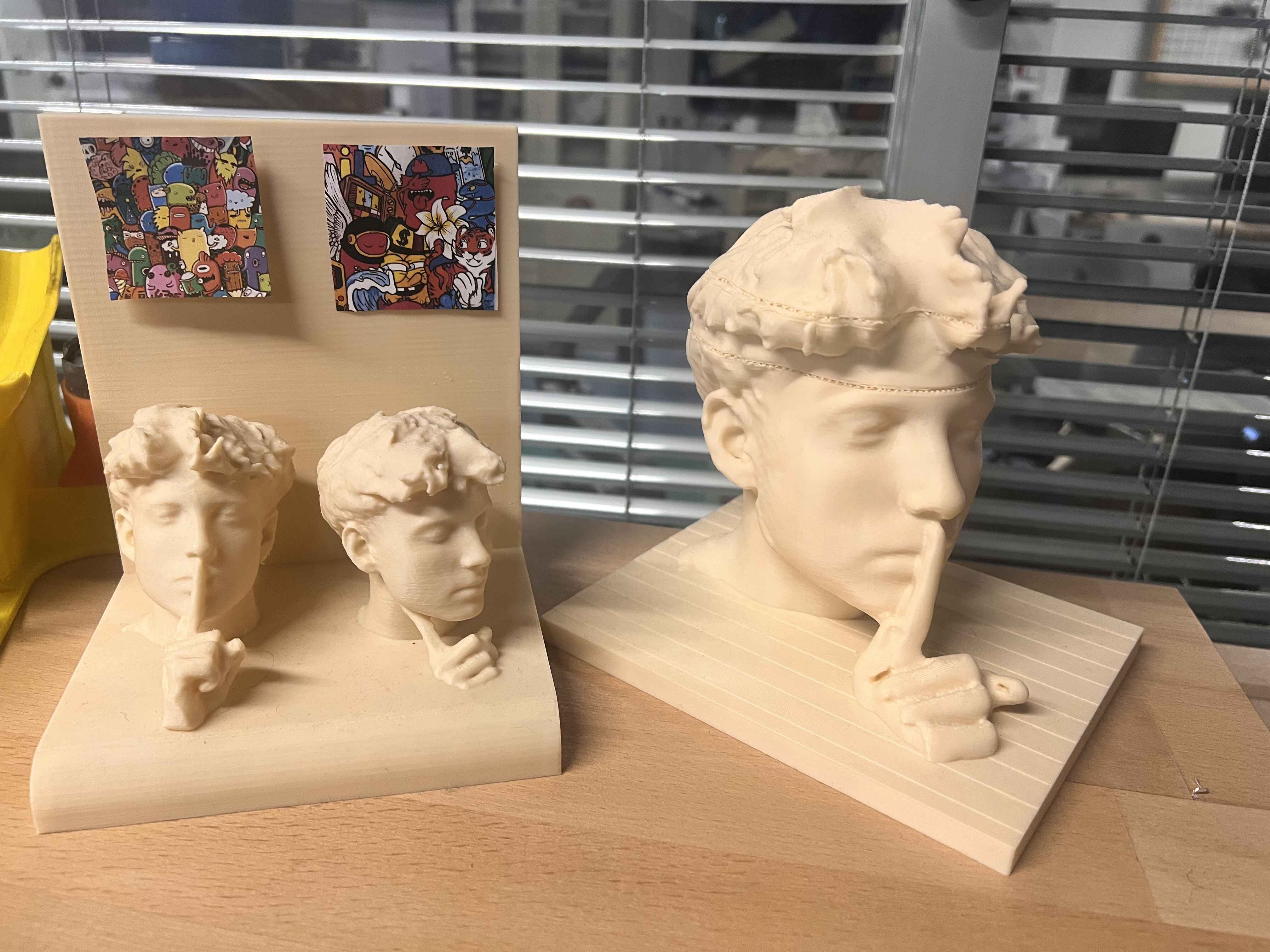
I had already done this in the past just for fun, so I had some 3D printed scans of my head laying around :)
1. Project Overview
This project covers the creation of an organic, Voronoi-inspired vase form using Fusion 360’s parametric sketch and modeling tools, followed by printing on a Bambu Lab A1 with PLA filament.
2. Fusion 360 Design Steps
2.1 Base Profile Sketch
Draw a smooth, flowing profile on a vertical plane to define the vase’s outer shape.
2.2 Revolve Operation
Revolve the sketch 360° around the central axis to generate the base vase body.
2.3 Cutout Sketch & Intersect
Create a wavy cutout sketch and perform an Intersect with the main body to produce enclosed internal cavities.
2.4 Circular Pattern
Use the Circular Pattern tool to replicate the cutout feature ten times around the axis, creating a uniform radial design.
3. 3D Printing Setup (Bambu Studio)
| Setting | Value |
|---|---|
| Printer | Bambu Lab A1 |
| Filament | Generic PLA |
| Layer Height | 0.20 mm |
| Nozzle Size | 0.40 mm |
| Support Type | Tree (Auto) |
| Support Threshold Angle | 30° |
| Remove Small Overhangs | Enabled |
Preview of support settings and plate layout:
Slicing preview (model in orange, supports in green):
Slicing Results:
| Metric | Time | Filament |
|---|---|---|
| Model Print Time | 6h 52m | 87.93 g |
| Total Job Time | 7h 13m | 121.75 g |
| Support Material | 1h 41m | 32.78 g |
Print Results:
Download Design Files
I exported the file in f3z format. Here is the zip
4. Key Takeaways
- Revolve + Intersect: Effective combination for creating fully enclosed internal voids.
- Circular Pattern: Fast method to achieve consistent radial symmetry.
- Tree Supports: Optimize filament usage while handling steep overhangs.
- High-Resolution Mesh: Exporting a fine STL improves surface quality.
5. Future Development Suggestions
- Experiment with dual-color printing or advanced post-processing for enhanced aesthetics.
- Manually refine support contact points and perform light sanding after printing.
- Test alternative materials (PETG, TPU) for strength and flexibility comparisons.
6. Why Only Manufacturable by 3D Printing?
6.1 Closed Internal Cavities & Undercuts
The intersected cutouts form completely enclosed voids. No CNC tool or drill can access and carve these internal features.
6.2 Complex Overhangs & Support Requirements
The organic “petal” elements sit at steep angles and twist around the body. Injection molds would require intricate side-actions, and multi-axis milling would collide with surrounding geometry.
6.3 Radial Symmetry & Tolerance
Replicating ten identical features around the axis demands precise indexing or multiple fixtures, which is impractical with traditional tooling.
6.4 One-Piece Integrity
The vase is designed as a single, seamless shell. Splitting into sub-parts introduces seams, bonding steps, and disrupts the organic flow.
6.5 Organic Parametric Form
Subtractive methods either over-mill or leave faceted edges on these smooth, variable-thickness curves, whereas layer-by-layer printing reproduces them faithfully.
In summary, additive manufacturing (3D printing) is uniquely capable of:
- Supporting steep overhangs with tree-style supports
- Creating fully enclosed internal geometries in a single build
- Producing seamless, one-piece organic forms without assembly
- Maintaining consistent detail across all radial repeats
Designing in Fusion360
I started by designing a sample model for my final project. The design uses an SG90 Servo Motor to power a cam mechanism, which makes the figure move its arm up and down.
Then I exported all the parts separately from Fusion360 and used Bambu Studio to slice the files.
I used a Bambu Lab A1 Mini printer to print the parts. Here is the finished print:
Assembly of the Figure
I assembled all the parts and just used tape to secure the servo in place since this is just a prototype.
As the last step, I connected the Servo to a Pi Pico and ran this code in Arduino IDE:
Here is a video of the final product:
Download Design Files
I exported the file in f3z format. Here is the zip
Scanning
I used the Shining 3D Einstar 3D scanner along with the EXStar software.
I began by calibrating the scanner using the included white calibration board. Following the software’s instructions, I scanned the board from various angles to complete the process.
To start a new project, I followed these steps:
- New Project
- Scan Mode: Portrait
- Object Size: Medium & Large Objects
- Alignment Mode: Texture Alignment
- Resolution: 0.2
- Texture Scan: Enabled
After capturing the scan, I selected Mesh Model to generate a more solid object. Below are images showcasing different stages of the process.
I had already done this in the past just for fun, so I had some 3D printed scans of my head laying around :)