4. Embedded Programming
Group Assignment
Click to access the group assignment
Information about Raspberry Pi Pico
The Raspberry Pi Pico is a small, cheap, and powerful board based on the RP2040 microcontroller chip. It’s made for hobby projects and embedded programming.
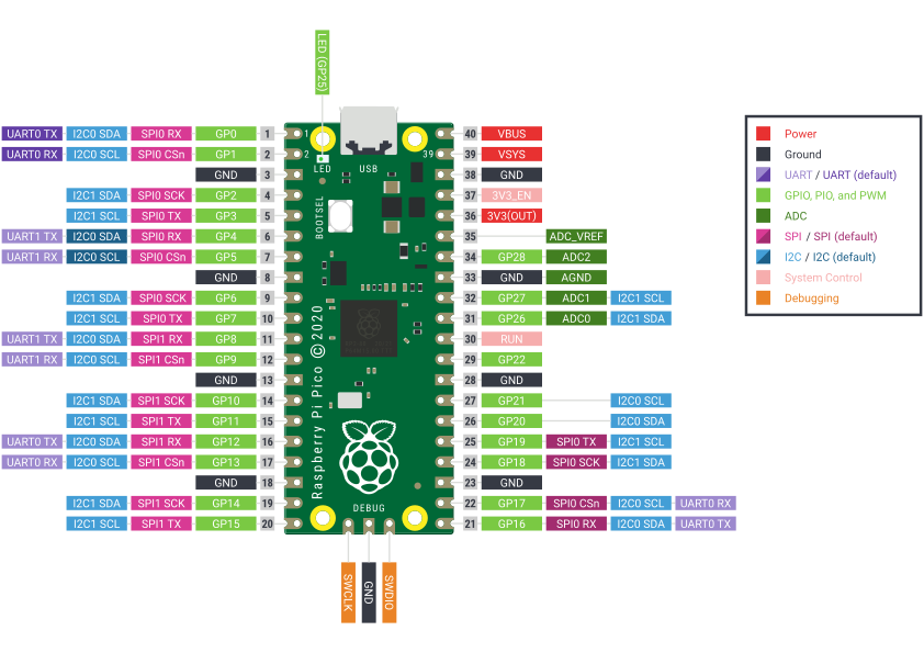
- 2-core processor running at up to 133 MHz
- 26 GPIO pins (some support ADC)
- Supports USB power and data connection
- Works with MicroPython or C/C++
- Programmable I/O can emulate VGA, SD cards, etc.
- Comes with deep sleep and dormant power modes
Some Random Fun Facts
- You reprogram it by holding a button and dragging a file — like magic.
- It only costs $4–5!
- The BOOTSEL button is used to enter mass storage mode.
- There’s a built-in LED connected to pin 25.
- It can run in temperatures from -20°C to 85°C.
- “Popcorn mode” is an actual power demo in the docs.
4-LED Sequential Blinking Project with Raspberry Pi Pico
1. Started with Wokwi Simulator and Raspberry Pi Pico
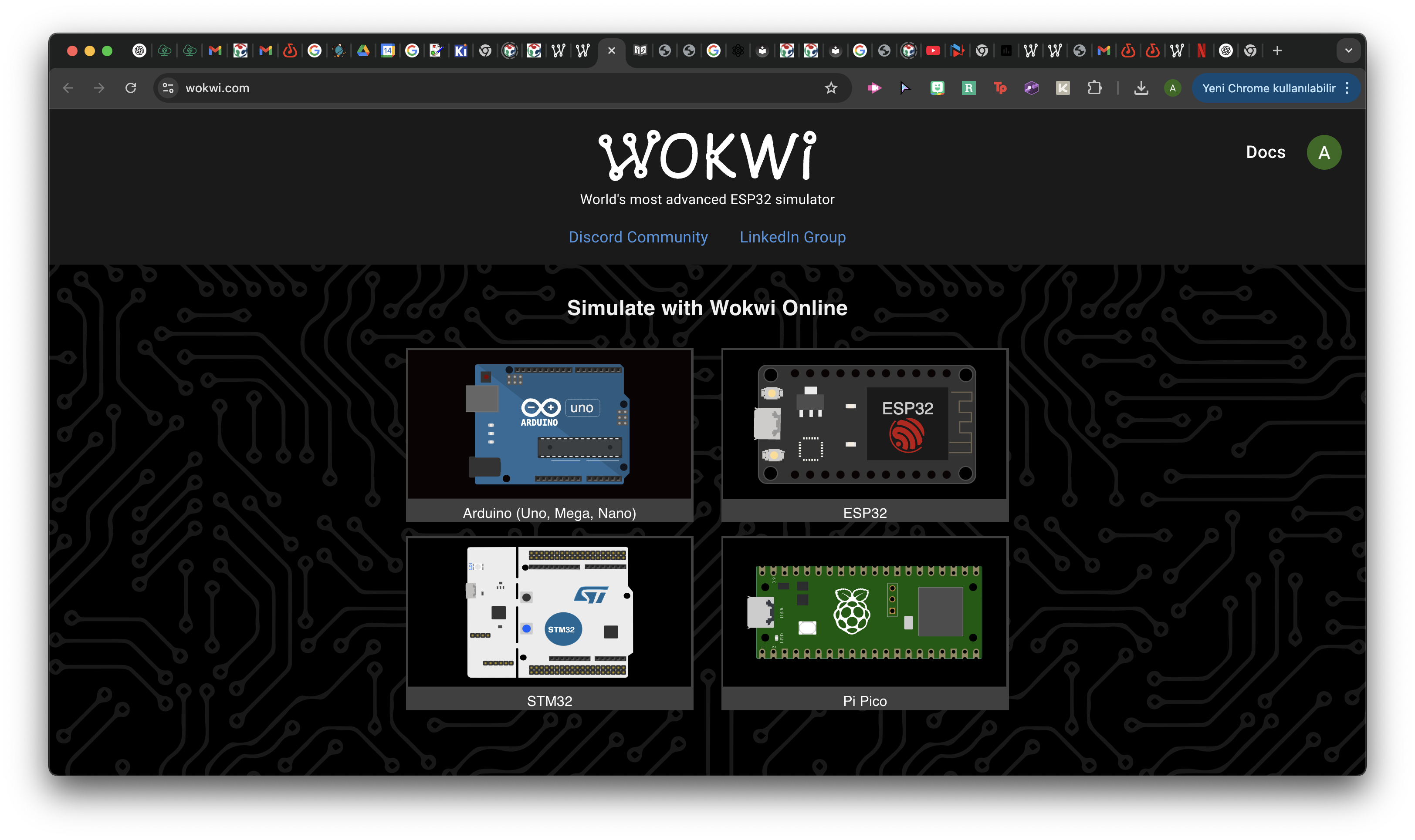
I began the project by opening Wokwi.com and selecting the Raspberry Pi Pico board from the main simulation options. Wokwi allows you to simulate microcontroller projects without needing real hardware.
2. Modified the Traffic Light Setup to 4 Blue LEDs
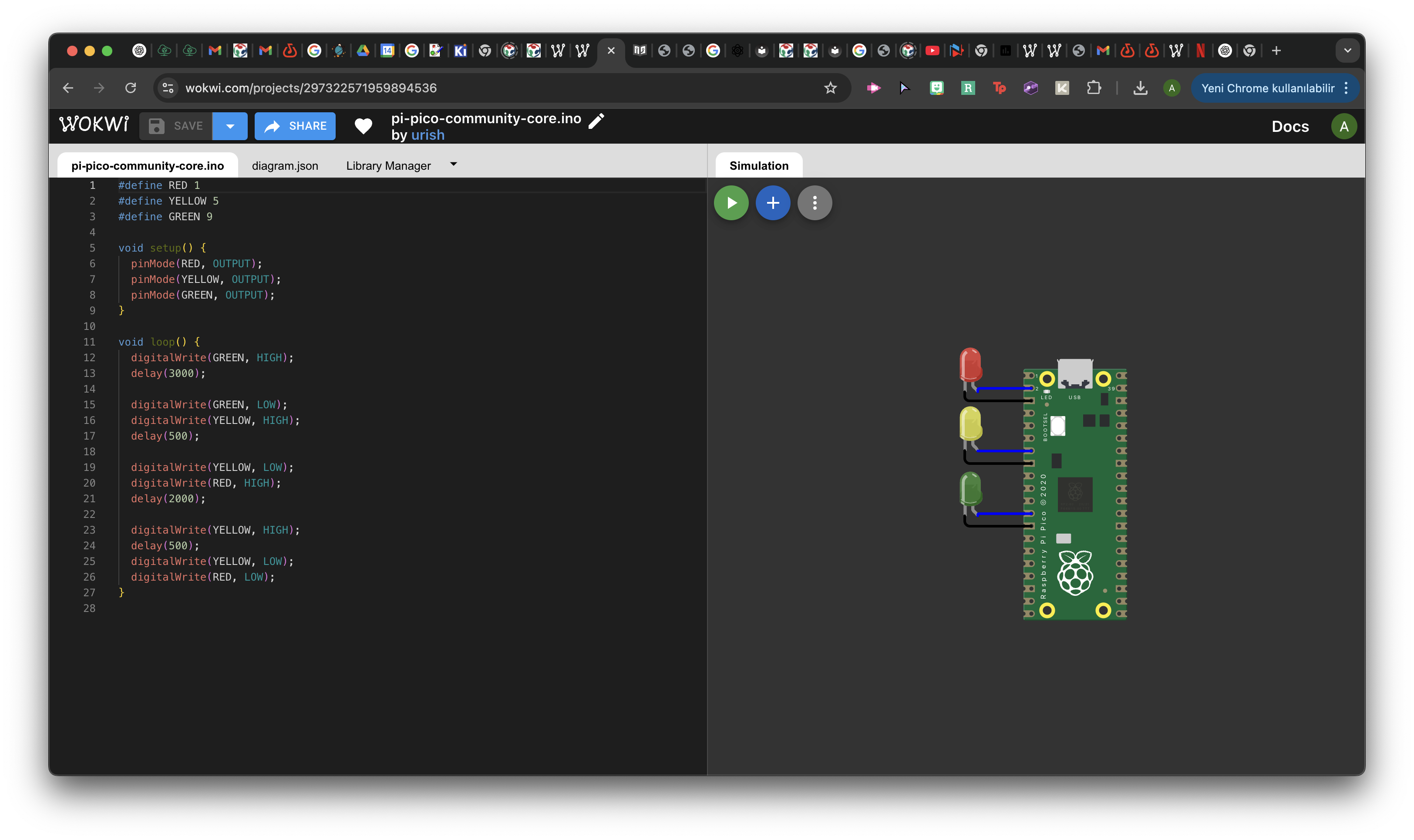
The original simulation was a basic traffic light circuit using red, yellow, and green LEDs. I used it as a base.
I modified this project to use 4 blue LEDs, each connected to a different GPIO pin on the Raspberry Pi Pico. This created a sequential blinking pattern instead of a traffic light behavior.
3. Programmed and Ran the Simulation
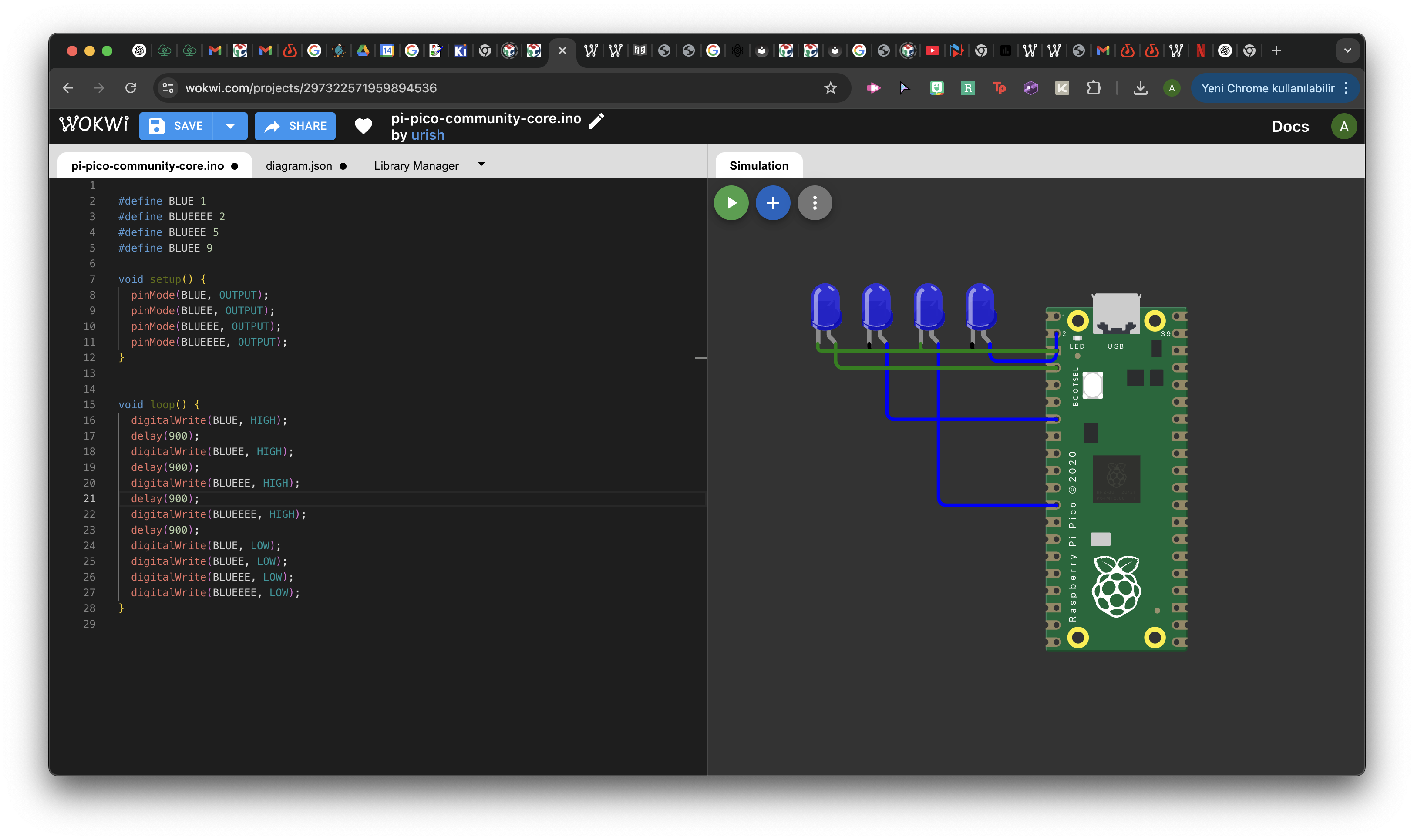
In the setup() function, I initialized each pin as an OUTPUT using pinMode(). Then in the loop() function, I turned each LED on with a delay() of 900ms, creating a step-by-step lighting effect. After all LEDs were on, I turned them all off at once using digitalWrite(..., LOW).
Basically, I defined each LED and programmed the blinking sequence using the following code:
#define BLUE 1
#define BLUEEEE 2
#define BLUEEE 5
#define BLUEE 9

void setup() {
  pinMode(BLUE, OUTPUT);
  pinMode(BLUEEEE, OUTPUT);
  pinMode(BLUEEE, OUTPUT);
  pinMode(BLUEE, OUTPUT);
}

void loop() {
  digitalWrite(BLUE, HIGH);
  delay(900);
  digitalWrite(BLUEEEE, HIGH);
  delay(900);
  digitalWrite(BLUEEE, HIGH);
  delay(900);
  digitalWrite(BLUEE, HIGH);
  delay(900);

  digitalWrite(BLUE, LOW);
  digitalWrite(BLUEEEE, LOW);
  digitalWrite(BLUEEE, LOW);
  digitalWrite(BLUEE, LOW);
}
Each LED turned on with a 900ms delay in sequence, then all turned off together. The simulation worked perfectly.
4. Recreated the Setup in Real Life Using Arduino IDE
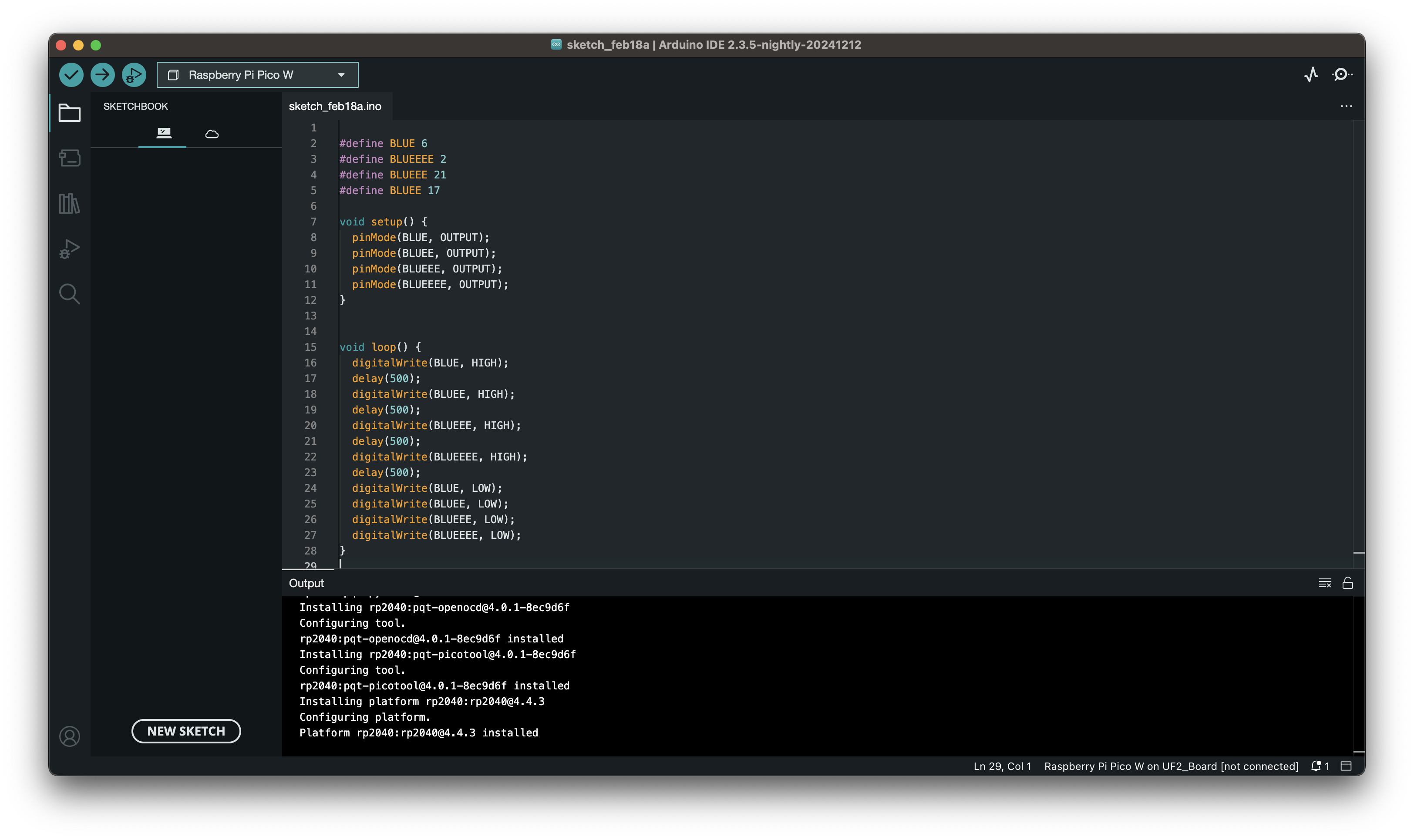
After verifying the behavior in Wokwi, I recreated the exact setup in real life. I opened Arduino IDE, selected the Raspberry Pi Pico, connected 4 blue LEDs to GPIO pins 1, 2, 5, and 9, and uploaded the same code.
In the IDE, I used the same code as in simulation, and observed the LEDs blinking sequentially on real hardware.