This week, after learning I2C communication, I used my own PCB with a XIAO-ESP32-C3 (master) to communicate. It is connected to a computer to read serial input (keyboard 1 or 2) and control the LED connected to D7 on the Arduino (slave). I also used an Arduino UNO to create an RFID door lock system.
Learning Objectives
Group Assignment
Send a message between two projects.
Individual Assignment
design, build and connect wired or wireless node(s) with network or bus addresses and a local input and/or output devices.
Learning highlights
I2C communication(XIAO-ESP32-C3 & Arduino Uno)
An RFID Door Lock System
I used AI-assisted tools to help me learn and understand Embedded Networking and Communications, as well as I2C communication.
Group Assignment
1.1 Embedded Network and Communication
Refers to how these systems exchange information via wired or wireless networks to achieve collaboration and control.
1.2 Common Communication Methods
Type
Common Protocol
Features
Applicable Scenarios
Wired
UART
Simple, point-to-point
Direct communication between Arduino UNO, Xiao ESP32
I2C
Supports multi-master/multi-slave, two-wire bus
Multiple sensors, multi-slave control
SPI
High-speed, full duplex
Sensors, high-speed peripherals
Wireless
Wi-Fi
Long distance, Internet access
Smart home, remote monitoring
Bluetooth/BLE
Low power, short distance
Mobile interaction, data synchronization
LoRa
Ultra long distance, low speed
IoT, sensor networks
Zigbee
Self-organizing, low power
Smart home, sensor networks
2.1 I2C Communication
I2C (Inter-Integrated Circuit) is a two-wire, synchronous, half-duplex, master-slave serial communication bus developed by Philips (now NXP).
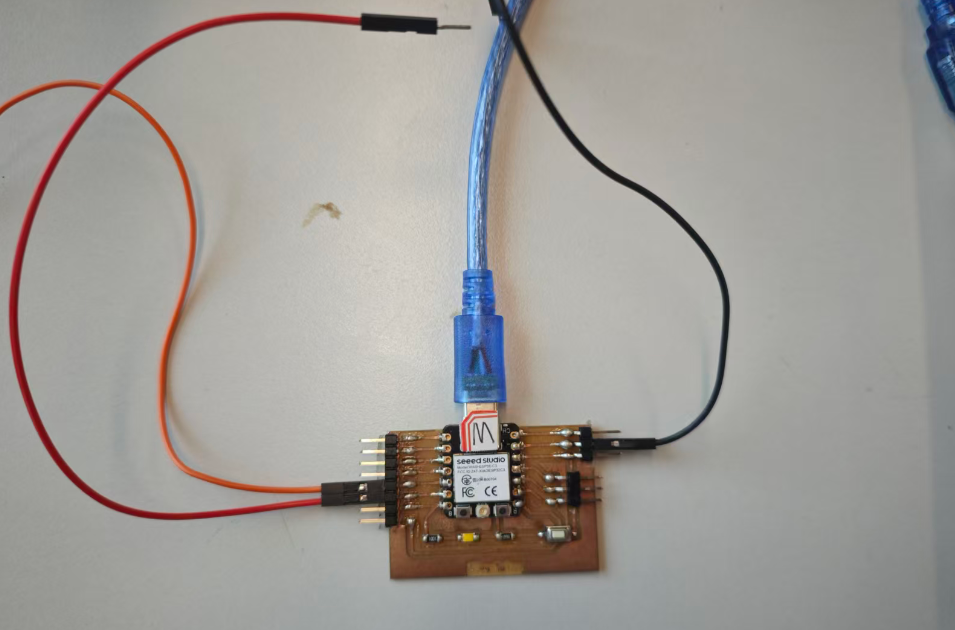
After learning I2C communication, I used my own PCB with a XIAO-ESP32-C3 (master) to communicate. It is connected to a computer to read serial input (keyboard 1 or 2) and control the LED connected to D7 on the Arduino (slave)
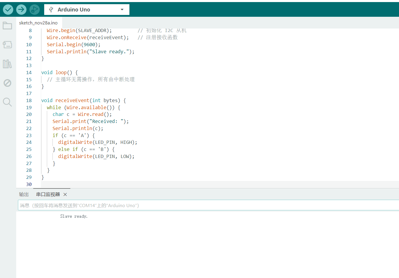
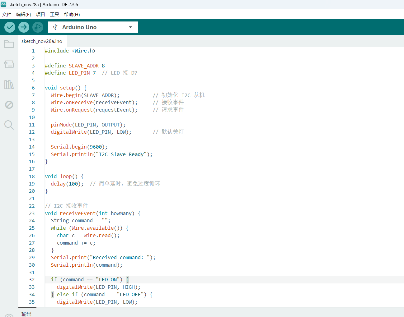
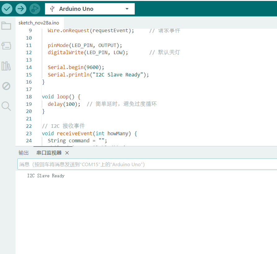
1.1 Upload Slave Code
LED connection
code
Serial output: I2C Slave Ready
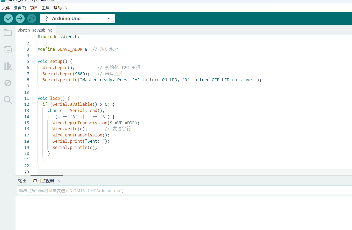
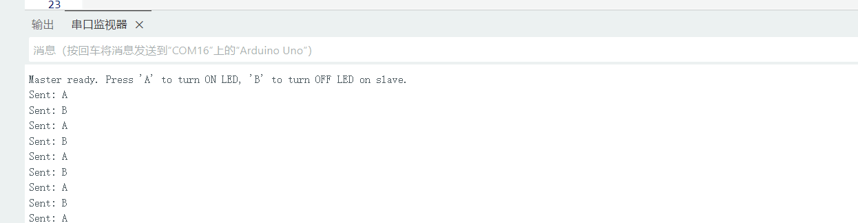
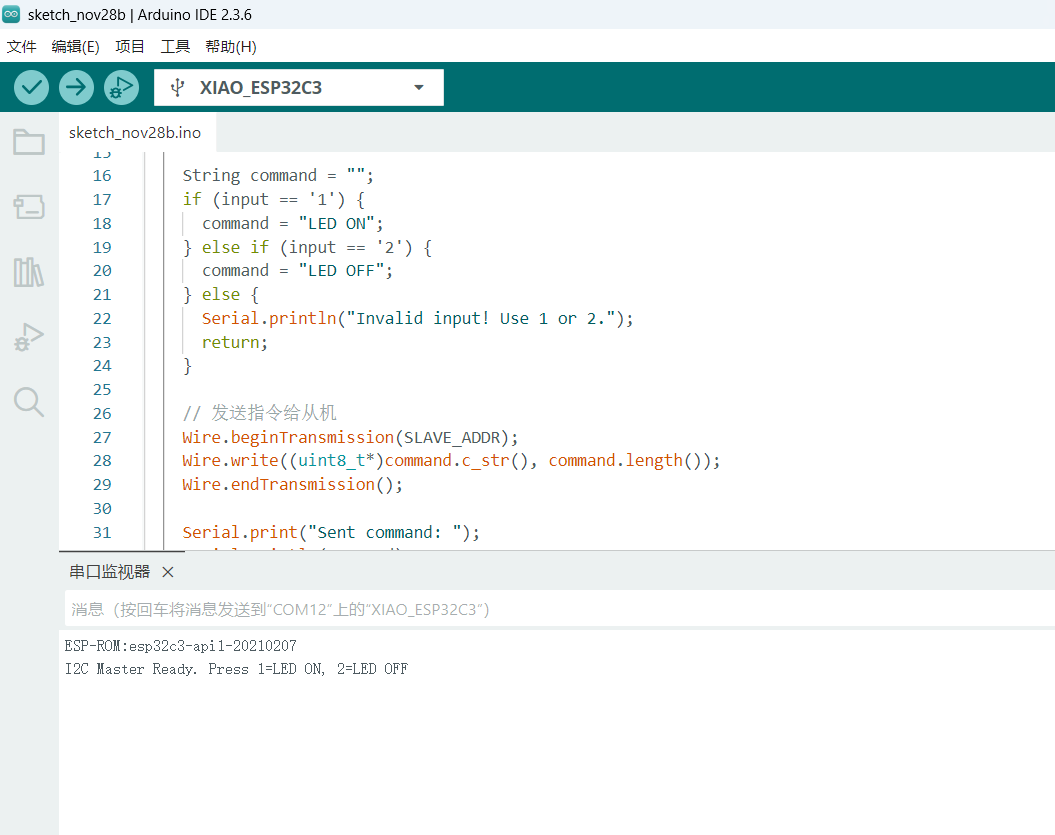
1.2 Upload Master Code
code
The serial monitor shows: ESP-ROM: esp32c3-api1-20210207
I2C Master is ready. Press 1 to turn the LED ON, 2 to turn it OFF.
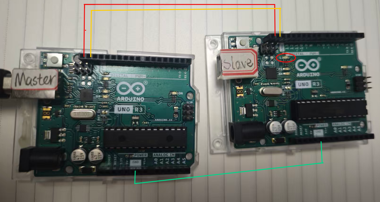
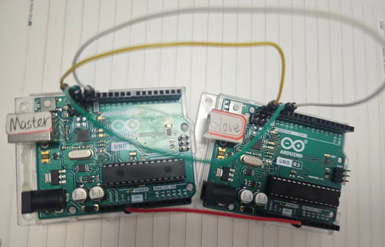
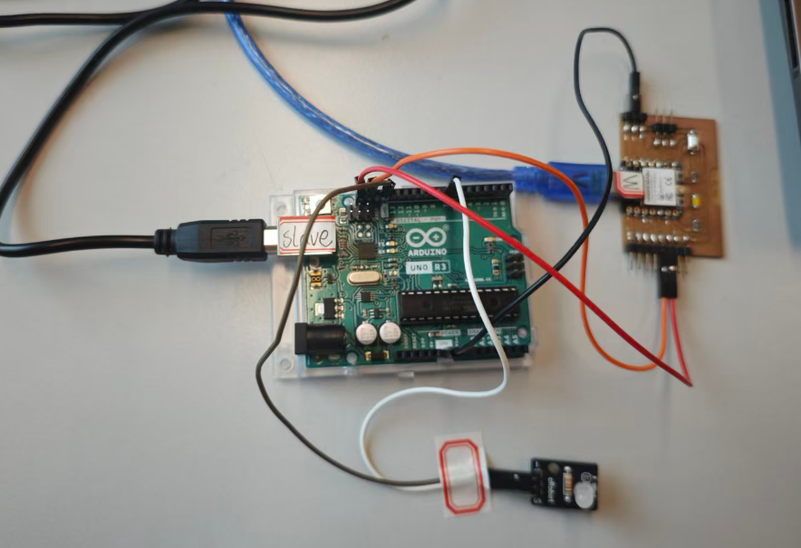
1.3 Hardware Connection
Signal
ESP32-C3
Arduino Uno
SDA
D6
SDA
SCL
D7
SCL
GND
GND
GND
LED
—
D7 → LED → GND
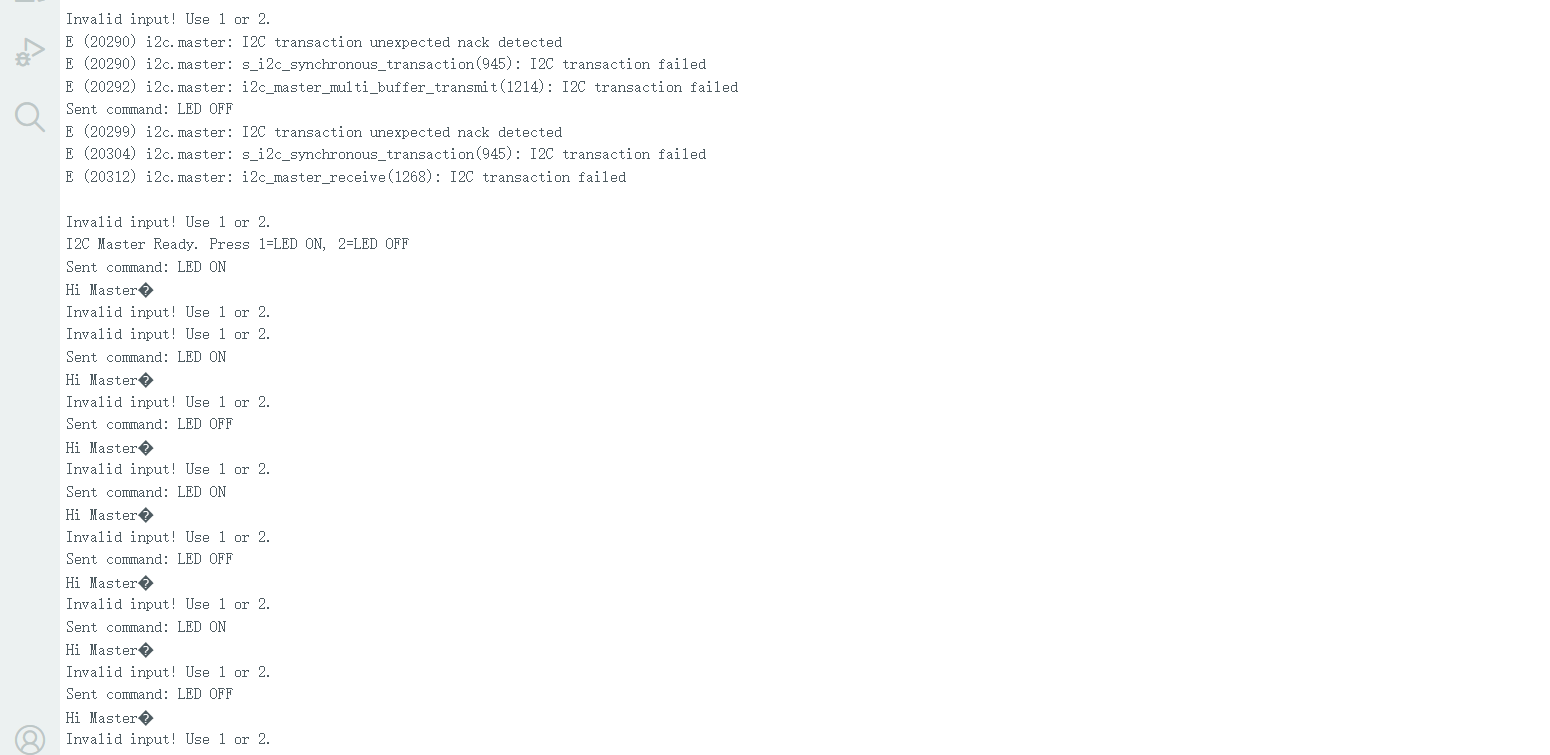
1.4 Test
Press 1 on the keyboard → LED turns on; Press 2 on the keyboard → LED turns off.
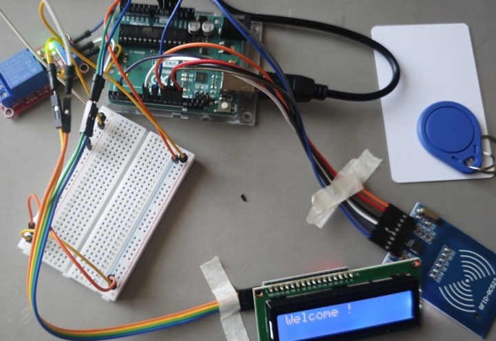
In an access control system, the RC522 module is used to detect RFID cards and read their UID. The node sends the UID to the master controller through a wired I2C connection. The master controller then parses the UID and instructs the display to record and show the information.
1 Introduction
1.1 RFID
RFID uses electromagnetic waves in the radio frequency spectrum for communication and data transfer. RFID tags are used in many industries and we can find them in product tags from stores to security access cards. RFID tags can expedite the checkout and can be used for antitheft measures.
Components of an RFID System An RFID system typically consists of several main components, each playing a different role in the system.
Component
Description
RFID Tag
Used to store and transmit information.
RFID Reader
Reads the data from the RFID tag by emitting radio waves. It communicates with a microcontroller or computer.
Antenna
Transmits and receives radio waves between the RFID tag and reader, influencing the system's range and performance.
Middleware
Software that manages and processes the data between the RFID system and application, facilitating communication with the database.
Software
Used to process and manage the data from RFID tags and integrate it into applications (e.g., security, inventory management).
Database
Stores the RFID tag information and related data, enabling real-time updates and retrieval of relevant data for processing.
Power Supply
Provides necessary power for the RFID system, especially for active tags and readers.
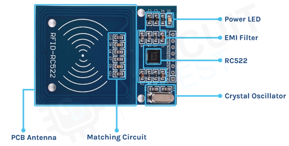
1.3 RC522 RFID
The RC522 RFID is a popular RFID reader/writer module that communicates with microcontrollers like Arduino. It uses the MFRC522 chip and supports reading and writing of 13.56 MHz RFID cards/tags.
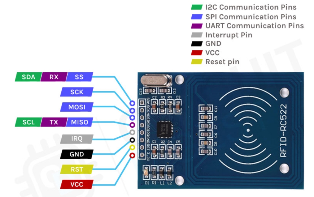
RC522 RFID Module Pins and Descriptions
Pin
Description
SDA / SCL
I2C Communication pins: Data (SDA) and Clock (SCL).
SS / SCK / MOSI / MISO
SPI Communication pins: Slave Select (SS), Clock (SCK), Master Out Slave In (MOSI), and Master In Slave Out (MISO).
RX / TX
UART Communication pins for serial data transmission.
IRQ
Interrupt signal from the module to indicate RFID tag detection.
GND
Ground pin that needs to be connected to the GND pin on the Arduino.
RST
Reset pin for the module.
VCC
Supply pin for the module. The supply voltage ranges from 2.5V to 3.3V and must be connected to the 3.3V pin on the Arduino.
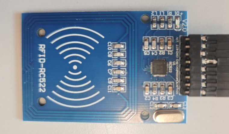
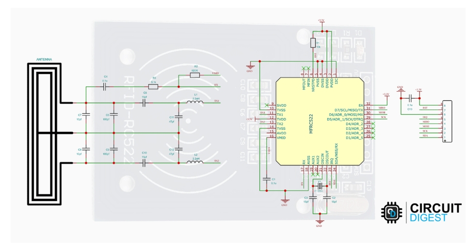
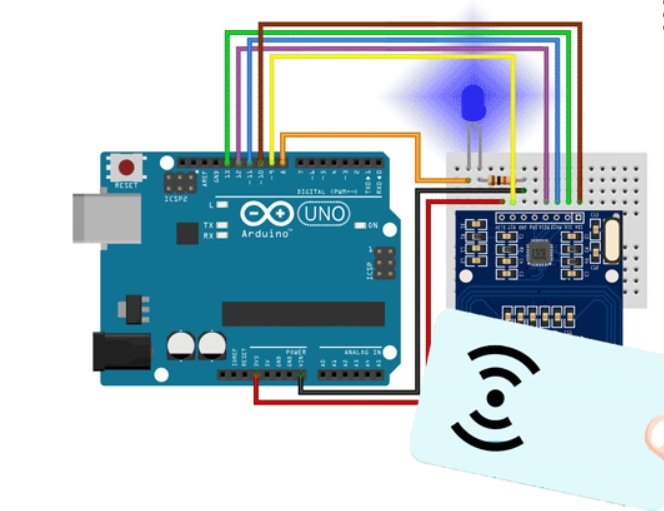
RC522 RFID Reader/Writer Module|Parts&Circuit Diagram
2 Circuit Setup
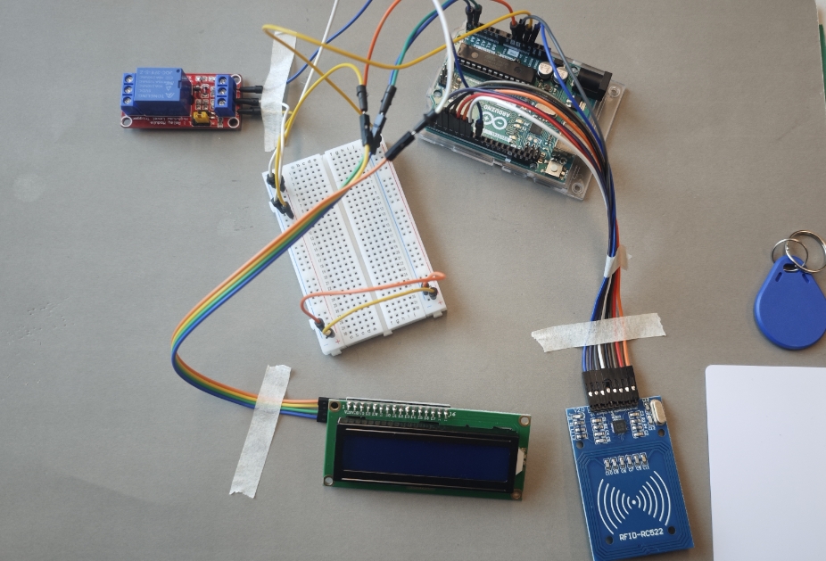
2.1 Components
RFID Module & Arduino Uno Board & RFID Key Tag & Relay Module & I2C LCD1602 & Breadboard & Jumper Wires
2.2 Circuit Setup
2.2.1 RFID Module
RFID Module
Arduino Uno
3.3V
3.3V
GND
GND
RST
2
SDA (SS)
10
MOSI
11
MISO
12
SCK
13
IRQ
7
2.2.2 I2C LCD1602
I2C LCD1602
Arduino Uno
GND
GND
VCC
5V
SDA
A4
SCL
A5
2.2.3 Relay Module
Relay Module
Arduino Uno
SIG
8
VCC
5V
GND
GND
3 Reading an RFID Tag
3.1 Installing the MFRC522 Library
Open Arduino IDE.
Click Tools → Manage Libraries (S+C+M)
In the search bar, type: MFRC522.
Find MFRC522 by GithubCommunity.
Click the Install button.
Notes:Place the RFID key tag near the center of the reader
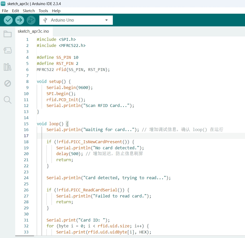
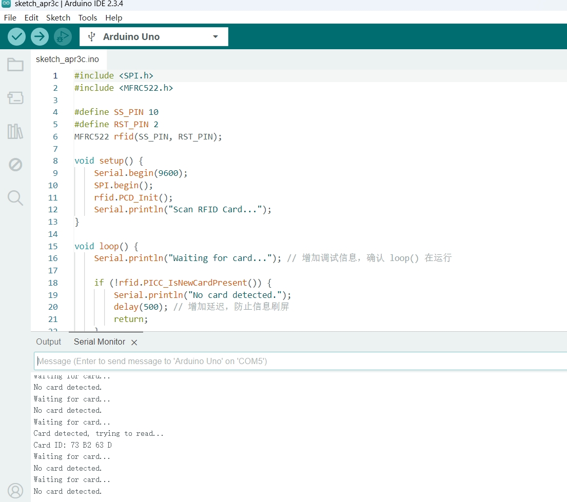
3.2 Test Code
#include <SPI.h>
#include <MFRC522.h>

#define SS_PIN 10
#define RST_PIN 2
MFRC522 rfid(SS_PIN, RST_PIN);

void setup() {
    Serial.begin(9600);
    SPI.begin();
    rfid.PCD_Init();
    Serial.println("Scan RFID Card...");
}

void loop() {
    if (!rfid.PICC_IsNewCardPresent()) {
        return;
    }
    if (!rfid.PICC_ReadCardSerial()) {
        return;
    }
    Serial.print("Card ID: ");
    for (byte i = 0; i < rfid.uid.size; i++) {
        Serial.print(rfid.uid.uidByte[i], HEX);
        Serial.print(" ");
    }
    Serial.println();
    rfid.PICC_HaltA();
}
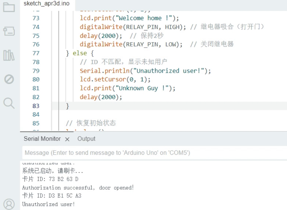
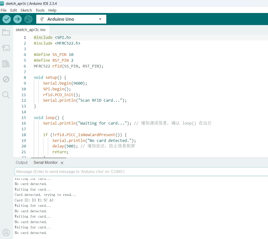
3.3 Card ID
Serial Debugging: Viewing scanned card IDs in the Serial Monitor.
Card ID 1: 73 B2 63 D
Card ID 2: D3 E1 5C A3
RFID Serial Monitor Output & Troubleshooting
Serial Monitor Output
Possible Issue
Suggested Solution
⚠ ERROR: RFID module not detected
Wiring issue or incorrect power supply
ensure standard SPI pins and 3.3V power are used
No card detected
No RFID card detected near reader
Try a different RFID card, adjust scanning angle, or ensure the card is 13.56MHz.
Failed to read card
Read failure due to card or hardware issue
Try another card, adjust timing (add delay), or test another RFID module.
Card ID: xx xx xx xx
Success
RFID card read successfully. Use this ID for verification logic.
Reading RFID Cards: Detecting nearby cards and retrieving their IDs.
LCD Display: Showing card ID and access status on the LCD1602 screen.
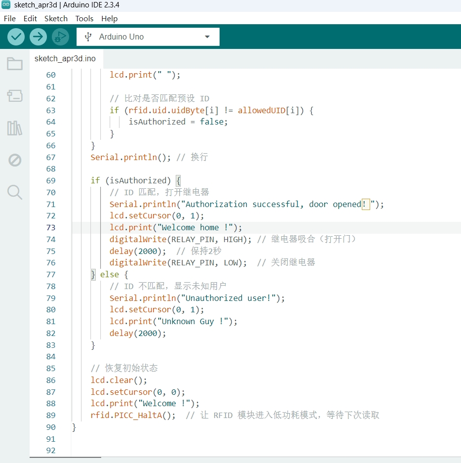
Relay Control: Unlocking the door if the RFID card matches.
Serial DebuggingC OPEN & CLOSE
Run Results
At the beginning, we can see "Welcome!" displayed on the I2C LCD1602.
Swipe Card 1, and the relay's normally open contact will activate. The LCD will display:
"ID: 73 B2 63 D"
"Welcome Home!"
After two seconds, it will return to displaying "Welcome!".
Swipe Card 2, and if the ID is incorrect, the relay's normally open contact will deactivate. The LCD will display:
"ID: D3 E1 5C A3"
"Unknown Guy!"
After two seconds, it will return to displaying "Welcome!".
video
6 Issues and Solutions
Issue: RFID reader not detecting tags → Check wiring and power supply.
Issue: Incorrect card ID → Print the card ID in Serial Monitor to verify.
Issue: LCD not displaying correctly → Ensure the correct I2C address is used.
7 Conclusion
This project demonstrates how RFID technology can be used for access control. The combination of an RFID reader, LCD display, and relay allows for a secure and user-friendly door lock system.