Fab Academy
My previous experience was limited to using vinyl stickers for home decor years ago. I found the installation process tedious, particularly the weeding and the challenge of applying the vinyl without tearing it. Despite this, I was always fascinated by the design versatility it offered.
Regarding laser cutting, Neil explained in class that it is primarily a subtractive process, as it removes material from a sheet. This immediately made me consider the importance of optimizing material usage to minimize waste.
At the Fab Lab ESAN, I observed various laser-cut projects, such as assemble-able figures, keychains, and trophies made from MDF and acrylic. In one instance, I even saw a project that used fish leather for a clothing application.
This week's work was carried out in February 2025, during my first Fab Academy cycle. It was my first hands-on experience with the vinyl cutter and the laser cutter at ESAN Fab Lab — and, not coincidentally, my first time cutting a Snoopy image, which would become a recurring visual thread throughout my Fab Academy journey and into my final project. The parametric construction kit exercise introduced me to the concept of kerf, press-fit joints, and the relationship between digital design decisions and physical fabrication outcomes. That systems-level thinking — understanding how a design constraint flows downstream into a material consequence — stayed with me through every subsequent week, including the CNC machining and PCB milling I completed in 2025 and 2026.
You can download the files I used to complete this week's assignment with this link
Exploring laser and vinyl cutting
This week I learned many new things!! Let's see:
Individual assignment
1. Cut something on the vinyl cutter
2. Design, laser cut, and document a parametric construction kit, accounting for the laser cutter's kerf, which can be assembled in multiple ways, and for the extra credit include elements that aren't flat
3. extra credit: include elements that aren't flat
4. extra credit: engrave as well as cut
Group assignment
1. Do your lab's safety training
2. Characterize your laser cutter's focus, power, speed, rate, kerf, joint clearance and types
My previous experience was limited to using vinyl stickers for home decor years ago. I found the installation process tedious, particularly the weeding and the challenge of applying the vinyl without tearing it. Despite this, I was always fascinated by the design versatility it offered.
Regarding laser cutting, Neil explained in class that it is primarily a subtractive process, as it removes material from a sheet. This immediately made me consider the importance of optimizing material usage to minimize waste.
At the Fab Lab ESAN, I observed various laser-cut projects, such as assemble-able figures, keychains, and trophies made from MDF and acrylic. In one instance, I even saw a project that used fish leather for a clothing application.
This week's work was carried out in February 2025, during my first Fab Academy cycle. It was my first hands-on experience with the vinyl cutter and the laser cutter at ESAN Fab Lab — and, not coincidentally, my first time cutting a Snoopy image, which would become a recurring visual thread throughout my Fab Academy journey and into my final project. The parametric construction kit exercise introduced me to the concept of kerf, press-fit joints, and the relationship between digital design decisions and physical fabrication outcomes. That systems-level thinking — understanding how a design constraint flows downstream into a material consequence — stayed with me through every subsequent week, including the CNC machining and PCB milling I completed in 2025 and 2026.
Group assignment
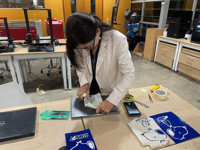
I worked with my colleague Jhasmin Ayala
Check this link
Individual assignment
1. Cut something on the vinyl cutter
I followed these steps:
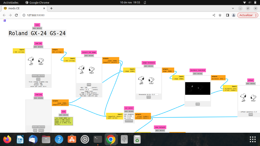
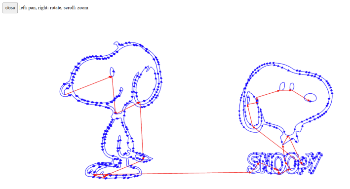
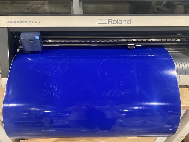
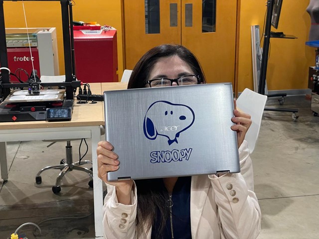
a. Choose an image: Select an image to cut. For example, I chose an image of Snoopy (my favorite character)
b. Get an image in svg or png format.
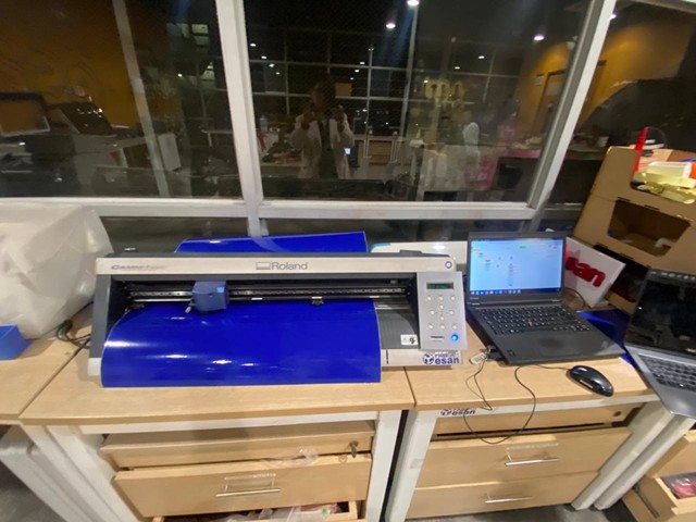
c. Print the image: I used the Roland CAMM-1, a smaller vinyl cutter. For printing, I used mods project, a modular cross-platform tool for fab labs.
d. I configure the cutting parameters:
- Force: 120
- Speed: 2

e. I upload my SVG image and calculate the cut raster.
f. Preview
g. I begin cutting the vinyl.
h. I remove the cut pieces and cover them with transfer paper.
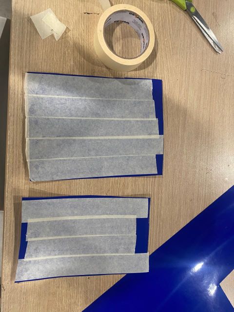
i. With the help of tweezers, I remove the transfer paper from the vinyl with the pieces I want to transfer to my new surface.
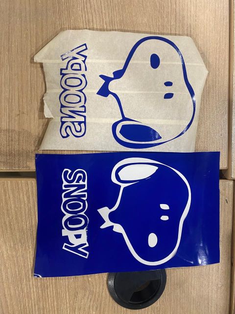
j. I stick the paper transfer onto the new surface.
k. I remove the transfer paper and with the help of tweezers I make sure that only the vinyl remains stuck to the new surface.
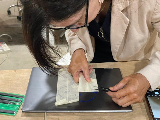
l. With a lot of patience... I peeled off the image, and voila!
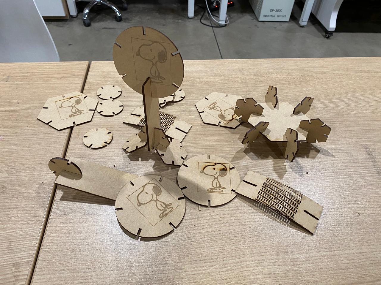
2. Design, laser cut, and document a parametric construction kit, accounting for the laser cutter's kerf, which can be assembled in multiple ways, and for extra credit include elements that aren't flat
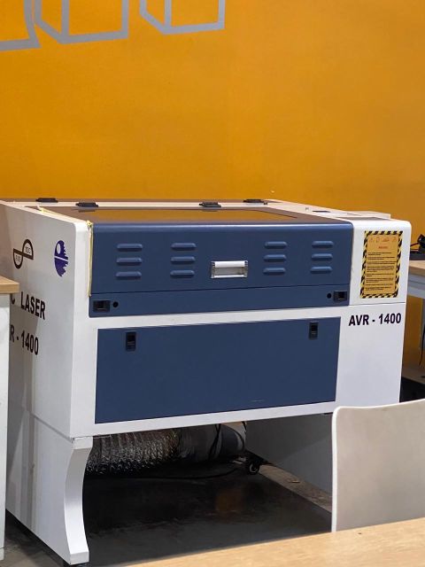
Machines: At Fab Lab ESAN, we had two machines:
AVR-1400
Trotec Speedy 400
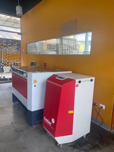
Unfortunately, Trotec Speedy 400 was in maintenance, so this week i didn't have the chance to use it.
Kerf: I used different measures to find the kerf for my parametric design. Considering the width of the material I'm using (MDF), the kerf i'll be considering is 0.125 mm.
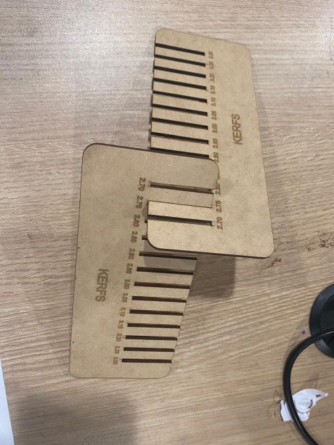
I followed these steps:
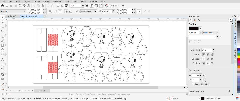
a. Design a parametric model: Open a new design in Fusion360, create a sketch. Create parameters: Radius small and big, thickness, kerf and side (depth). It was so useful because when I had to work with another form, I just created some formulas like radius*2, thickness+kerf*2.

b. Create circles and polygons. Use the circular pattern tool to automatically generate equal and equidistant cuts. For the circle, I used 5 cuts, and for the polygon, I used 6 cuts. Create a flexible piece: Add a rectangle and include a pattern in the center to make it flexible. I recommend checking all the lines of the chosen design to ensure the piece won'tbe completely cut, especially the top and bottom lines. Extrude all the profiles.

c. Open a new sketch and project the geometries. Save the file as a DXF.

d. Prepare to engrave and cut: Import the file in Corel Draw, select the images and text to be engraved, and group them, select the circles and polygons, and group them for cutting.
e. Parameters for engraving: Power 15, speed 200. Parameters for cutting: Power 40, speed 20.

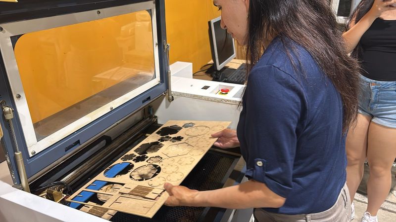
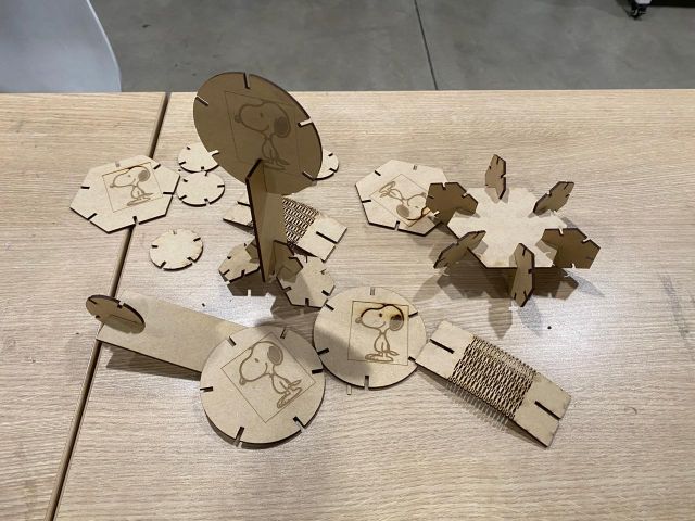
c. Final assembly: Remove the pieces from the machine and start assembling the designs. Work done!
Reflections
• Designing the vinyl turned out to be much simpler than I expected. Modern design software is intuitive and allows for great creativity. However, it confirmed that patience is key during the weeding process to avoid ruining the design.
• Having access to these machines at the Fab Lab ESAN is a significant advantage for our community. For an entrepreneur or student, acquiring a laser cutter is a major investment, but using the lab's equipment makes the variable cost per unit much lower, facilitating prototyping.
• This session changed my perspective on products I usually consume, like 3D puzzles. I used to only look at the final product, but now I analyze the pieces more carefully: their symmetry, the kerf allowance, and the cutting precision for a perfect fit.
• In summary, the techniques learned this week expanded my understanding of the applications possible with the lab's resources, highlighting two key aspects:
o Easy and efficient prototyping for iterating designs with high precision.
o Material use efficiency, minimizing waste and reducing costs, which aligns with sustainable principles.
You can download the files I used to complete this week's assignment with this link