Individual assignment Design and document the system integration for your final project.
What I knew beforehand
When I think of systems integration, I envision an orderly box where everything is harmoniously placed, allowing the whole to function correctly. I also believe that anyone looking at an integrated system should be able to understand the logic and function of the circuits and connections — not just the original designer.
Neglecting the organization and documentation of a system's integration can cause the project to fail at the final stage, or create lasting confusion about which component does what — a serious problem for any future audit, modification, or repair.
This documentation was produced in June 2026. System integration was, for me, the most demanding phase of the entire program — not because any single component was technically unfamiliar by this point, but because making all of them work together inside a physical enclosure requires a different kind of thinking. In my professional life I use the analogy of an organization: individual departments can function perfectly in isolation while the organization as a whole fails if coordination is absent. Pitch timer´s integration challenges — routing errors on the PCB, uneven LED diffusion, fragile roof geometry, cable management inside a constrained interior — were each solved through physical iteration rather than assumption. The result is a device that was validated by real entrepreneurs at ESAN's incubator during pitch practice sessions.
Final Project Overview
Pitch timer is designed for entrepreneurs who practice timed presentations. It solves a real problem at ESAN's business incubator: speakers lose track of time and cannot maintain eye contact with the audience while checking a phone timer. PitchLight guides the presenter through three phases using a traffic-light LED system — green, yellow, and red — with a touch display showing the countdown and a buzzer alert when time is up.
The device is a single self-contained unit: a red house enclosure fabricated entirely at the ESAN Fab Lab, housing a custom PCB, a Nextion touch display, a WS2812B LED strip behind a laser-cut acrylic diffuser, and a passive buzzer.
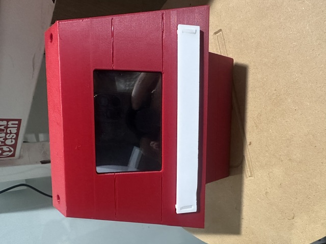
Pitch timer fully assembled — red PLA+ house enclosure, Nextion display, and white PLA+ LED diffuser cover.
The system integrates the following components:
Component
Quantity
Function
Seeed XIAO RP2040
1
Main microcontroller — runs the countdown state machine
Nextion NX4832T035 3.5" Touch Display
1
Shows remaining time in MM:SS and receives Start / Pause / Reset commands
WS2812B LED Strip
1
Traffic-light color phases: green → yellow → red + blink
Passive Buzzer
1
PWM alert when the countdown reaches zero
Custom PCB (KiCad + CNC milled)
1
Integrates all connectors for the peripherals in a single board
5V USB Power Supply
1
Powers the entire system via USB-C
How the System Works
When powered on, Pitch timer displays the home screen on the Nextion touch display. The user selects one of three timer modes by tapping the screen — 3, 4, or 5 minutes. From that point, the XIAO RP2040 runs a non-blocking state machine driven by millis(), updating the display, the LED strip, and the buzzer simultaneously without delays.
The countdown moves through three phases, each activating a different response from every output component:
🟢 Green — GO
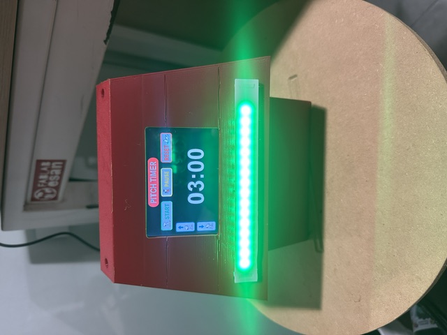
The countdown starts. All LEDs light solid green. The display shows the remaining time in MM:SS. No sound. The entrepreneur is speaking freely.
🟡 Yellow — WARN (last 60 seconds)
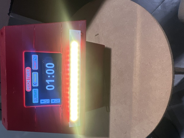
LEDs switch to solid yellow. The display continues the countdown. No sound. The presenter knows it is time to wrap up.
🔴 Red — STOP (last 10 seconds)
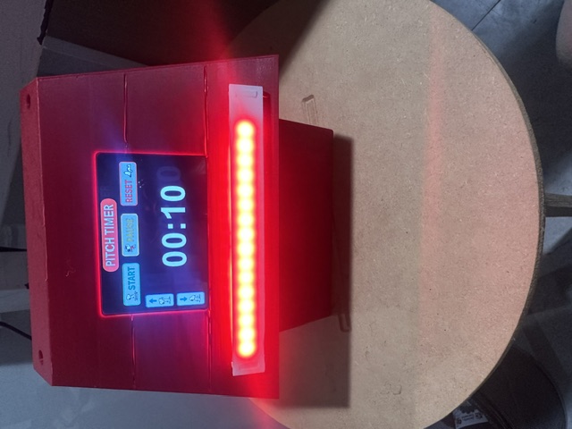
LEDs switch to red and begin blinking. The buzzer emits three short beeps. When the countdown reaches 00:00, a sustained tone plays and the system waits for a reset.
The user can press Pause at any moment to freeze the timer, or Reset to return to mode selection.
System Components
Input — what the system receives:
Component
Connection
Purpose
Nextion 3.5" Touch Display
XIAO RP2040 — UART pin D1
User selects timer mode (3 / 4 / 5 min) and sends Start, Pause, Reset commands
Output — what the system does:
Component
Connection
Purpose
Nextion 3.5" TFT Display
UART pin D1 — 9600 baud
Shows remaining time and current phase label
WS2812B LED Strip
Digital pin D9 — FastLED library
Traffic-light color phases with blink effect in red phase
Passive Buzzer
Digital pin D3 — PWM
Alert tones at phase transitions and sustained tone at time up
Pitch timer Flow
The flow below shows how Pitch timer guides the user from power-on to the end of a timed presentation. Each state specifies what the display shows, what color the LEDs are, and whether the buzzer is active — so every component has a defined role at every moment.
State 1 — Home Screen
Display: mode selection (3 / 4 / 5 min)
LEDs off · No sound
↓
User taps 3, 4, or 5 min on the touch display
↓
State 2 — Countdown Active · GO
Display: MM:SS counting down
🟢 All LEDs solid green · No sound
↓
60 seconds remaining
↓
State 3 — Warning Phase · WARN
Display: MM:SS counting down
🟡 All LEDs solid yellow · No sound
↓
10 seconds remaining
↓
State 4 — Stop Phase · STOP
Display: final seconds
🔴 LEDs red + blinking · 🔊 3 beeps
↓
Countdown reaches 00:00
↓
State 5 — Time Up
Display: 00:00
🔴 LEDs solid red · 🔊 Sustained buzzer tone
↓
User presses Reset
↓
Return to State 1 — Home Screen
The three phases in action:
🟢 Green phase — GO — display shows 03:00 at start.
🟡 Yellow phase — WARN — last 60 seconds.
🔴 Red phase — STOP — last 10 seconds, LEDs blinking.
Physical Design and Packaging
The enclosure was designed in Fusion 360 as a red house shape. The form is intentional — it aims to be memorable for entrepreneurs, associating the device with a home for their business ideas. All components are housed inside this structure, fabricated entirely at the ESAN Fab Lab using 3D printing, CNC milling, and laser cutting.
Roof and Front Panel — Display Mount
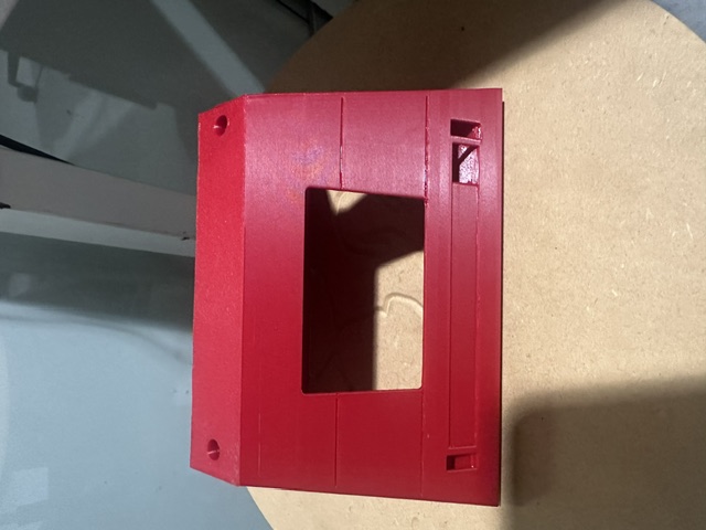
The Nextion 3.5" touch display is mounted flush on the front face of the house. The enclosure was designed with a dedicated rectangular opening sized precisely to fit the display, allowing it to sit level with the surface and giving the device a clean, integrated look. The roof is hinged to allow access to the interior for assembly and maintenance.
Front panel — rectangular opening designed to fit the Nextion display flush with the surface.
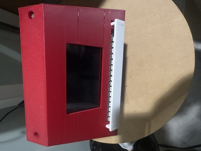
Fully assembled Pitch timer — display mounted, LED diffuser cover in place.
Base — LED Strip and Diffuser Cover
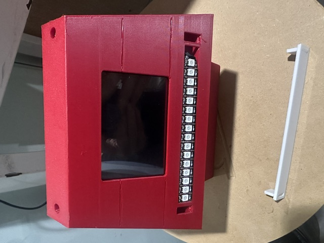
The WS2812B LED strip runs along the front base of the house, recessed into a dedicated channel. A laser-cut cover sits over it to diffuse the light. The cover material was changed during the iteration process — details in the section below.
LED strip without diffuser — individual LEDs visible, light distribution uneven.
LED strip with diffuser cover installed — light is more uniform across the bar.
Interior — PCB, Wiring, and Assembly
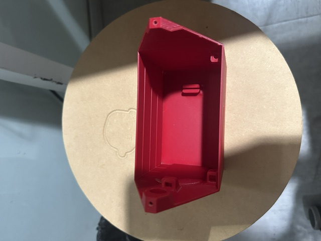
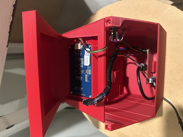
The custom-milled PCB is mounted on a platform inside the base of the house. All connectors are placed on a single side of the board, making cable routing inside the limited space straightforward. Cables are organized with a spiral wrap to keep them from interfering with the LED diffuser or the display connector. M2 Phillips screws secure the PCB platform and the display frame in place.
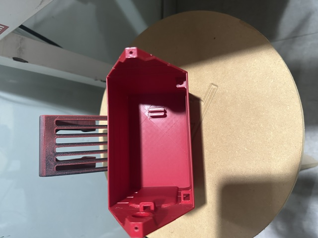
Interior of the base body — mounting clips and cable guide slots visible.
Interior with PCB mounted and cables organized using a spiral wrap. Roof open — PCB, XIAO RP2040, and organized wiring inside the red PLA+ enclosure.
Iteration Process
Each part of the enclosure was printed and tested separately before assembling a complete version. This revealed several problems that required redesign.
Roof — First version had print-in-place hinge issues
The first roof version included a ventilation grille printed as a single piece. The layer adhesion on the thin grille slats was weak, making the structure fragile. The roof was redesigned to remove the decorative grille and simplify the geometry, improving print reliability and structural strength.
First roof iteration — ventilation grille printed as part of the roof. The slats were fragile and the design was simplified in the final version.
LED Diffuser Cover — Material change from PLA+ to acrylic
The first diffuser cover was printed in white PLA+. During testing, the light distribution was uneven — the LEDs produced visible hot spots through the semi-opaque material. The cover was replaced with a laser-cut transparent acrylic piece, which distributes the light evenly across the full length of the strip with no hot spots.
PCB — Routing errors required redesign and re-milling
The first PCB version had routing errors that caused incorrect connections between the XIAO RP2040 and the LED strip connector. The board was redesigned in KiCad and re-milled on the Makera Carvera. The second version was verified with a multimeter before components were soldered.
Phase thresholds — Calibrated through user testing
The yellow and red phase durations (60 s and 10 s respectively) were calibrated through testing sessions with entrepreneurs at the ESAN´s business incubator. The values were confirmed to be intuitive — 100% of users understood the color transitions without any prior explanation.
Current State
Pitch timer is fully assembled and operational. All subsystems are integrated inside the house enclosure and the complete flow — mode selection, countdown, phase transitions, buzzer alert, and reset — functions correctly.
Component / Subsystem
Status
XIAO RP2040 — Custom milled PCB
✅ Working
Nextion 3.5" Touch Display
✅ Working — countdown and UI functional
WS2812B LED Strip
✅ Working — three-phase color control tested
Passive Buzzer
✅ Working — PWM frequency calibrated
Acrylic LED diffuser cover
✅ Working — even light distribution confirmed
Red PLA+ house enclosure
✅ Printed and assembled
Firmware — non-blocking millis() state machine
✅ Working — all three modes functional
Full system flow (mode → countdown → alert → reset)
✅ Complete — validated with real users at ESAN´s business incubator
Reflections
There is a fundamental difference between a "collection of parts" and a robust integration of those parts into a product. A collection of parts that individually work correctly can still fail as a system if their physical arrangement, cable routing, power distribution, or mechanical constraints have not been thought through together.
Achieving integration requires being organized throughout the entire development process — not just at the end. The design layout must maintain that order, allow for access during maintenance, and, where relevant, support portability or replication by others.
That´s why system integration was the most demanding phase of this project. Fitting the Nextion display, PCB, and LED strip inside the house while keeping cables organized, light distribution even, and all connectors accessible required several design iterations. Each problem — routing errors on the PCB, uneven LED diffusion, fragile roof geometry — was solved through physical testing rather than assumption. The result is a compact, self-contained device that works reliably in a real presentation context and has been validated by entrepreneurs at the ESAN incubator.