
W7 | Computer-Controlled Machining
📝 Group Assignment:
- Complete your lab's safety training
- Test runout, alignment, fixturing, speeds, feeds, materials and toolpaths for your machine
- Document your work to the group work page and reflect on your individual page what you learned
What We did
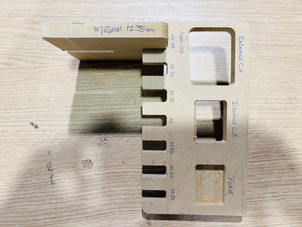
As a group, we worked with the ShopBot Alpha PRS 96x60, beginning with safety training covering PPE requirements, machine operation procedures, and emergency protocols. We learned how to properly secure the material to the spoilboard, set up and calibrate the machine, and import and run toolpaths using the ShopBot CNC software. We also explored the machine's capabilities by evaluating alignment, suitable materials, cutting parameters (speeds and feeds), and toolpath strategies in VCarve Pro. To determine the kerf for our material, we milled a press-fit tolerance tester with slots of different widths. The results indicated a kerf of 0.2 mm (material thickness: 12.35 mm; best-fitting slot: 12.75 mm). This value proved essential for accurately designing the press-fit joints used in our individual projects.
To see the full process in detail — you can visit the folowing page here.
What I Learned
Safety
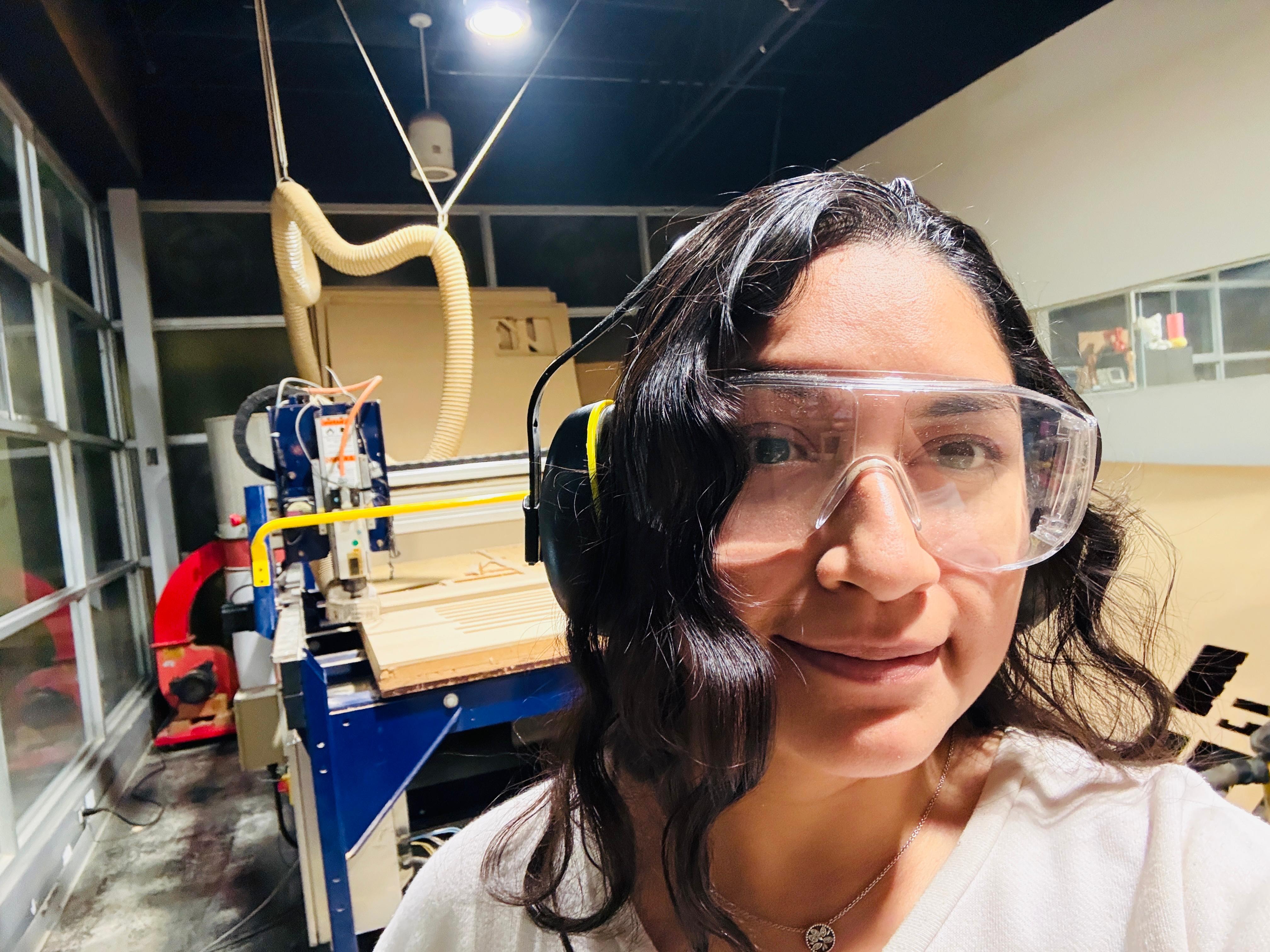
The safety training reinforced how important it is to give a CNC router your full attention at all times. This is not a machine that can ever be left unattended. Someone must always be present, closely monitoring the cut and listening to the sound of the spindle, since any unusual noise can be an early sign that something is wrong. If that happens, the emergency stop button must be within immediate reach so the machine can be stopped without delay. On the PPE side, safety glasses and ear protection are non-negotiable: the spindle runs at high RPM and generates a noise level that, with prolonged exposure, can seriously damage your hearing. Dust extraction also needs to be running throughout the entire job — MDF dust is harmful if inhaled over time.
Machine Characterization
Beyond safety, the group tests reinforced the importance of properly characterizing the machine before starting any fabrication. Seeing how speeds, feeds, and toolpath strategies directly affect the quality of the cut confirmed that these parameters must be selected carefully for each material and operation. The tests also reinforced the importance of accounting for details such as the kerf value and the order of the toolpaths, since both have a direct impact on the accuracy of the final parts and whether press-fit joints assemble correctly.
📝 Individual Assignment:
- Make (design+mill+assemble) something big
Make Something Big
Backlit Sign
The Challenge
For this week's assignment, I took on the challenge of designing, CNC milling, and assembling a large-scale object — approximately one meter in size. The goal was to apply everything I had learned about CNC milling, and after training with the ShopBot PRS Alpha, it was time to put it into practice. The perfect opportunity came up through a challenge proposed by one of the university's departments: creating a backlit sign featuring their logo, where each letter and the base had to be illuminated, with all the wiring completely hidden. I accepted the challenge and got to work! 👩🔧

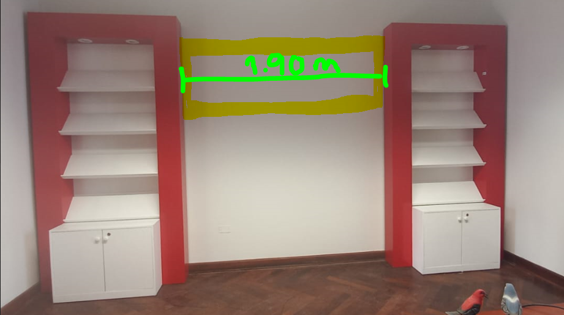
We were provided with a reference image of the design, along with the required dimensions and the designated installation space.
Designing
1 Material & Tolerance Test
Before jumping into the design, I chose 12mm MDF as the material. To ensure a proper fit for the press-fit joints, I first milled a tolerance test. The result showed a kerf of 0.2mm, which I took into account throughout the entire design process.
2 3D Design — Autodesk Inventor
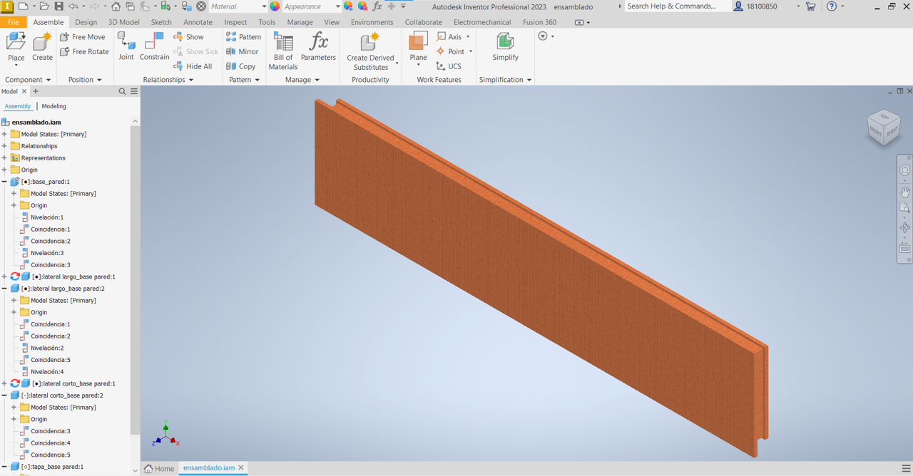
In Autodesk Inventor, I designed the structural components of the project: the back box pieces with their press-fit joints, the front board, and the grooves on the back of the board to house the LED strips.
3 2D Design — CorelDRAW
For the letters and their connections to the board, I worked in CorelDRAW. Since the CNC router also works with vectors — just like the laser cutter — I vectorized the logo and designed the joints between the letters and the board, as well as any additional adjustments the board required.
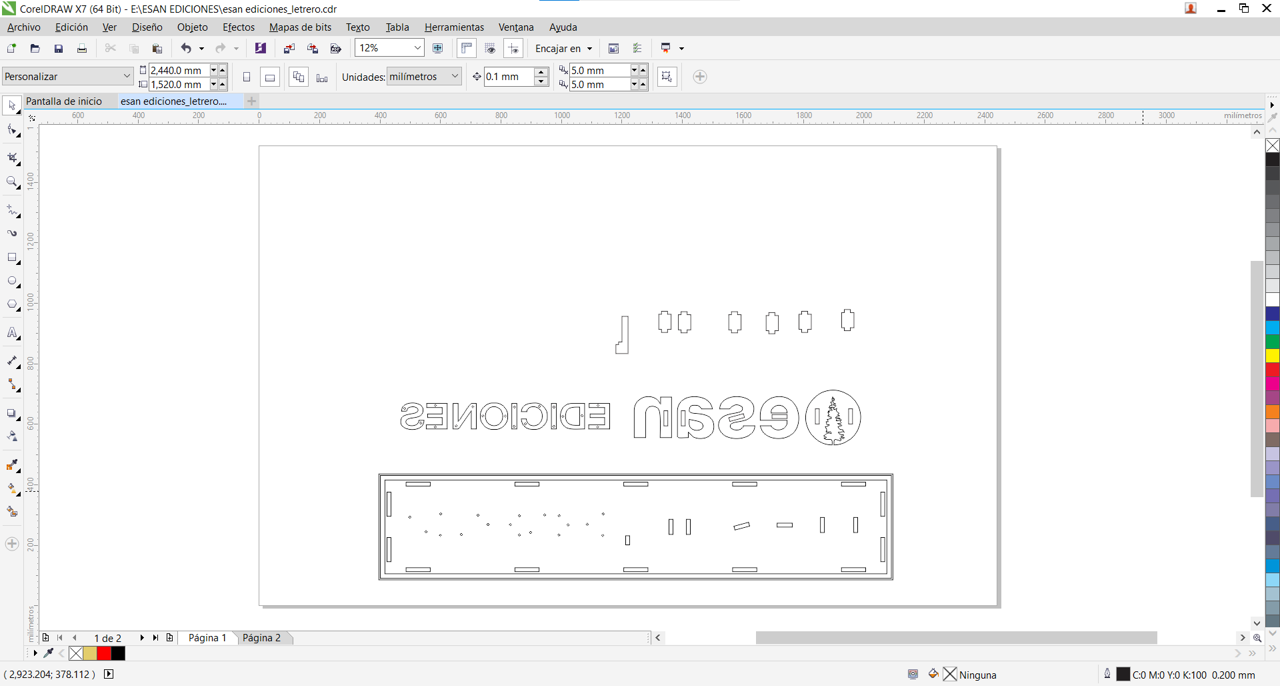
1 CAM — VCarve Pro
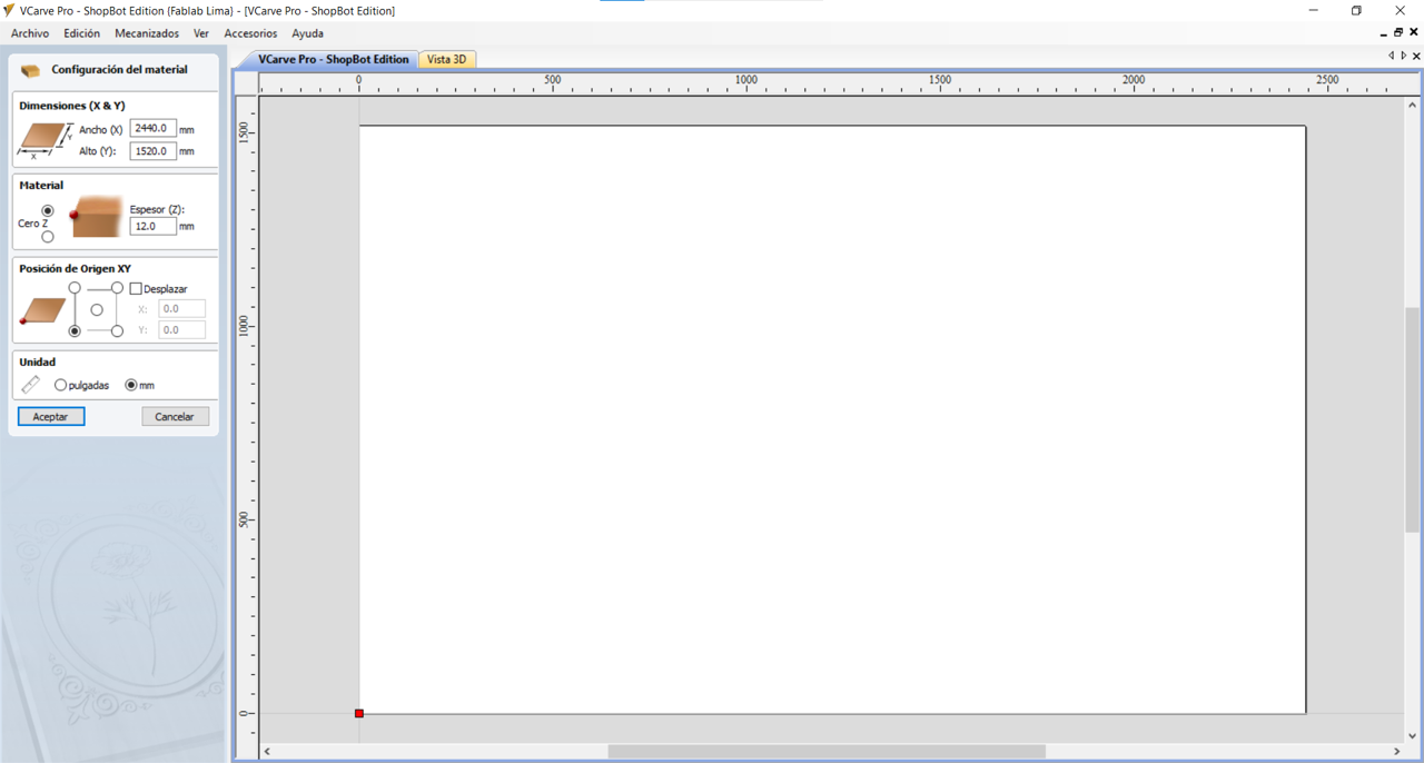
Before generating the toolpaths, the first step was to set up the job in VCarve Pro 7.5 ShopBot Edition by entering the material dimensions and depth — 2440 x 1520 x 12mm. Then I imported the pieces previously exported as DXF files from both Autodesk Inventor and CorelDRAW, and arranged them across the board to make the most of the material.
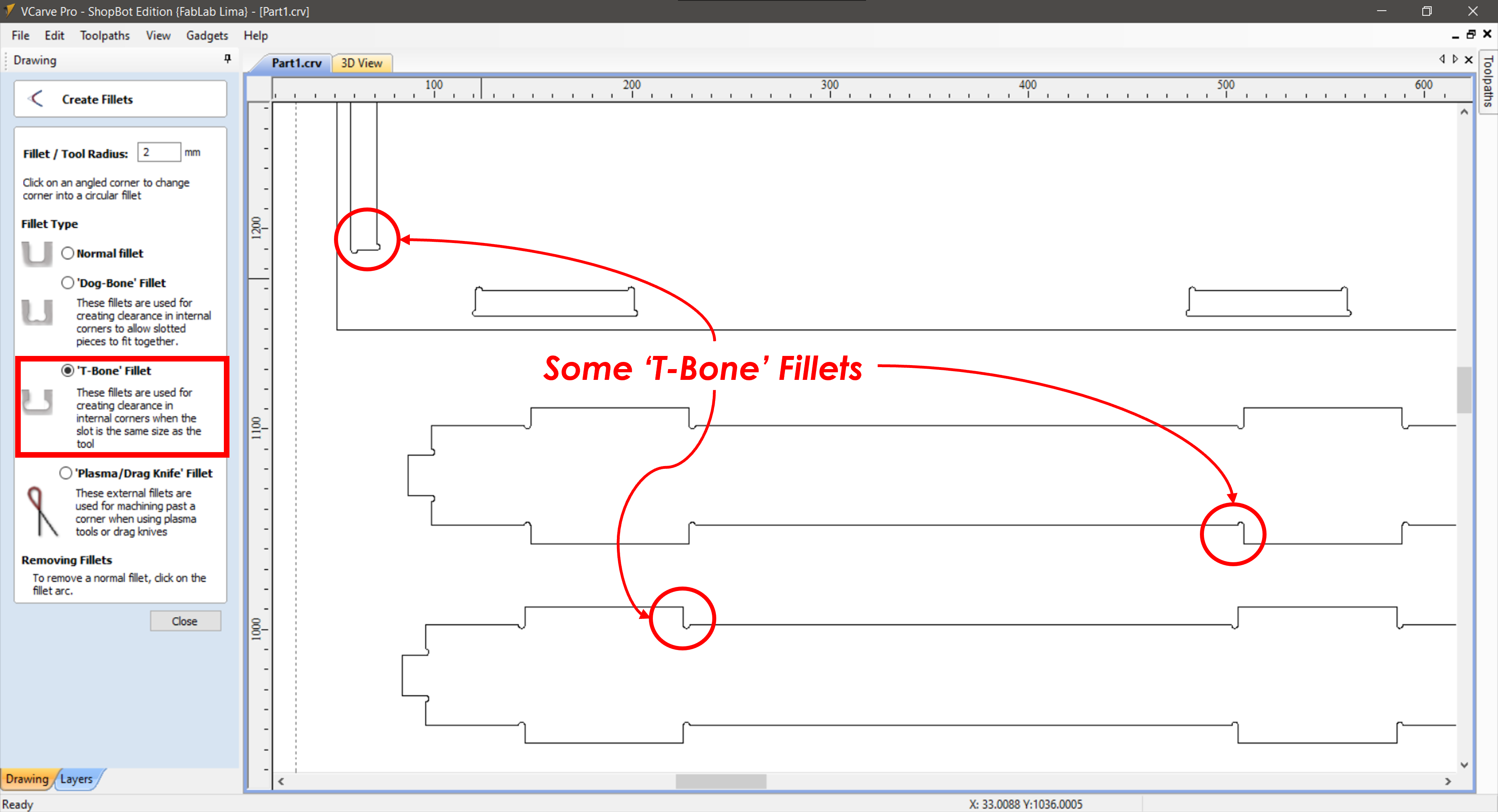
Once the pieces were placed, I checked for any open vectors before moving on. The next step was adding T-Bone fillets at the corners where the bit would struggle to reach. A CNC router uses a circular bit, which means it physically can't cut a perfectly sharp interior corner — it always leaves a radius. T-Bone fillets solve this by adding a small circular relief cut at each corner, allowing mating pieces to fit together properly without interference.
With the fillets in place, I generated the toolpaths. The order matters: pocket first, then internal cuts, then external cuts — this way the pieces stay secured to the sheet until the very last pass. Tabs were also added for extra security. For the second part, an additional pocket toolpath for the LED channels was included.
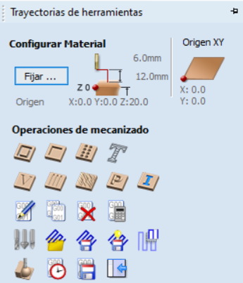
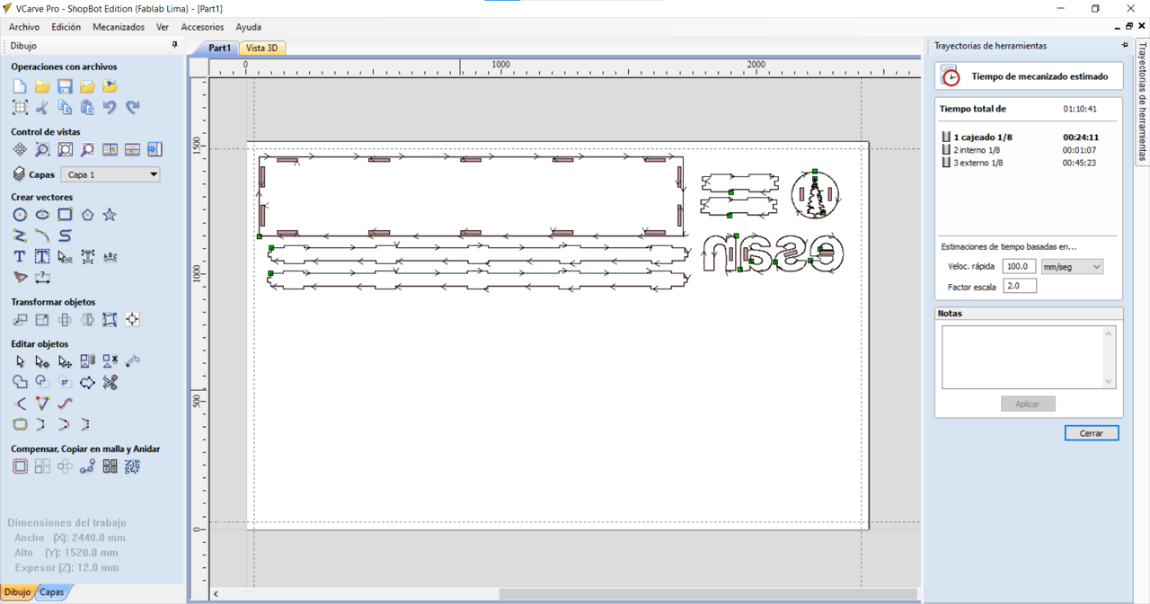
The work was split into three parts:
Part 1 — box pieces and board structure
- Pocket → 24 min 11 sec
- Internal profile → 1 min 7 sec
- External profile → 45 min 23 sec
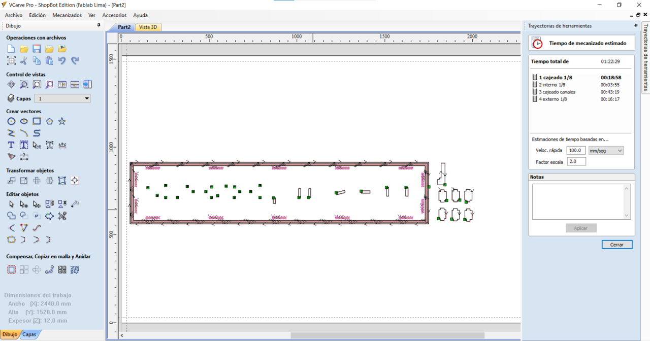
Part 2 — main board with LED channels
- Pocket → 18 min 58 sec
- Internal profile → 3 min 55 sec
- Pocket — LED channels → 43 min 19 sec
- External profile → 16 min 17 sec
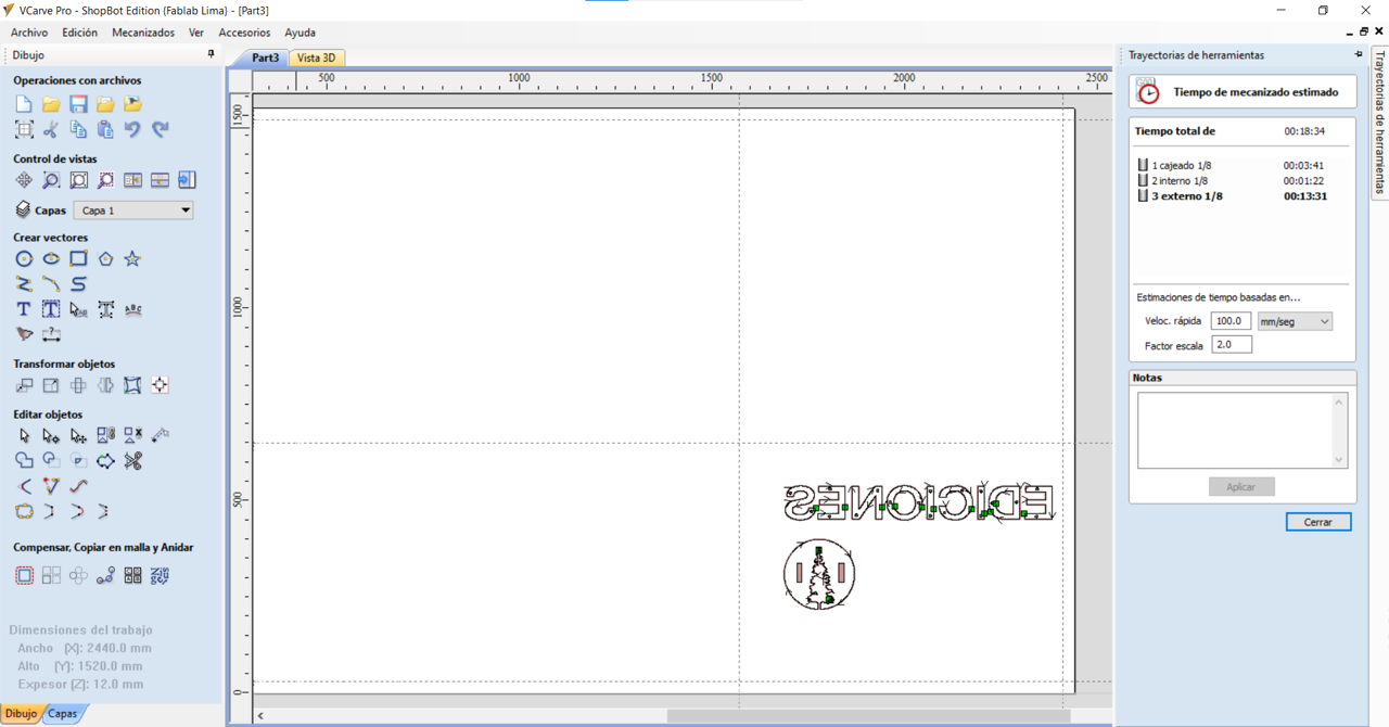
Part 3 — letters and logo
- Pocket → 3 min 41 sec
- Internal profile → 1 min 22 sec
- External profile → 13 min 31 sec
Note: The pocket depth for the press-fit joints was set to 9mm, while the LED channel pocket was set to 5mm — just enough depth to house the LED strip without cutting through the board.
For the individual project, I used the 1/8" Straight End Mill (13728) for all toolpaths — a finer bit chosen to capture the level of detail in the letters and logo. Compared to the 1/4" Down-cut used in the group assignment, this bit required a lower feed rate to avoid breakage. The parameters used were the default values from VCarve Pro's tool database. Finally, VCarve Pro's 3D preview was used to verify everything looked correct before sending the files to the machine. The total estimated machining time for the entire project was 2 hours, 51 minutes, and 44 seconds.
| Parameter | Value |
|---|---|
| Tool | 1/8" Straight End Mill (13728) |
| Flutes | 3 |
| Spindle Speed | 14,000 RPM |
| Feed Rate | 2.0 in/sec |
| Plunge Rate | 1.0 in/sec |
| Pass Depth | 0.125 in |
| Stepover | 50% (0.0625 in) — default value |
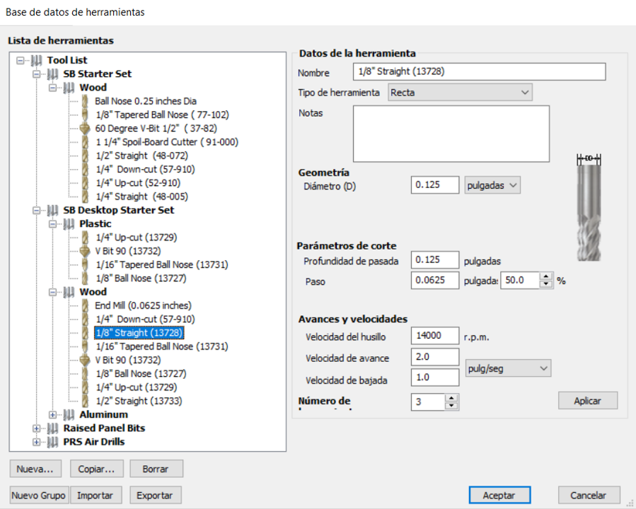
📝 Note: The chipload was not calculated manually — all parameters were taken directly from VCarve Pro's built-in tool database. The 50% stepover was the default value for this tool; a smaller stepover could have reduced the number of passes and total machining time, but since this was a first run with this bit, the default was kept as a safe starting point.
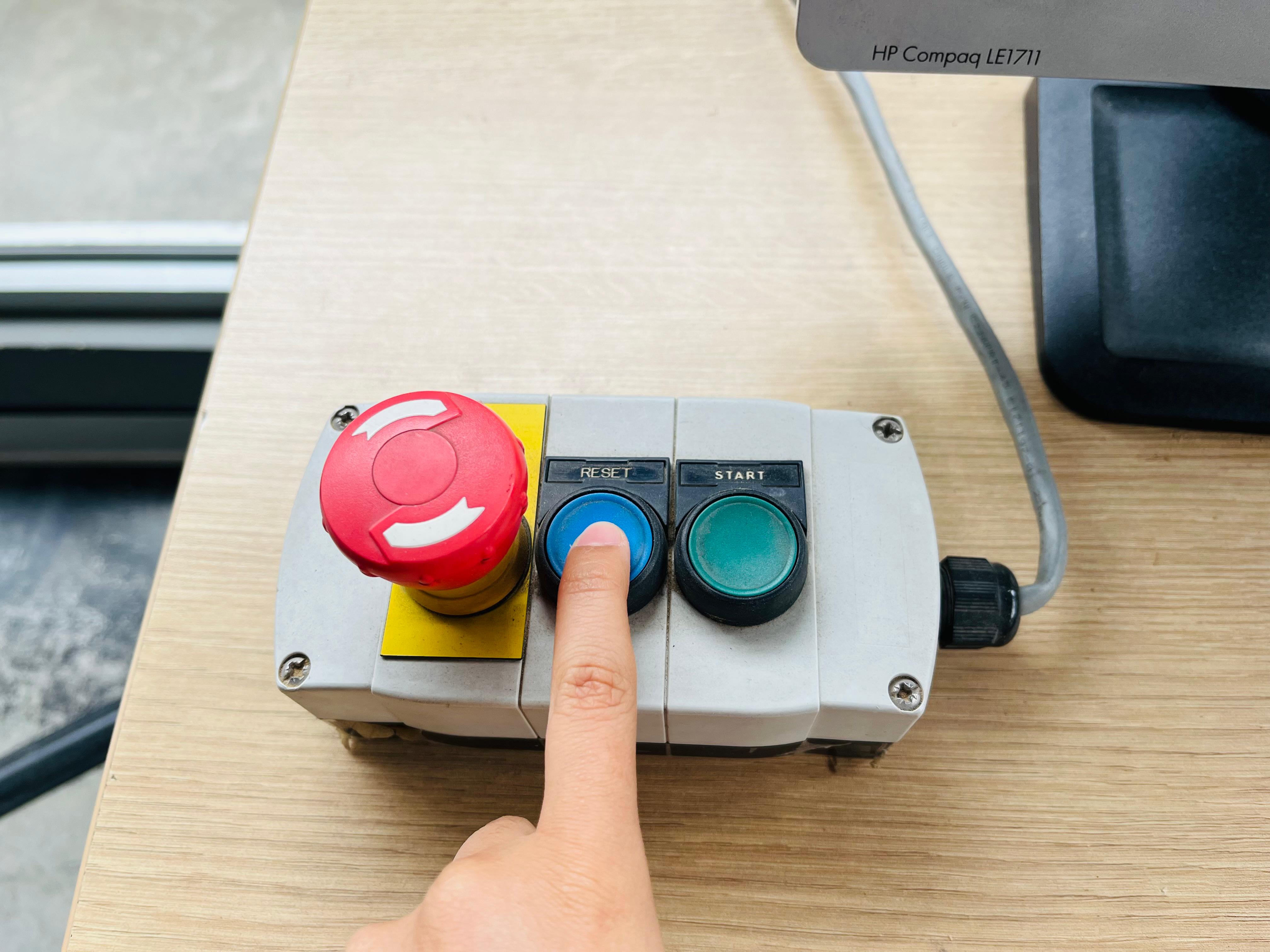
To start, I turned on the machine and opened the ShopBot CNC software, which automatically prompted me to press the reset button to initialize the controller. Then I loaded the corresponding file for the first block.
📝 Note: The exact version of the ShopBot CNC software is unknown — the lab's computer cannot be updated, as newer versions are incompatible with the current Windows 10 installation, and upgrading to Windows 11 carries the same risk.
Milling
Before starting the machine, the first step was to secure the MDF sheet to the machine bed using wood screws, ensuring it wouldn't move during the milling process. I also verified that the correct bit was installed — the 1/8" Straight End Mill (13728).
To start, I turned on the machine and opened the ShopBot CNC software, which automatically prompted me to press the reset button to initialize the controller. Then I loaded the corresponding file for the first block.
Before running each block, the machine had to be calibrated. Since the MDF sheet can sometimes be slightly warped, I calibrated at the center of the working area for each block rather than just once. The calibration process was:
1. Z-axis Calibration
Using the Z Zero Plate, a metal plate placed directly under the bit, connected via an alligator clip. The software automatically lowers the bit until it touches the plate, detecting the exact surface height. Once done, the software displays an alert reminding you to remove the alligator clip and put away the plate before continuing — a key safety step.
2. X and Y Axis Calibration
Setting the origin point for the horizontal plane, ensuring the machine knows exactly where to start cutting on the X and Y axes.
Once calibrated, I loaded the file and clicked Cut Part. The software then prompted me to turn on the spindle — on this machine, spindle control works through both the software and the machine itself: the software displays an alert, you press the physical Start button on the machine, and then confirm in the software — and the milling began.
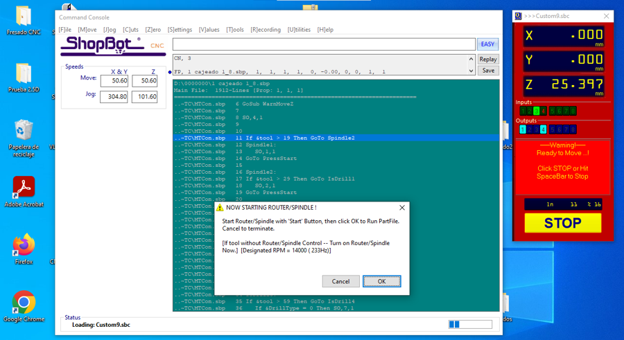
Note: This entire process — calibration, file loading, and cutting — was repeated for each of the three blocks, always following the correct order of toolpaths.
Between each block, I took the opportunity to vacuum the sawdust generated during milling to prevent any buildup that could interfere with the next cuts. I also removed the pieces that were already loose, checking that each cut was clean — the tabs helped keep everything in place, so anything still well-secured stayed on the sheet. For the pieces that were harder to reach, I had to climb onto the machine bed to extract them — always with the machine off, of course.
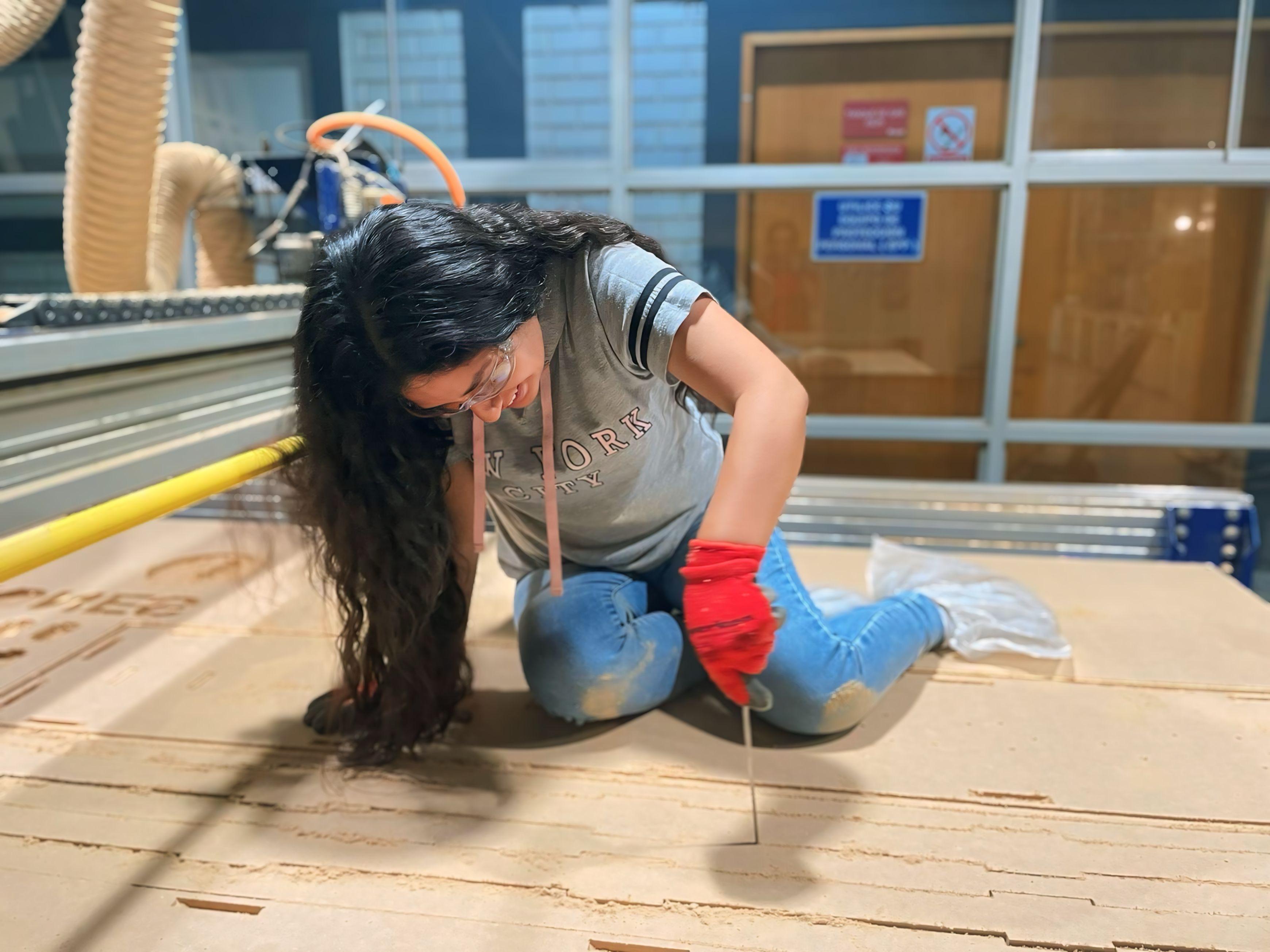
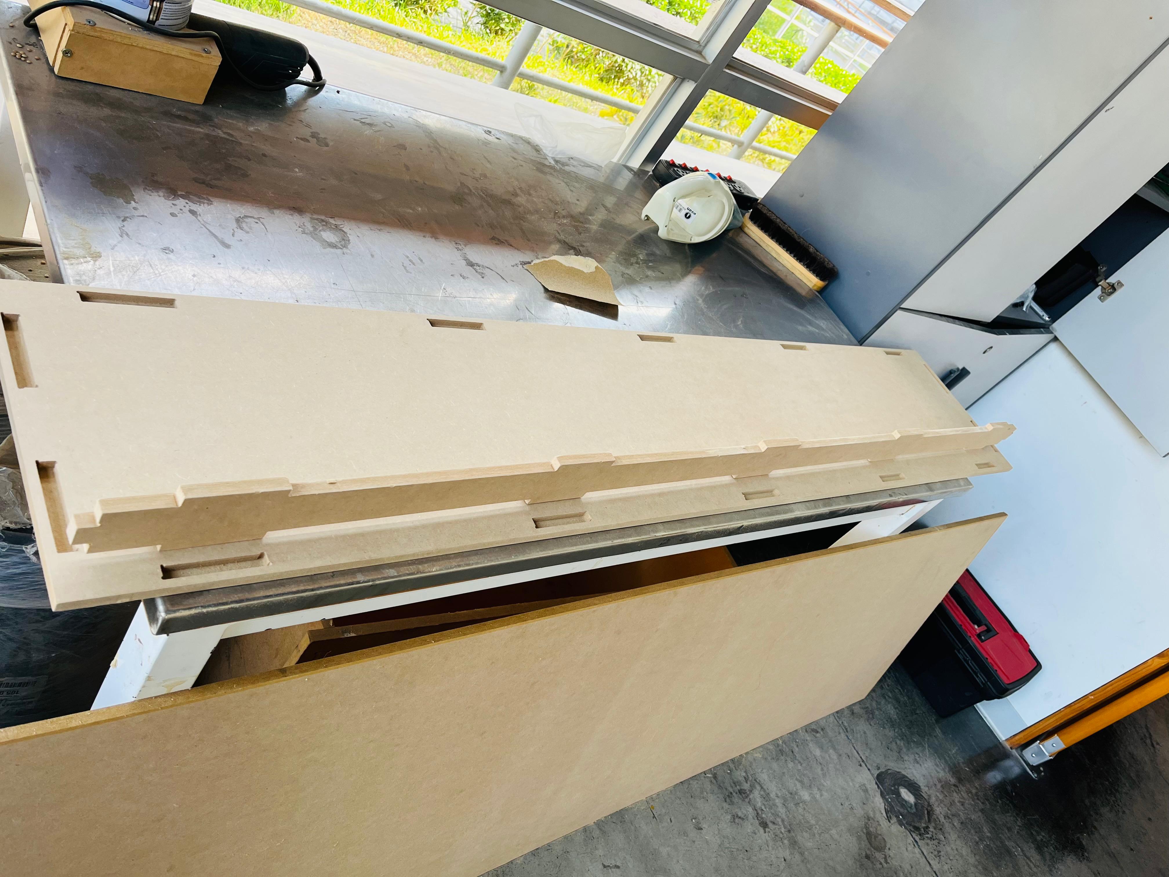
Once all pieces were removed, each one was sanded individually to smooth out the edges and remove any excess material. After sanding, it was time to do a test assembly to verify that the tolerances were correct and that everything fit together properly and securely.
Assembling
With all pieces sanded, it was time to assemble. The back box came together like a rectangular frame: the longer slats ran along the length of the board, and the shorter ones across the width. The joints fit smoothly into their corresponding slots — no forcing required, the press-fit worked exactly as designed.
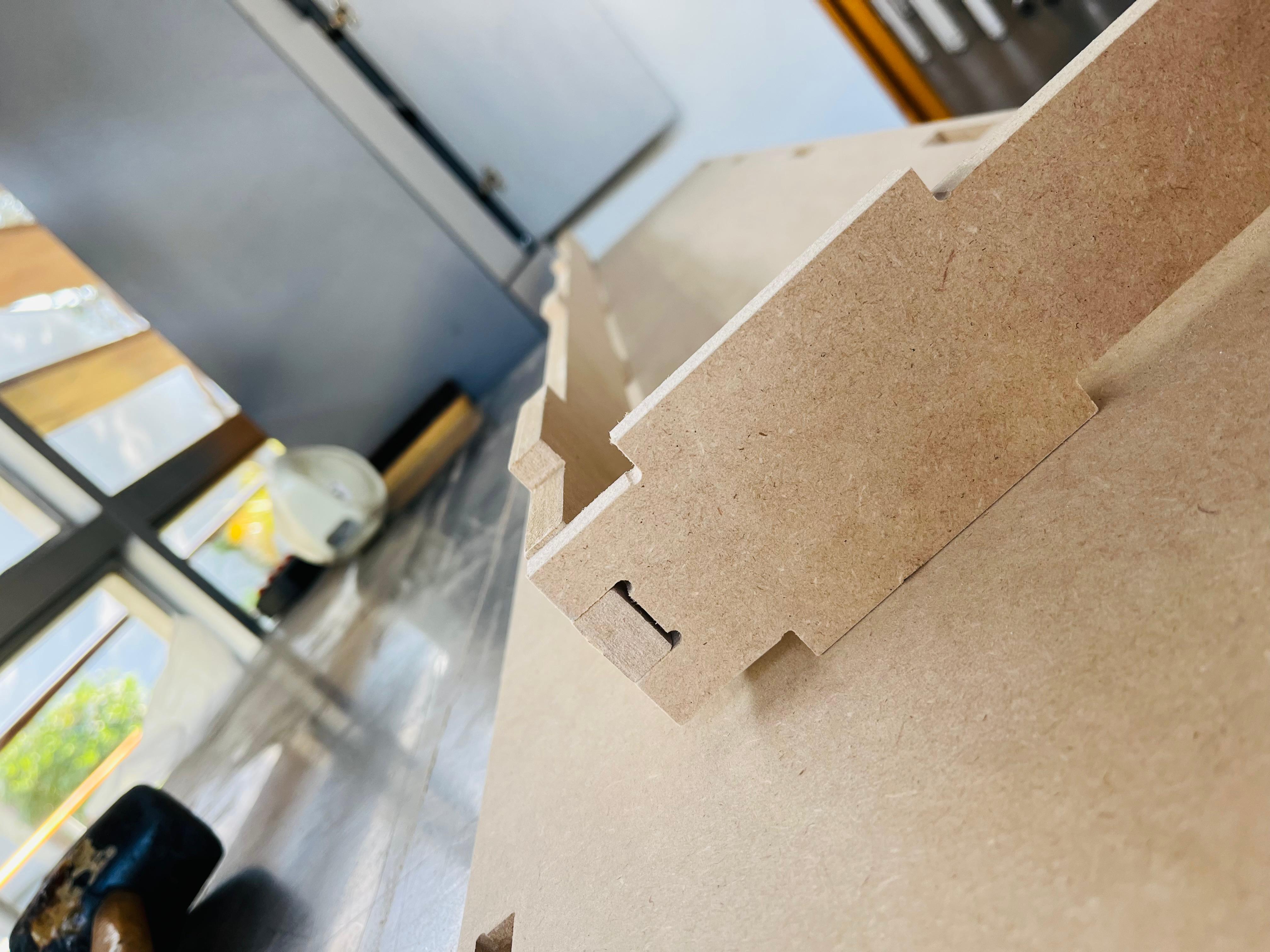
The letters, each with their connectors, also fit perfectly into the cuts on the front board. One important design detail: the connectors had a deliberate height difference between the board and the letters, creating a gap that would allow light to escape around the contour of each letter once the LED strips were installed.
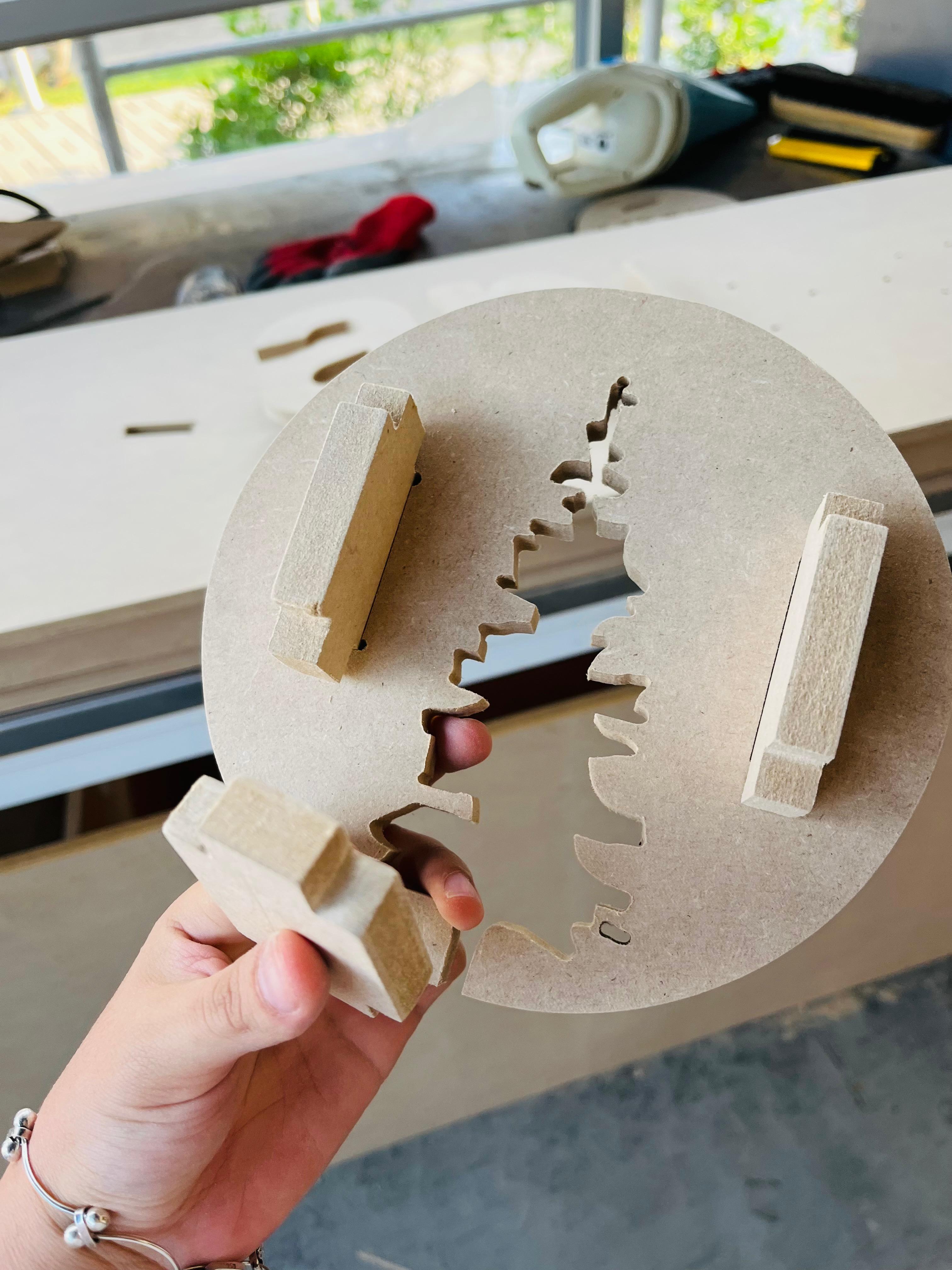
Since MDF tends to warp with humidity, once the sign was in its final installation position it was reinforced with wood glue for long-term safety — but during the dry assembly, the press-fits held everything together without any additional fasteners. The electrical work — painting, wiring, and installation — was handled by the infrastructure team, who collaborated on bringing the final piece to life.
⚠️ Problems & How I Fixed Them
The main issue came up during the milling of the last block — the letters. Some small pieces didn't come out cleanly because of the tab placement: the tabs were positioned in areas that left visible marks on the letter edges, affecting the final shape.
| Problem | What happened | How I fixed it |
|---|---|---|
| Tab marks on curved sections | Tabs placed on curved edges left visible marks that couldn't be fully recovered by sanding, affecting the letter shape | No full fix was possible — the curve geometry made it impossible to sand cleanly without altering the shape |
| Tab marks on straight sections | Tabs on straight edges also left marks, but the impact on the final shape was minimal | Sanding smoothed out the mark cleanly without affecting the letter's form |
💡 For future cuts, the solution is straightforward — reposition the tabs on straight edges from the start, avoiding curves entirely.
Hero Shot 🏆
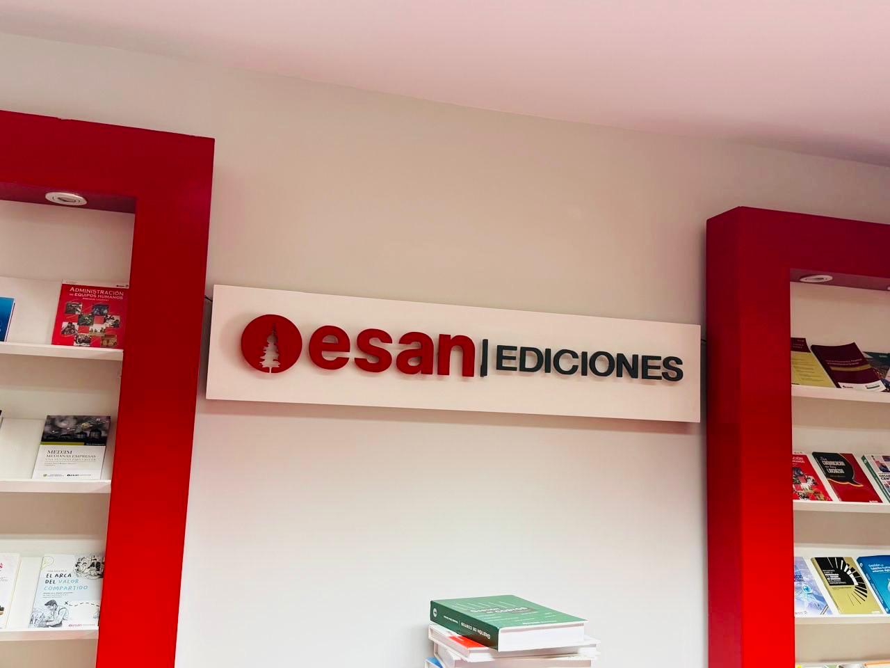
The sign installed in its final location — off.
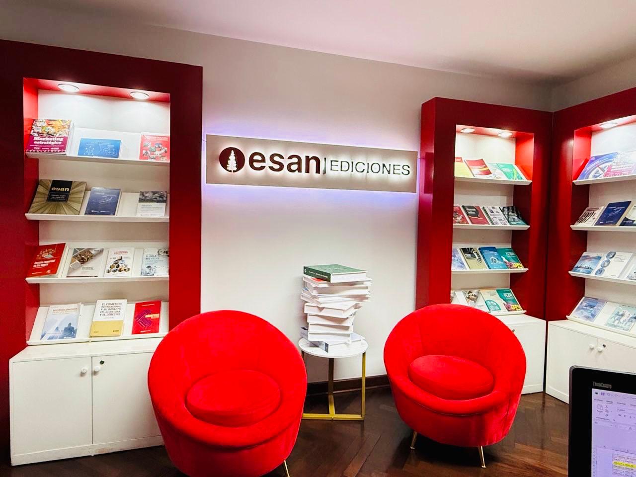
And just like that, the whole thing lights up! ✨ The LED strips bring each letter to life, illuminating the contours and the base of the sign.
Final Thought
As part of the 2025 cycle, I designed and fabricated the sign — from the CAD model to the milled and assembled piece. In 2026, returning to complete the documentation, I finally got to see the finished result: painted, lit, and installed in its final location. It was the first time I saw it complete, and it was worth the wait.