
W3 | Computer-Controlled Cutting
📝 Group Assignment:
- Do your lab's safety training.
- Characterize your lasercutter's focus, power, speed, rate, kerf, joint clearance and types.
What We Did
This week, as part of the group assignment, we covered two main topics: lab safety training and laser cutter characterization. During the safety session, we reviewed the essential procedures and good practices required before operating any laser cutting equipment in the lab. For the characterization, we evaluated the TROTEC Speedy 400 CO₂ laser cutter.
What I Learned
⚠️ Safety
The safety training highlighted that several practices, although they may seem routine, are essential for safe machine operation. Wearing protective goggles helps prevent long-term eye damage from scattered laser radiation. It is also important to wait for the fume extraction system to clear the smoke before opening the machine, rather than inhaling the fumes generated during cutting. The most important lesson was to never leave the laser cutter unattended while it is operating, so that any unexpected situation can be addressed immediately using the emergency stop button.
💡 Characterization
From the characterization process, I learned how practical the TROTEC Speedy 400 Job Control profiles are. Having pre-configured settings for different materials and operations simplifies the workflow. I also gained a better understanding of the importance of kerf testing. Although the kerf is only a fraction of a millimeter, it can significantly affect how well the final parts fit together.
To see the full process in detail — you can visit the folowing page here.
📝 Individual Assignment:
- Design, lasercut, and document a parametric construction kit, accounting for the lasercutter kerf, which can be assembled in multiple ways.
- Cut something on the vinyl cutter.
Parametric Construction Kit
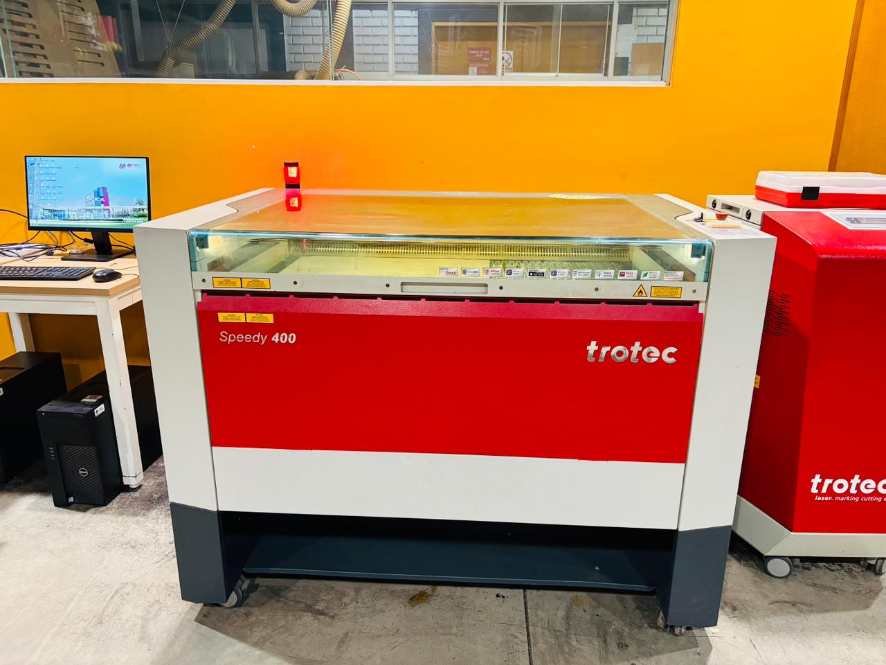
TROTEC Speedy 400
What is a Parametric Construction Kit?
A parametric construction kit is a set of pieces designed with variable parameters that control their dimensions and geometry. When a value is modified, every part of the design that depends on that parameter updates automatically — making it possible to scale, adapt, or adjust the pieces without redrawing them from scratch.
Kit Overview
For this assignment, I designed a press-fit construction kit in Autodesk Fusion. The kit consists of four pieces, all derived from a shared parameter set. Each piece has rectangular and triangular slots that allow them to connect and stay together without adhesives, and can be assembled in multiple configurations.
The design process started by defining a set of user parameters directly in Fusion's parameter manager. Instead of entering fixed dimensions into the sketch, each measurement is linked to a named parameter — so adjusting a single value is automatically updated through the entire geometry. This approach makes it straightforward to test different slot sizes, tolerances, or proportions without modifying the sketch manually.
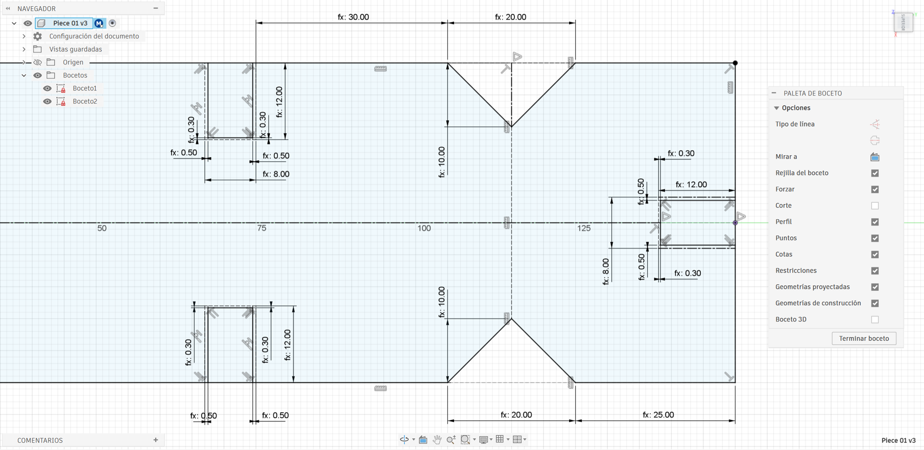
Base Parameters
All pieces share a common set of user parameters defined in Fusion 360. These parameters control the overall dimensions of each piece as well as the size and position of the slots:
| Parameter | Description |
|---|---|
| Ll | Total length of the piece |
| Hh | Height of the piece |
| Cl | Width of the rectangular slot |
| Cd | Depth of the rectangular slot |
| Ul | Left-side tolerance |
| Ud | Right-side tolerance |
| Mn | Width of the triangular slot |
| Dd | Height of the triangular slot |
| Rr | Distance from the edge to the triangular slot |
| Jj | Distance between the rectangular and triangular slots |
| e | Piece thickness |
The Four Pieces
The kit includes four pieces, each sharing the same base parameters but differing in their shape and slot configuration:
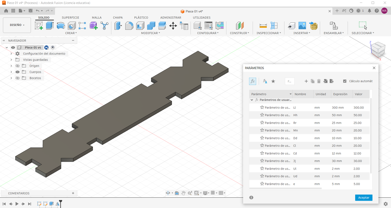
Piece 01
Is the base piece — rectangular in outline, with four slots along its center.
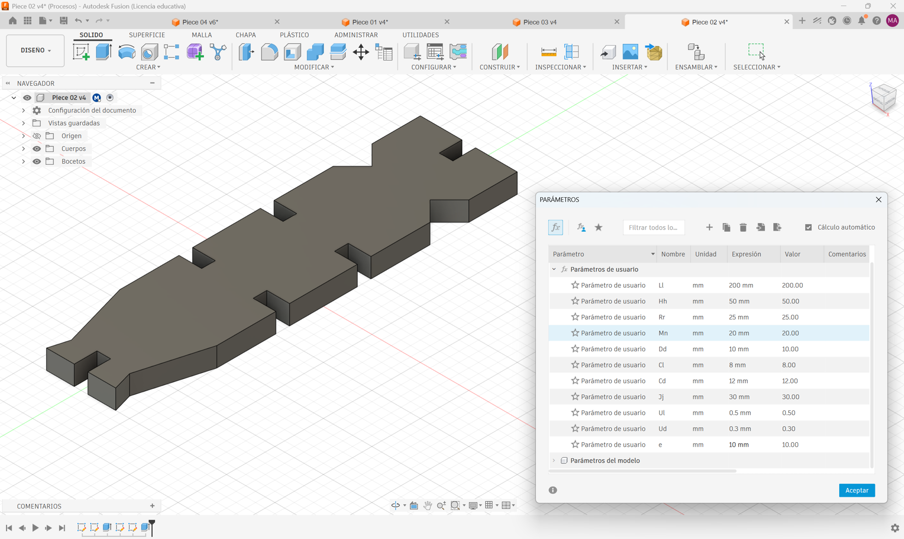
Piece 02
Shares the same slot structure but features one curved side, giving it a different silhouette that adds variety to possible assemblies.
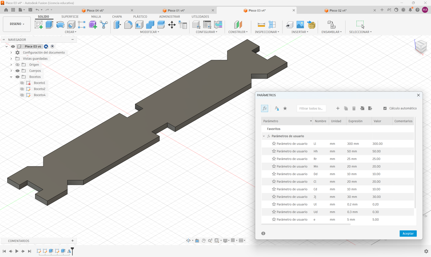
Piece 03
Is also rectangular but includes only two slots along its center, making it a shorter connector between pieces.
Piece 04
Is the most distinctive piece of the kit. Instead of a solid body, it features a repeating cut pattern along its length that gives the piece flexibility — the more repetitions, the more flexible the piece becomes.
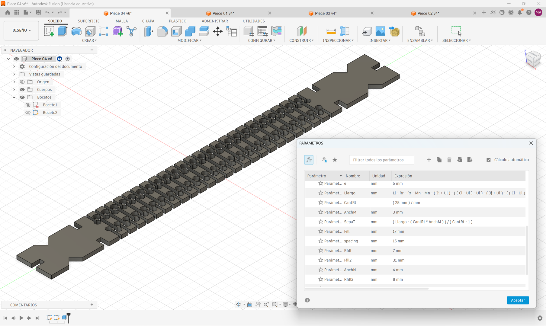
Piece 04 — Flexibility
Piece 04 introduces an additional parameter called CantRt, which controls the number of cut repetitions along the piece. This parameter is calculated from the total usable length and defines how many segments are distributed evenly across the body. The higher the value, the greater the flexibility of the piece — allowing it to bend when assembled, which opens up curved and non-linear configurations that the other pieces cannot achieve.
Pre-Cut Setup
1 Kerf Test
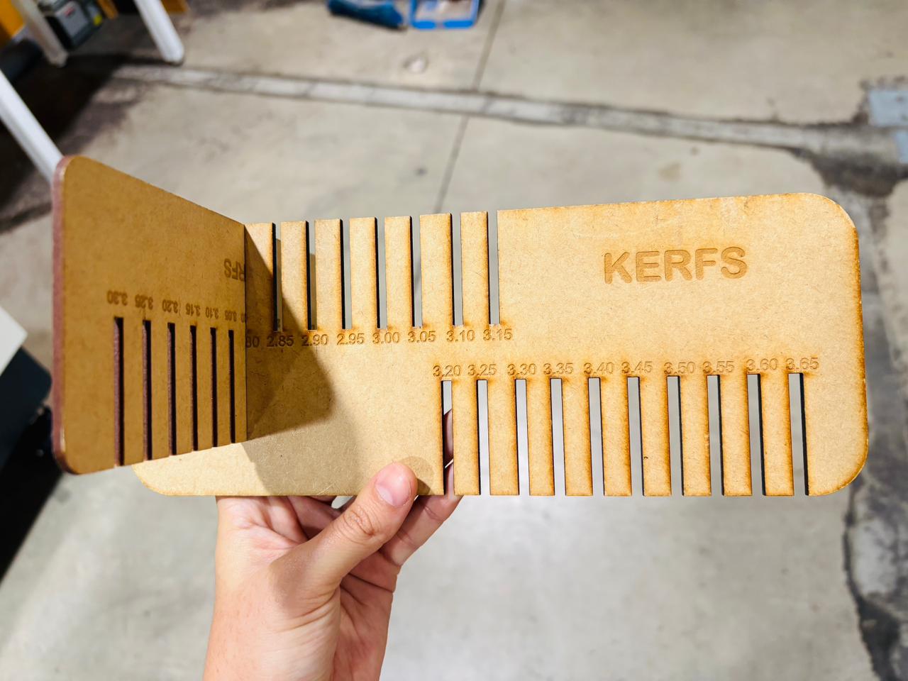
Before cutting, I used a kerf test available in the lab — fabricated from the same 3mm MDF material I would be using for my kit. This comb-style tool has slots at incremental widths, and by sliding the pieces together I was able to identify which slot produced a snug, accurate fit. The result confirmed a kerf value of 0.2mm for this material and machine combination.
2 Applying the Kerf to the Design
With the kerf value defined, I updated the Ul and Ud tolerance parameters in Autodesk Fusion. This ensures that all slot widths across the four pieces account for the material removed by the laser, resulting in a precise press-fit.
3 Exporting from Fusion 360
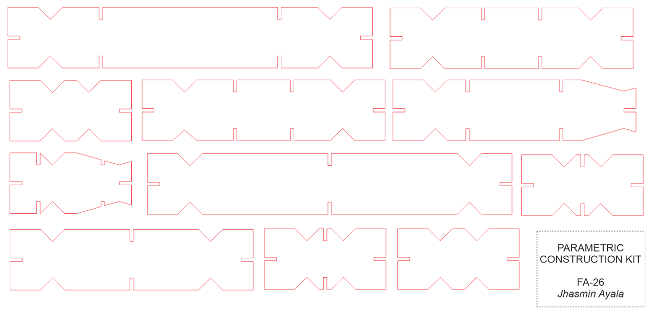
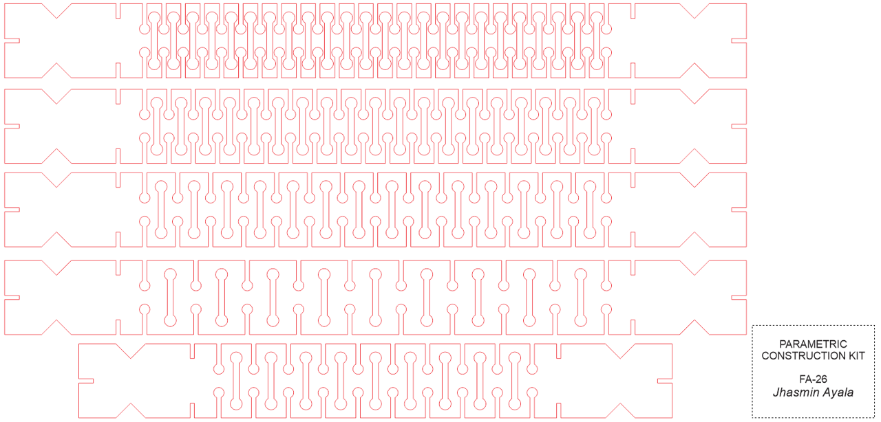
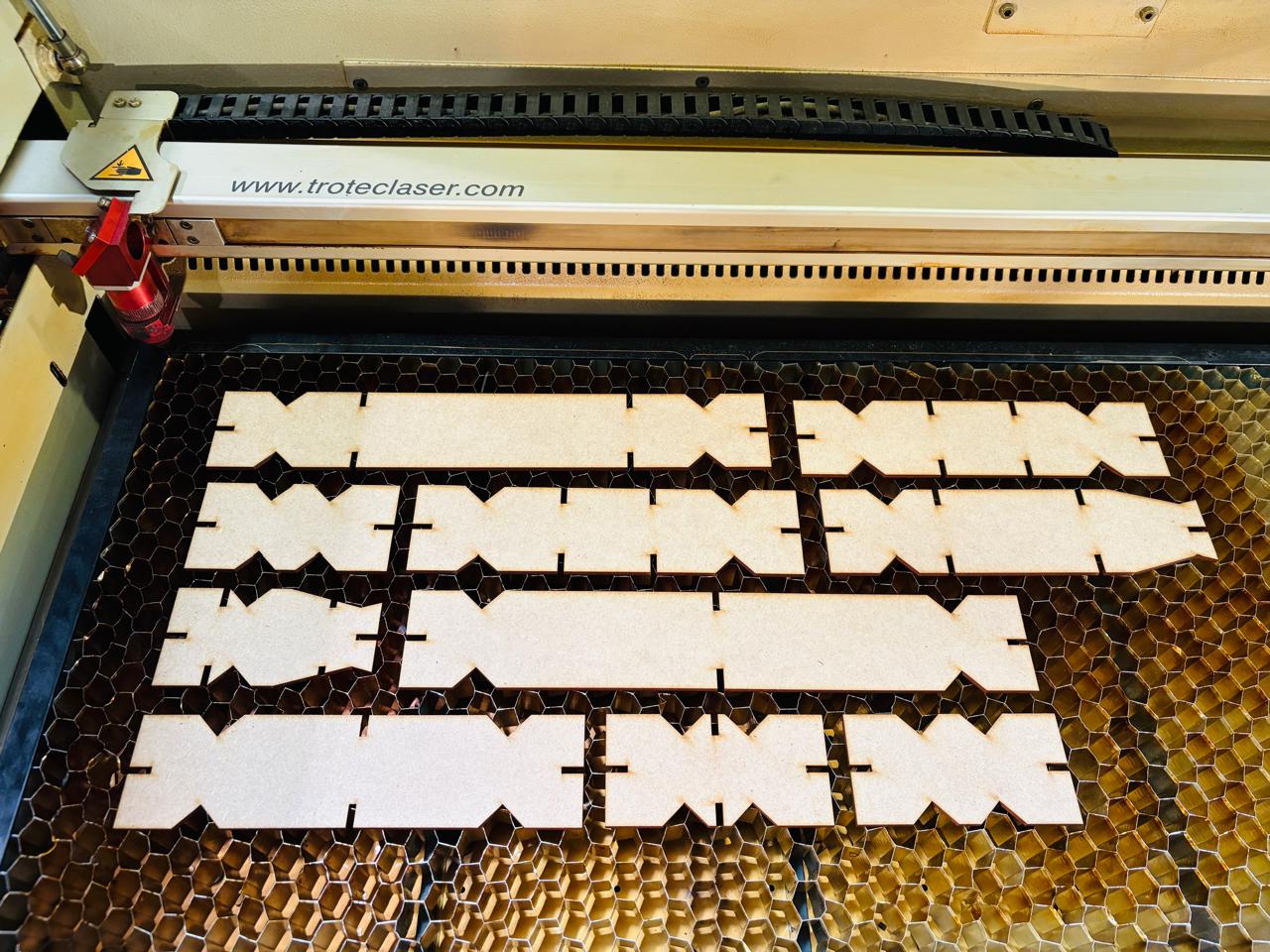
With the kerf applied, I exported the sketches as DXF files. To make the most of the 300 × 600mm MDF sheets available in the lab, I prepared two layouts: one with multiple variations of Piece 04, and a second with variations of Pieces 01, 02, and 03 in different sizes.
4 Design Settings in CorelDraw
With the DXF file open in CorelDraw, I assigned the correct line properties to each path: cut lines were set to red hairline, and engraving lines to black. This color convention is what Job Control — the software linked to the TROTEC Speedy 400 — uses to distinguish between operations. Since the lab maintains pre-configured profiles for each material, there is no need to manually adjust power or speed values. Once the file is ready, you simply select the material type — in this case, 3mm MDF — and the machine applies the corresponding settings automatically. It is worth noting that these pre-configured profiles are not fixed — they can be modified or expanded if you want to test different speed or power settings, or experiment with engraving depth and quality.
| Line | Operation |
|---|---|
| Red hairline | Cut |
| Black | Engrave |

Note: These pre-configured profiles are not fixed and can be modified or expanded to optimize cutting and engraving parameters for different materials. This allows users to experiment with laser power, cutting speed, engraving depth, and engraving quality as needed.
Cutting
1 Turning On the Machine
To power on the TROTEC Speedy 400, a key is used to turn the machine on. Once activated, the platform begins to descend and an alarm sounds to indicate the machine is ready to use.
2 Loading the Material
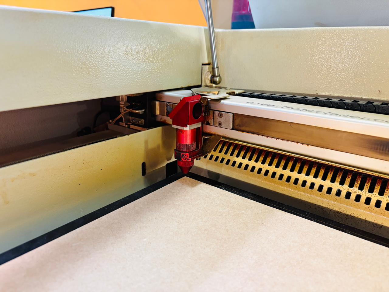
With the cover open, the 3mm MDF sheet is placed in the upper left corner of the cutting bed, which serves as the origin point of the work area (0,0).
3 Calibration
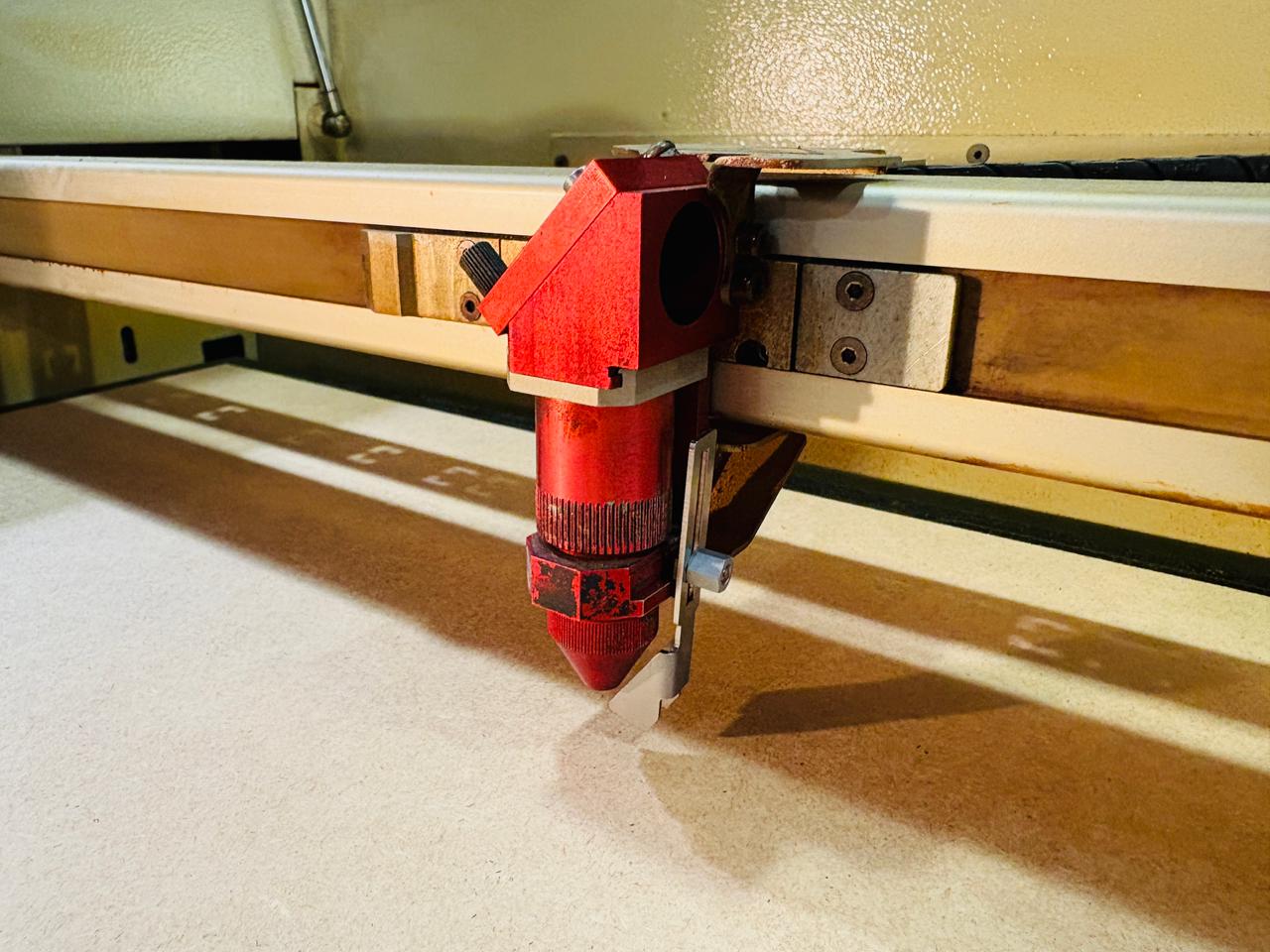
Once the material is in place, the calibration tool is used to set the correct distance between the laser head and the material surface. The tool is inserted into its designated slot on the laser head, and the platform is raised slowly until the tool drops — this is the point at which the correct focal height has been reached. After calibration, the laser pointer is positioned at the upper left corner, establishing the 0,0 origin, and the cover is closed.
4 Sending the File
From the computer connected to the machine, the CorelDraw file is sent using Ctrl+P. The TROTEC cutter is selected as the output device, and in the print settings the material type and sheet dimensions are configured before clicking accept. Job Control opens automatically, where the machine is connected so the job appears in the software. The design is then dragged to the correct position on the virtual cutting bed. Job Control also displays an estimated time for both engraving and cutting, as well as the power and speed settings for each operation.
| Operation | Power | Speed | Frequency |
|---|---|---|---|
| Engrave | 25 | 7.00 | 1000 PPI |
| Cut | 80 | 0.50 | 5000 Hz |
Power: laser intensity (0–100%) · Speed: head movement velocity · Frequency: laser pulse rate (PPI for engraving, Hz for cutting)
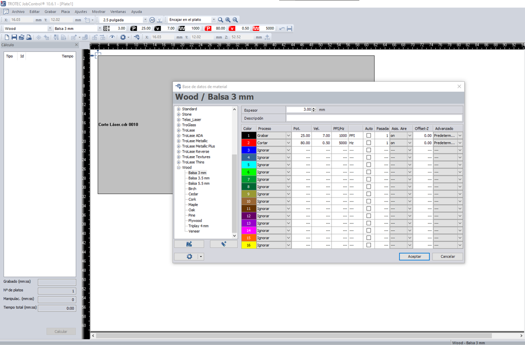
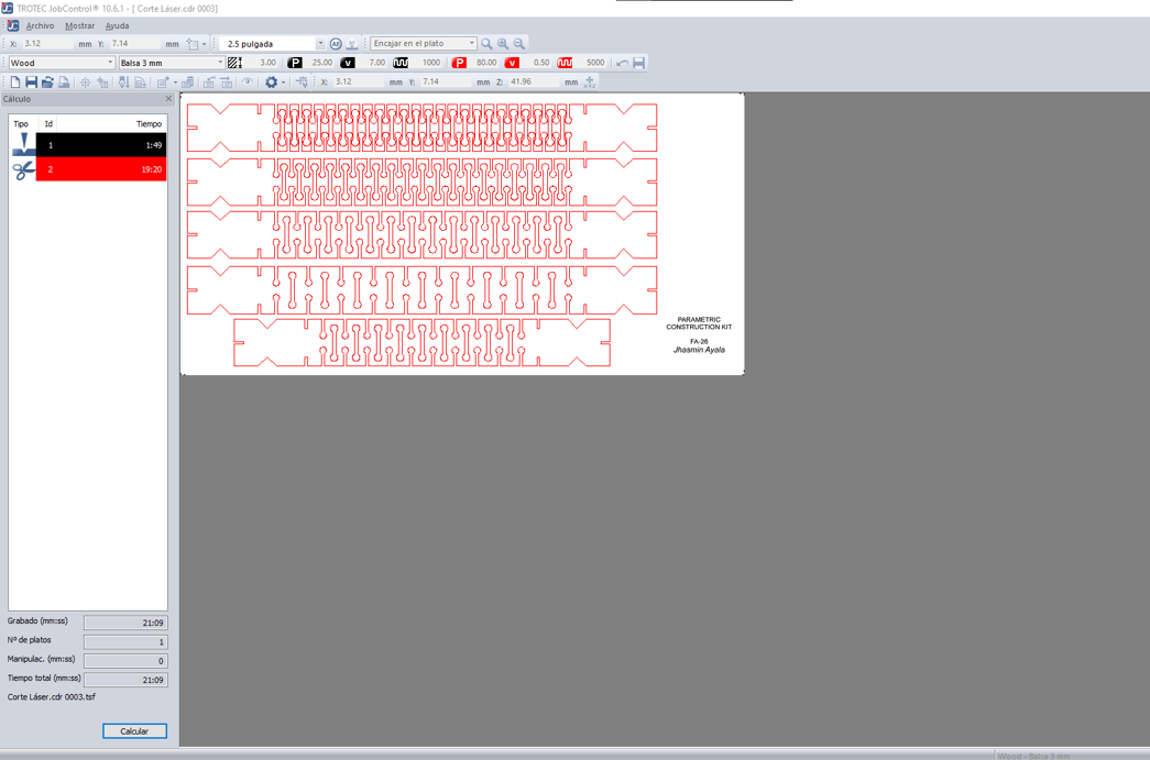
Layout 1 — Piece 04 sheet. Engraving: 1:49 min · Cutting: 19:20 min · Total: 21:09 min.
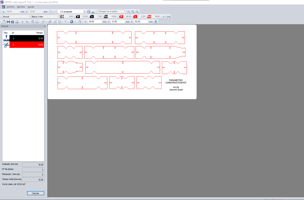
Layout 2 — Pieces 01, 02, and 03 sheet. Engraving: 2:16 min · Cutting: 6:04 min · Total: 8:20 min.
5 Running the Job
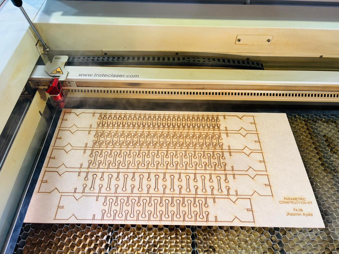
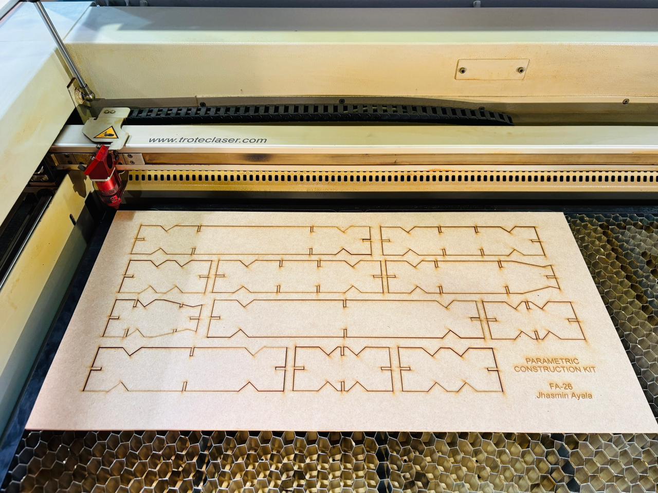
Once everything is verified, the job is started. The machine first completes the engraving pass, then runs the cut. When finished, the machine signals that the job is done. Before opening the cover, it is recommended to wait briefly for the fume extractor to clear any remaining smoke from the cutting area.
6 Removing the Cut Pieces
Once the smoke has cleared, the cover is opened and the pieces are carefully removed from the cutting bed. This same process was repeated for both MDF sheets.
Putting Parametric Flexibility to the Test
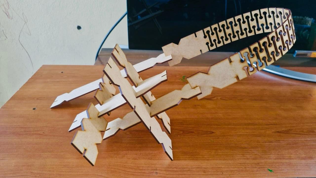
This video shows the flexibility behavior of Piece 04 across different configurations. The more cut repetitions the piece has — controlled by the CantRt parameter — the more flexible it becomes, allowing it to bend smoothly when handled. In contrast, pieces with fewer repetitions show significantly less flexibility, and at the lowest values, the piece can break under the same bending force.
🥳 Hero Shot
With both sheets cut and all pieces removed, the kit was ready to be assembled. The press-fit joints held the pieces together without adhesives, and the flexibility of Piece 04 allowed for curved configurations that added a new dimension to the assembly possibilities. Below, the pieces assembled — showing some of the configurations the kit can achieve.
Vinyl Cutting
Roland GX-24 CAMM-1 Servo
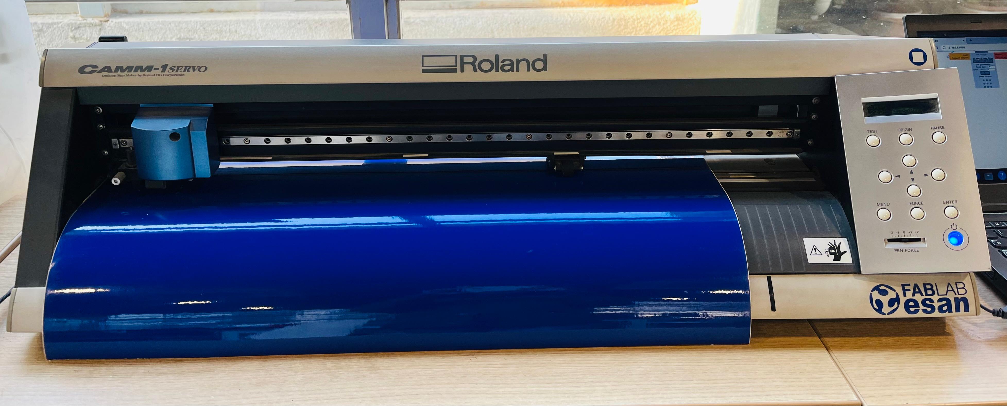
During Week 3, I worked with the Roland GX-24 CAMM-1 Servo, a desktop vinyl cutter used to cut shapes and designs on adhesive materials. With this machine, I cut adhesive vinyl to create custom stickers.
I also explored another application: using the cutter to prepare vinyl masks for sandblasting. This makes it possible to transfer designs onto surfaces such as glass and create engraved patterns.
⚙️ Design Process
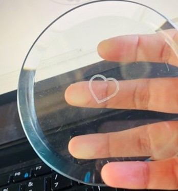
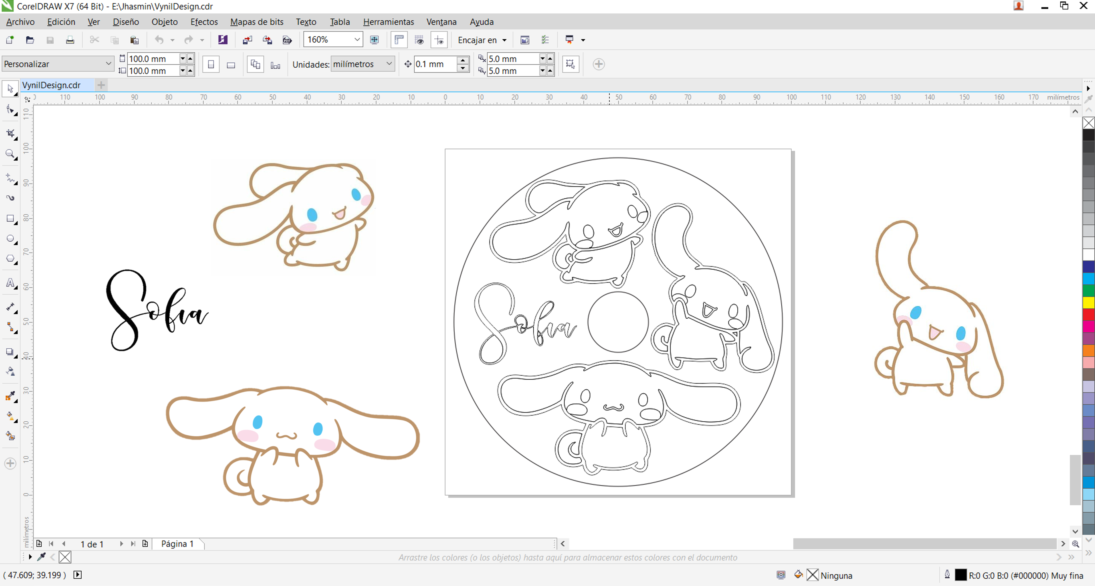
Before starting the vinyl cutting, I first prepared the design. I wanted to try a small sandblasting experiment on a glass coaster, so I measured it to define the area where the vinyl would be placed. While designing, I considered that the uncovered areas would be exposed during the sandblasting process and become engraved.
With this in mind, I developed the design. I chose Cinnamoroll, one of Hello Kitty's characters, and personalized the coaster with my sister's name. I arranged the figures around the border and added the text to fit within the defined area.
For this, I used CorelDRAW, a 2D software that allowed me to vectorize an image, clean unnecessary elements, and prepare the shapes for cutting. Once the design was ready, I exported it in SVG format.
⚙️ Setting Up the Vinyl Cutter Software
-
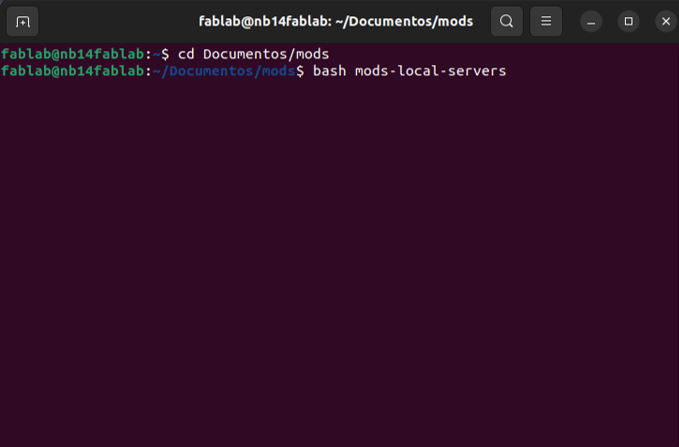
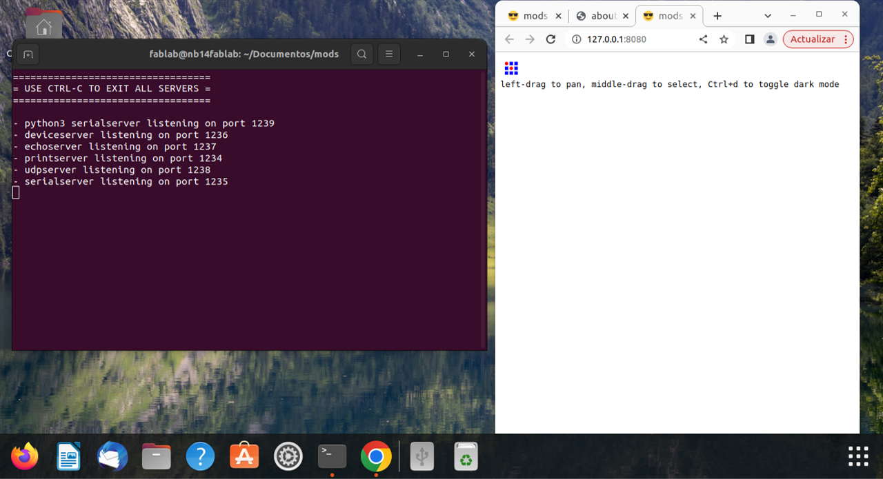
To set up the vinyl cutter, I first connected the Roland GX-24 to the laptop using a serial cable. Once connected, I opened the terminal to launch ModsProject — the program used to generate the toolpaths that the cutter follows — by running the following commands:
$ cd Documentos/mods
$ bash mods-local-server
After pressing Enter, the ModsProject interface opened automatically in the browser. To send the file to the cutter, ModsProject offers two communication modules:
WebUSB
Communicates directly from the browser to the machine via USB, without needing a local server. Works natively in Chrome, which supports WebUSB/WebSerial and can pass through directly to the serial port.
WebSocket pyserial ✓ used
Uses a local server (
mods-local-server) running in the background to bridge the browser with the serial port via a WebSocket connection. This requires the terminal setup shown above.📝 Note: While WebUSB would have worked directly from Chrome without any terminal setup, the lab's Roland GX-24 connects via serial cable — making WebSocket pyserial the appropriate module for this machine's configuration.
- Here are the examples:
-
In ModsProject, the first step is to select the correct machine. In this case, I chose the vinyl cutter module, which allows the program to recognize the Roland GX-24 and generate the appropriate toolpaths for cutting. The workflow of this module is shown in the next image (2).
-
Once the machine is selected, the next step is to add the module that connects the vinyl cutter through the serial port. This enables communication between the computer and the Roland GX-24, allowing the cutting job to be sent once the file is loaded. The complete workflow is shown in image (3).
-
This module must be linked to the workflow generated when the machine is selected. In this step, I also adjusted key cutting parameters such as force and speed. The force controls how much pressure the blade applies, while the speed defines how fast the cutter moves during operation.
🖰 Force: 120 g🖰 Speed: 2 cm/s
For this test, I used a force of 120 g and a speed of 2 cm/s, which provided a clean cut while maintaining good control, especially for smaller details in the design.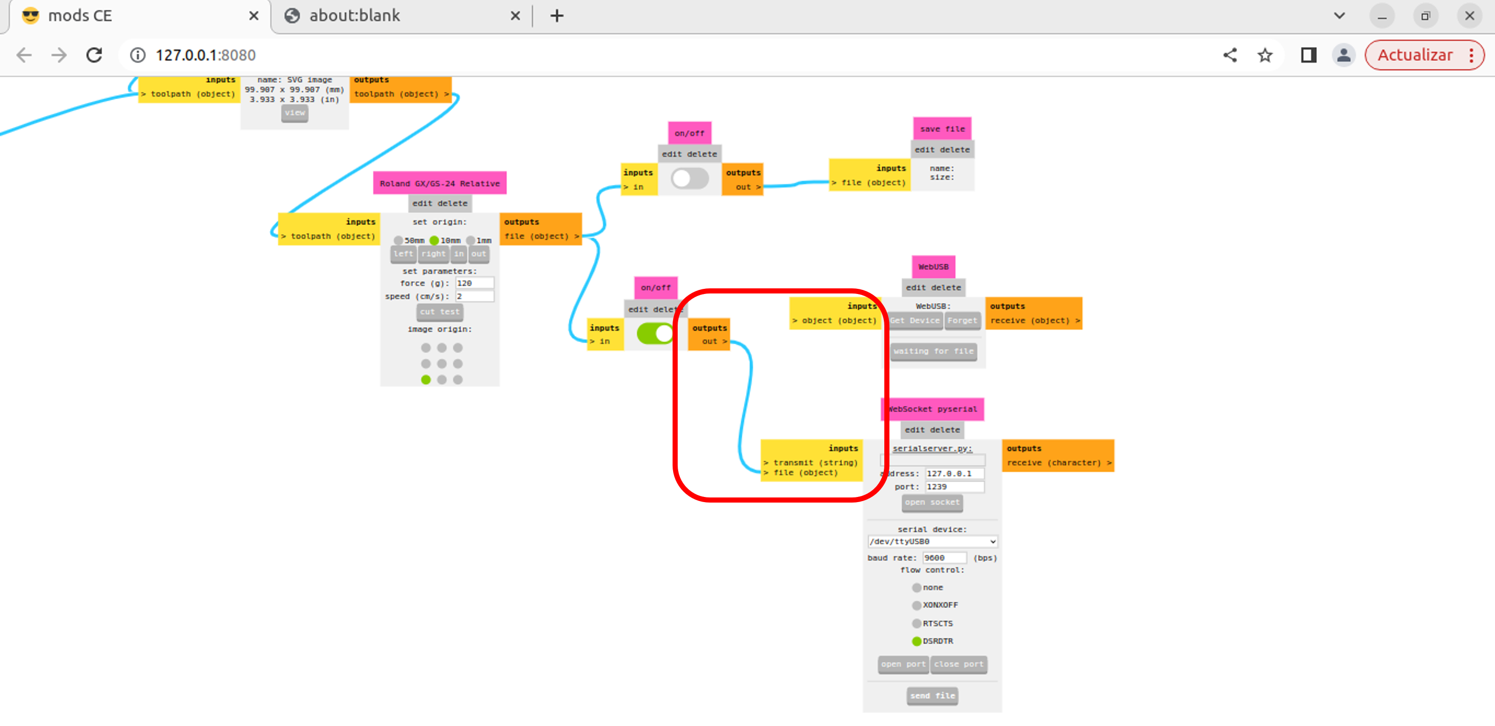
-
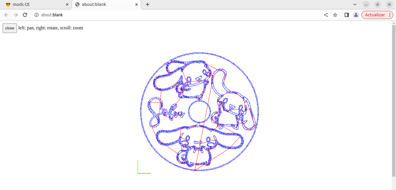
Then, I loaded the SVG file into the workflow and checked both the size and DPI settings. The size is automatically detected once the file is uploaded, but the DPI needs to be adjusted manually so that all cutting paths are correctly displayed in the preview. This step is important to ensure that every line of the design is recognized and ready for cutting.
- Here are the examples:
📝 Note: For this example, I used 150 DPI. When testing other values, the preview did not show the complete toolpaths. This seems to be related to the scale of the design, so the DPI needs to be adjusted according to the file dimensions. This is something I plan to explore further.
🖰 DPI: 150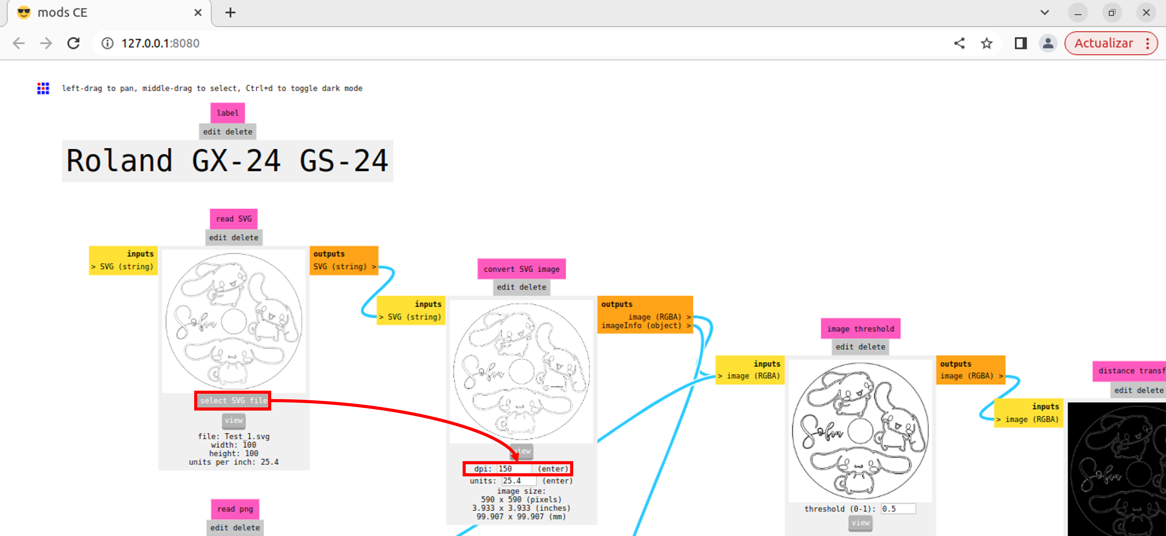
-
Once I confirmed that all the toolpaths were correct and the machine was properly connected to the new module, I sent the file to the vinyl cutter.
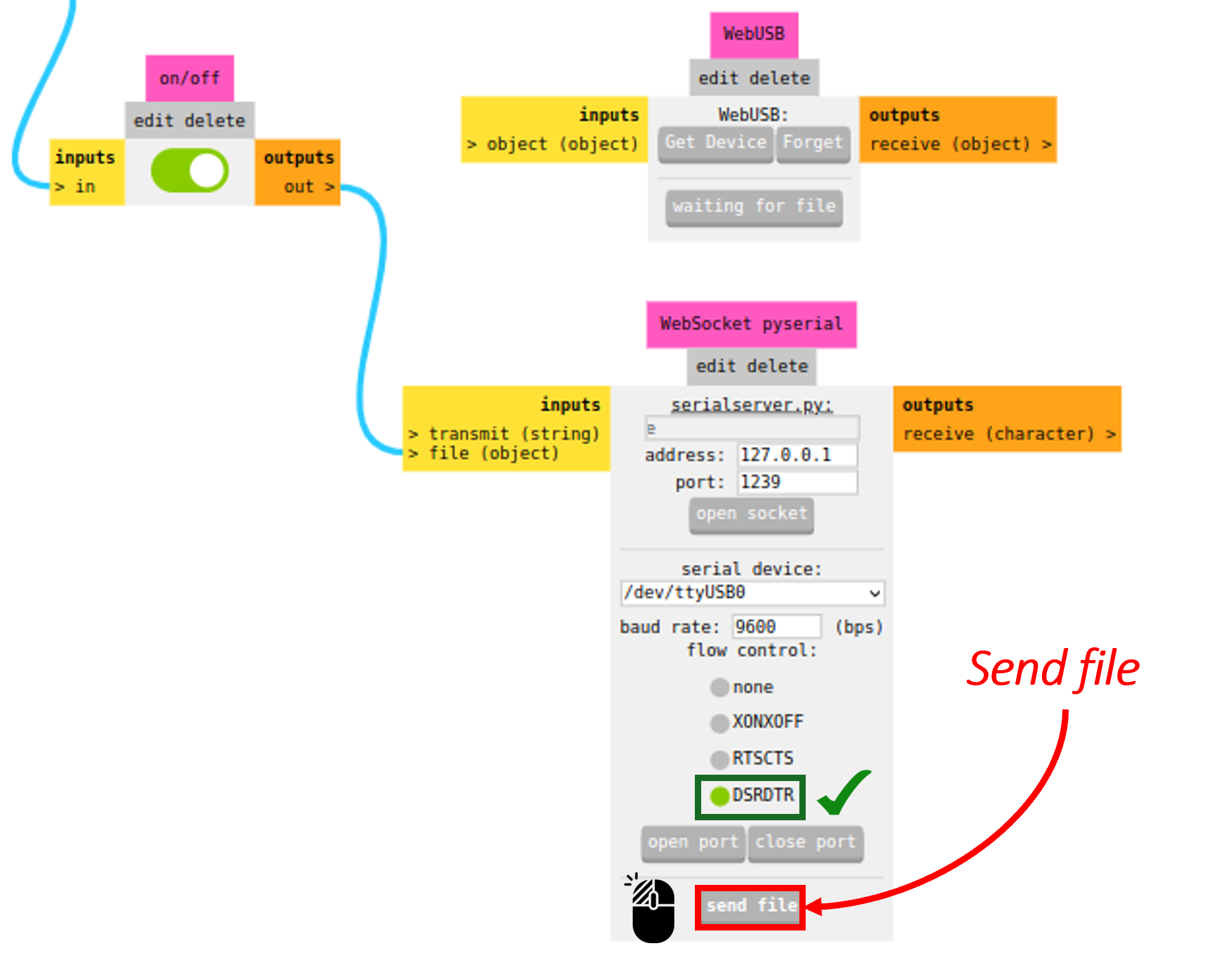

Select the machine (2)
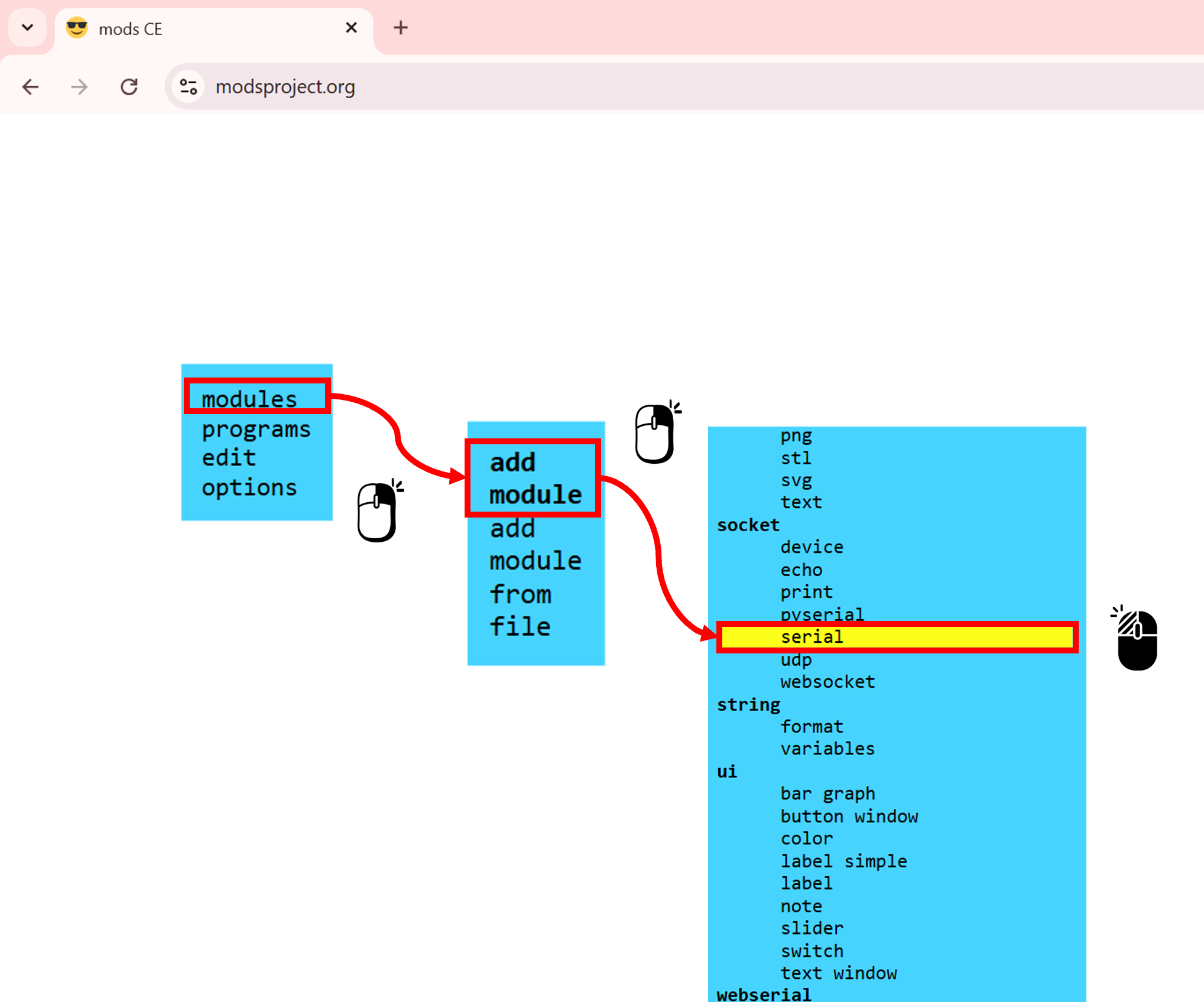
Add the module (3)
⚙️ Setting Up the Vinyl Cutter Machine
-
First, I placed the material, in this case,
blue vinyl. It is loaded from the back of the cutter, where a tray supports it, and inserted from back to front (a), leaving it at the correct height as shown in the image. Then, the material is secured using the lever located on the left side of the machine (b).📝 Note: The cutter has white alignment marks, and the vinyl must be positioned between them to avoid issues during the cutting process (c).
- Here are the examples:
Once the material was properly fixed, I turned on the machine. After powering it on, the cutter automatically measures the length of the material to detect the available working area. This ensures the machine recognizes the limits of the vinyl before starting the cut.
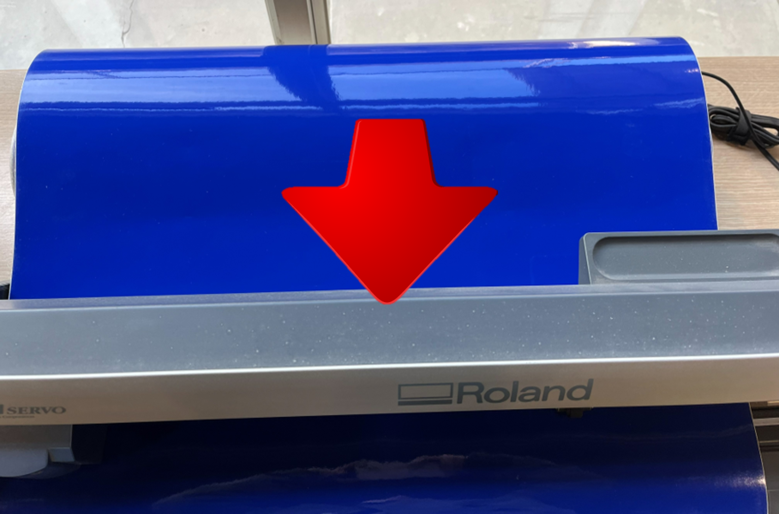
a. Inserting the vinyl into the machine
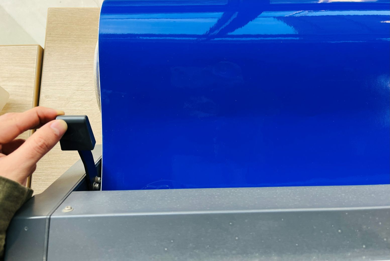
b. Adjusting and securing the material
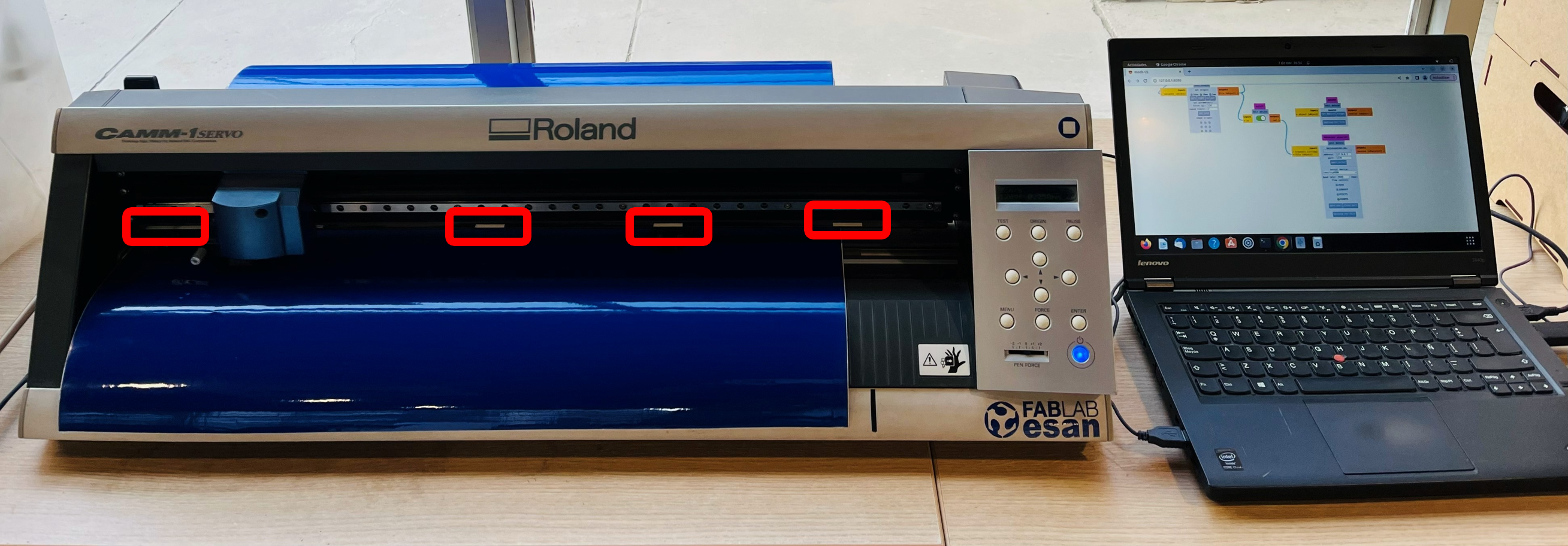
c. Verifying the vinyl position
-
After that, I followed the steps described in the previous section on setting up the vinyl cutter software. Once the file was sent, the machine began the cutting process. The following videos show how the Roland GX-24 performs the cut:
- Watch the video:
📝 Note: In some areas, the vinyl started to slightly lift off the surface during cutting. The exact cause is hard to pinpoint — it could be related to the design itself (broken vector lines or the DPI and size settings used when preparing the file), but it may also be due to the vinyl being old or dried out, or the blade being dull. In practice, it is often a combination of these factors.
- Watch the video:
-
After finishing the cut, I needed to remove the material from the machine. For this, I used a cutter knife to trim it off. The vinyl cutter has a small built-in cutting section that makes this step easier, as shown in the image. And with that, the cutting process was complete — the design was ready for the next steps!
- Here are the examples:
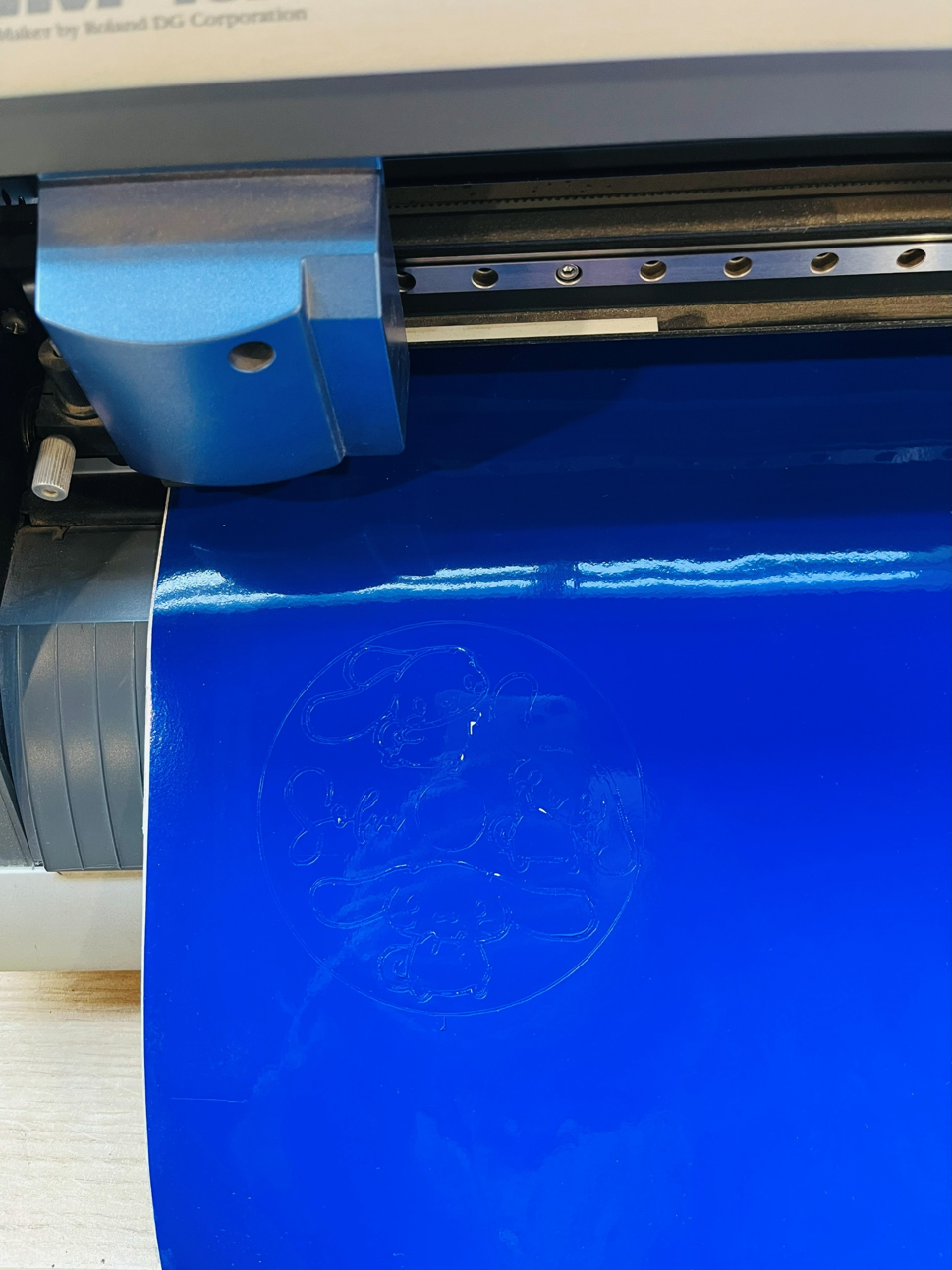
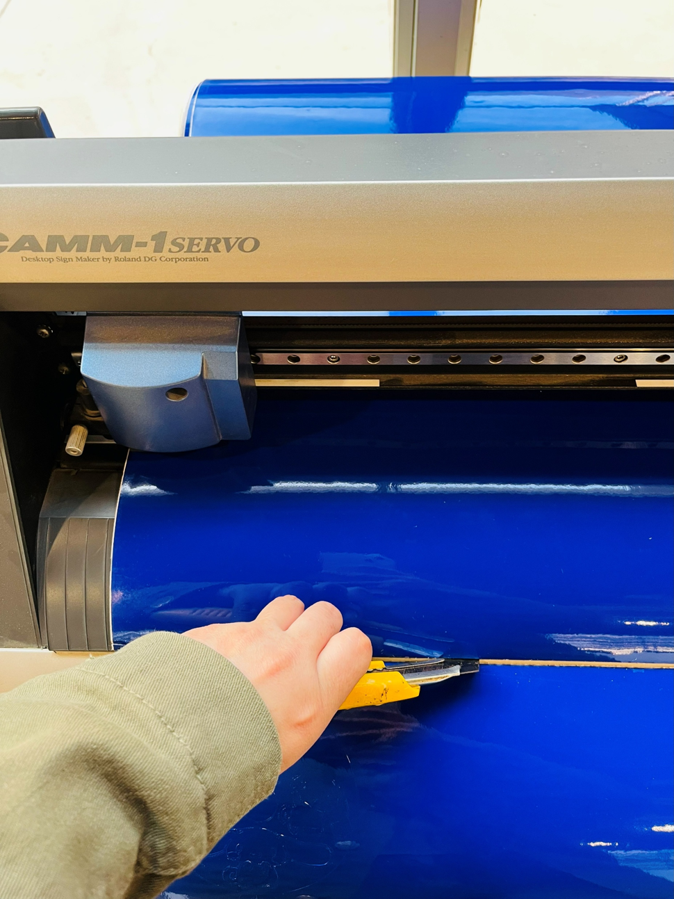
Removing the cut-out area
Applying the Vinyl Transfer
-
Once I had the piece of vinyl that was already cut, I placed a transfer sheet (also called transfer sticker) on top of it. This layer helps lift the entire design from the vinyl backing and makes it easier to position it on the desired surface.
- Here are the examples:
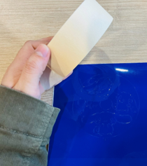
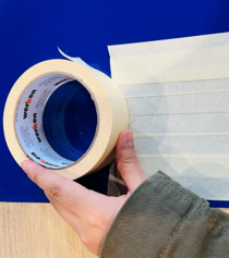
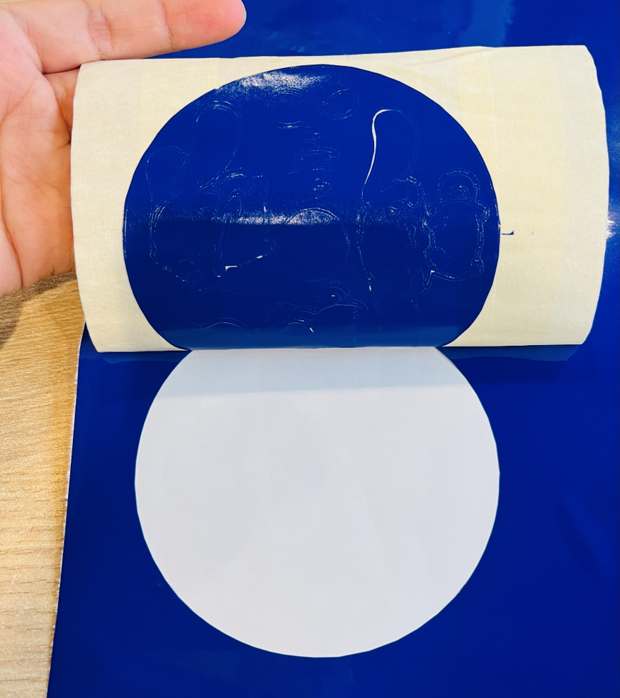
Process of applying the transfer paper -
After applying the transfer sheet, I carefully placed the vinyl onto the glass surface, pressing it firmly to make sure it adhered well. Then, I started removing the areas that would be sandblasted, leaving only the parts covered with vinyl to protect them during the process.
- Here are the examples:
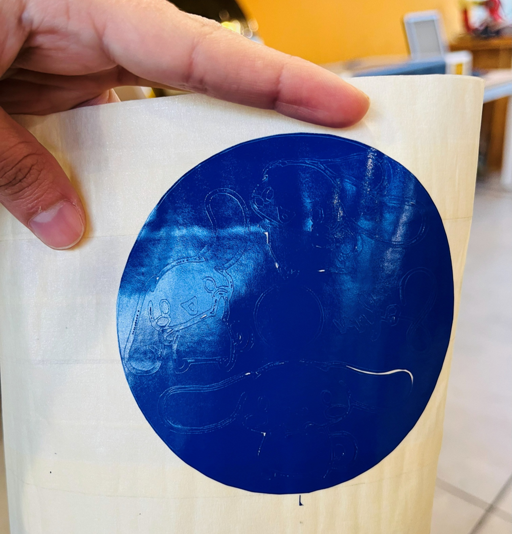

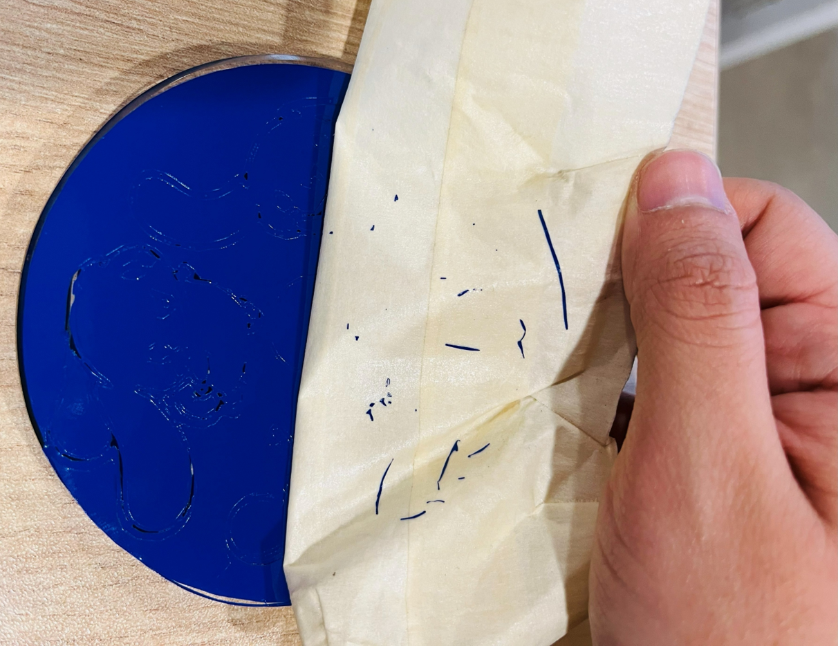
Process of removing the transfer paper- If the design is intended to be used only as a sticker and not for sandblasting, the same transfer process applies — you can place it on any smooth surface and simply remove the vinyl parts you don't need. For this step, I used a pair of tweezers to help peel off the small pieces of vinyl. It took a bit more time because of the complexity of the design, but the result came out just as planned. Here is the result:
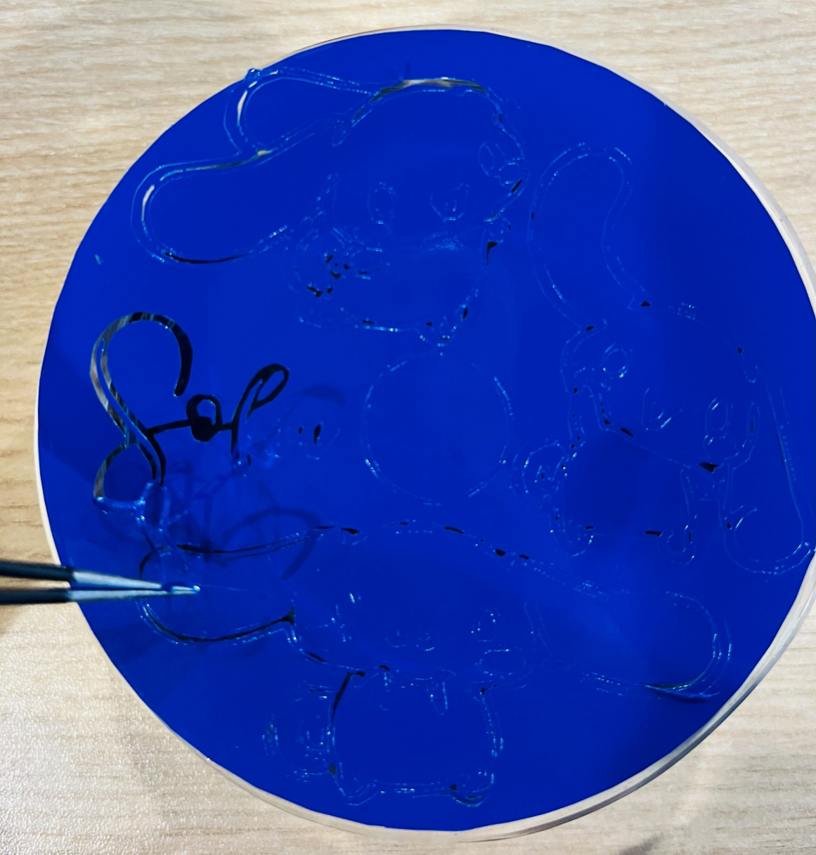
Removing the parts that will be sandblasted
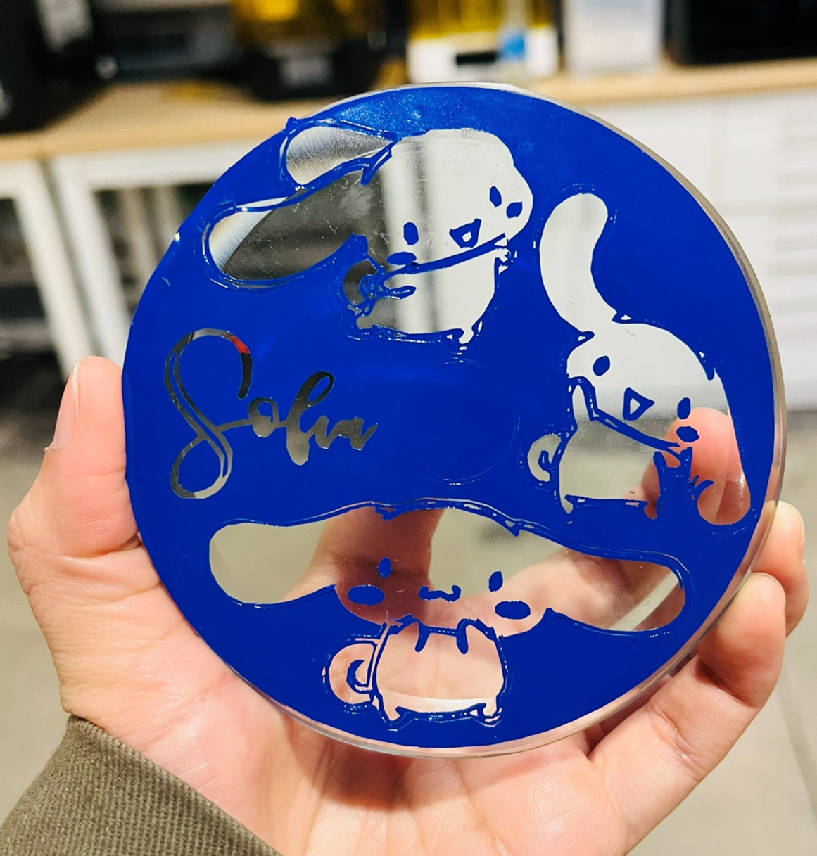
Vinyl mask ready for sandblasting
Sandblasting Process
This part was one of the most exciting steps! I worked on it together with Jorge, my local instructor, who helped me connect and operate the machine. The air pressure is quite strong, and the cabinet is a bit high for me, so teamwork definitely helped. 😄
Before starting, we made sure to connect everything carefully because the machines use different voltages, which means a transformer is needed. Once everything was ready and we had our safety equipment on, we used the sandblasting gun — a handheld tool that blows fine sand at high pressure to engrave the exposed areas of the glass.
As we moved the gun slowly and evenly across the surface, the design began to appear.
Using the sandblasting gun to engrave the glass surface
Once the sandblasting was finished, we put everything back in its place and turned off the machines. It was time to clean the exposed surface and remove the remaining vinyl sticker. After wiping away the dust and checking the engraved areas, the design was finally complete — and this was the result.
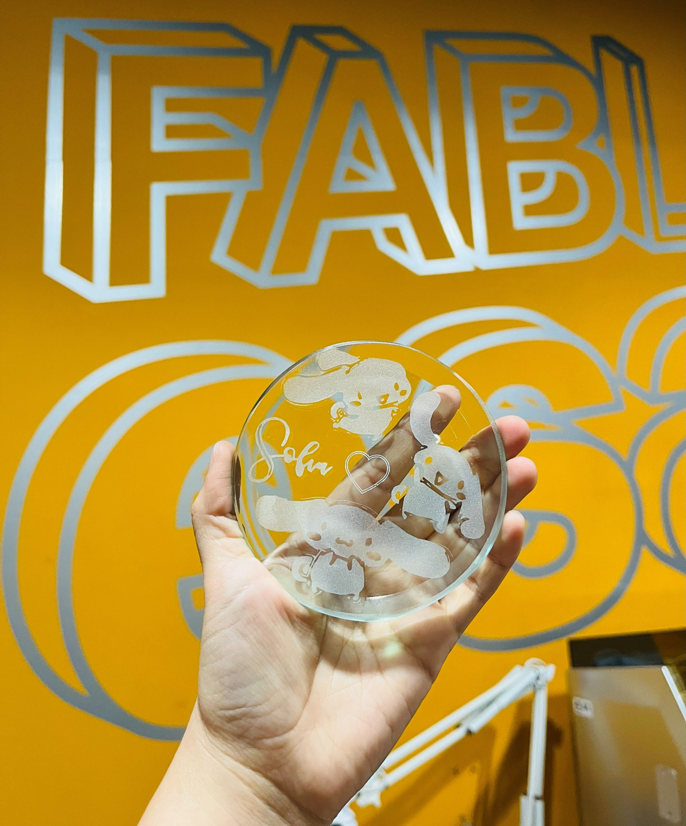
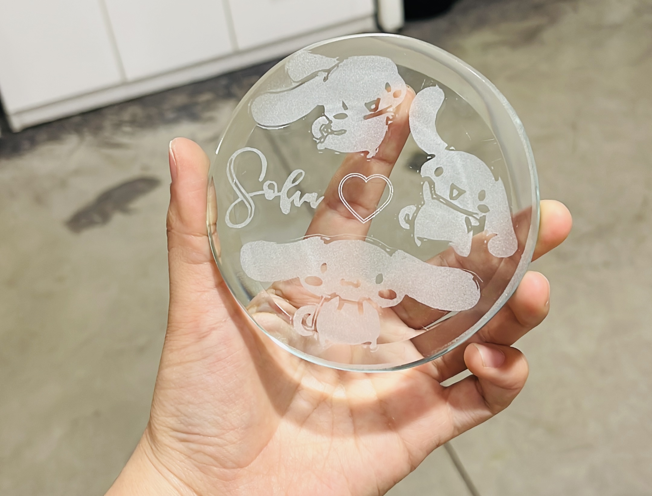
Final result: personalized Cinnamoroll glass coaster
Final Thought
As part of the 2025 cycle, I focused on the vinyl cutter, learning the complete workflow from design to cutting and application. In 2026, I expanded on this week's content by exploring the laser cutter, focusing on the design of parametric parts and their fabrication using the laser cutting process.