
W12 | Mechanical Design, Machine Design
XY (almost) Z Plotter
📹 Video:
📝 Poster:
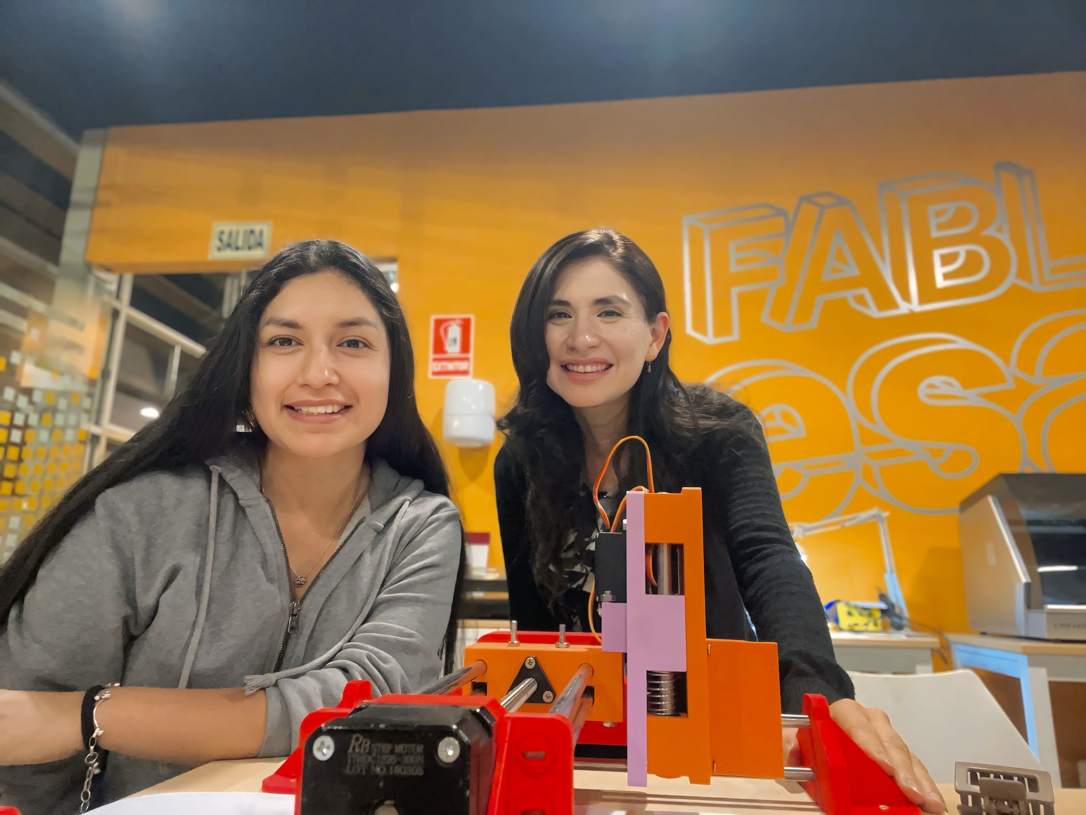
Individual Contribution
My individual contribution was the mechanical design of the machine. Using existing plotters as a general reference, I designed all of the custom parts from scratch to match the materials and components available to us, including the rails, stepper motors, and the Z-axis servo mechanism. The goal was to develop a structure that would integrate these specific components while ensuring proper alignment and functionality.
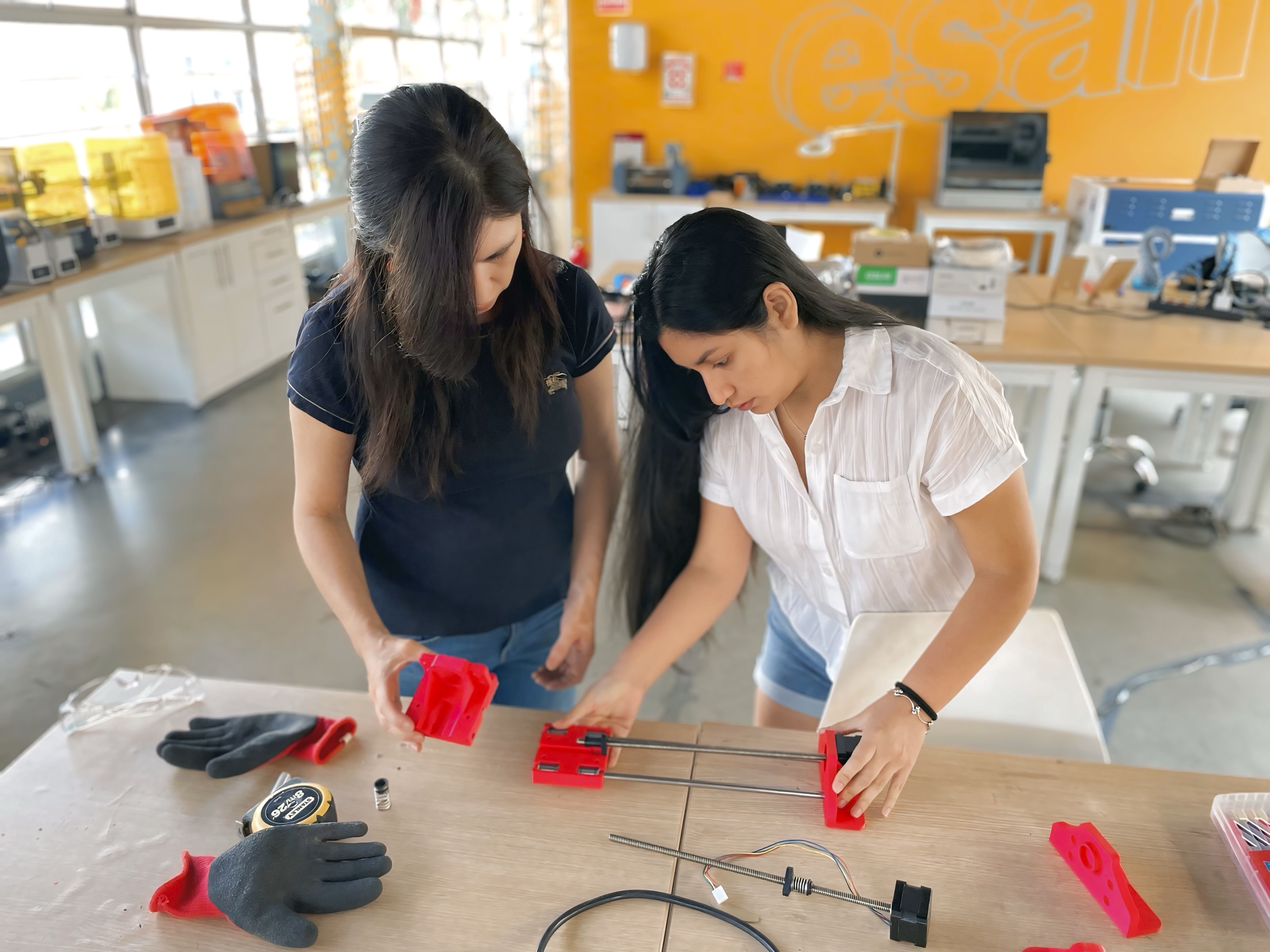
Once the design was completed, I moved on to fabrication and assembly. This involved 3D printing the custom components, preparing the CNC-milled base, and assembling the mechanical system. Special attention was given to the alignment of the rods and bearings to ensure smooth and reliable motion.
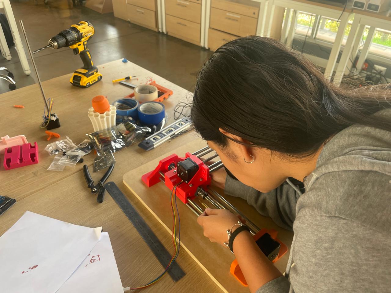
After the machine was assembled, I focused on the software configuration. Since no datasheets were available for the stepper motors, standard step/mm values could not be used. I therefore configured GRBL manually, calculating the required steps per revolution based on the leadscrew system and validating the results through iterative testing and adjustment until the machine achieved accurate and repeatable movement. 😊
What Machine to Choose? 🤔
This week's challenge was a big one — our group assignment asked us to go full maker mode and:
- Design a machine that includes mechanism + actuation + automation + application.
- Build the mechanical parts and operate it manually.
- Document the group project and our individual contributions.
Basically: build a real machine from scratch, make it move, make it smart, and explain everything. No pressure, right? 😅. So, when we got the assignment, we were like: "Cool! Let's build a machine!"… and then reality hit:
In the end, we decided to build a basic XY plotter. Why? Because it's an awesome way to understand how two-axis systems work, and it is an entry point into digital fabrication — combining mechanism, actuation, and automation in a way that's visual, hands-on, and super satisfying when it actually works. Plus, it's a solid foundation for more advanced machines in the future — like CNC routers, laser cutters, or even 3D printers.
We did a deep dive into other similar projects for inspiration, and got inspired by all the cool variations. We grabbed the best ideas, mixed them with our own, and little by little, our concept started to take shape.
Team Responsibilities
We both worked side by side throughout the project, from research and planning to building, testing, and documenting.
Jhasmin Ayala
I did the mechanical design of the machine. I modeled the structure and parts, making sure everything would fit and work together. I also participated in the fabrication, assembly, programming, documentation, and testing.
Marita Chang
Focused on assembly, electronics, programming, documentation, and testing. Even though this was her first time building a machine like this, she was super hands-on and did an amazing job figuring things out along the way.
We made a great team — figuring things out as we went, learning from our mistakes, and celebrating every tiny success. 💪 And even though our machine may not be perfect — it works, and we learned a lot along the way. There were falls, stumbles, moments of "why is the stepper motor doing that?!", but we pushed through and made it happen.
Is it perfect? Nope. Is it functional? Yes! Did we learn a lot? Absolutely. 🚀
Design 3D
We originally planned to build a basic XY plotter, but then we found a video of a machine that could switch between colors while drawing — and we were instantly hooked. To do that, we needed to add a Z-axis, which would control the up and down movement of the pen (or marker). Our simple plotter turned into a much more ambitious (and slightly more chaotic) project.
Before starting the design, we had to consider all the technical components that would define the machine's structure. Since we were working with stepper motors for the X and Y axes, a servo motor for the Z-axis, and an extra servo to grab and release the marker, the design had to fit around those parts. We also used an Arduino Uno with a CNC shield, and our software would run on GRBL. With all that in mind, the goal was to create a design that brought these elements together smoothly — and actually worked in real life.
We used Fusion 360 to design the whole machine. To keep everything accurate, we imported models of the stepper motors from McMaster-Carr, and added STEP files for the servos. That helped us design the custom parts around real dimensions.
Assembling the machine virtually allowed us to catch issues early and make quick adjustments. After many tweaks, we had a solid design ready for fabrication!
Fabrication
For the fabrication process, we used two main digital manufacturing technologies:
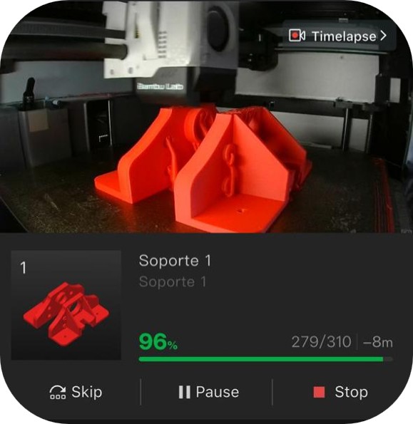
3D Printing
We printed a total of 12 custom parts for the plotter, including supports, mounts, and the pen mechanism. Each piece was designed to fit precisely with the components we selected.
CNC Milling
We used the CNC to cut a solid MDF base, which serves as the platform where the entire plotter is mounted. This gave us a strong and stable foundation to work on.
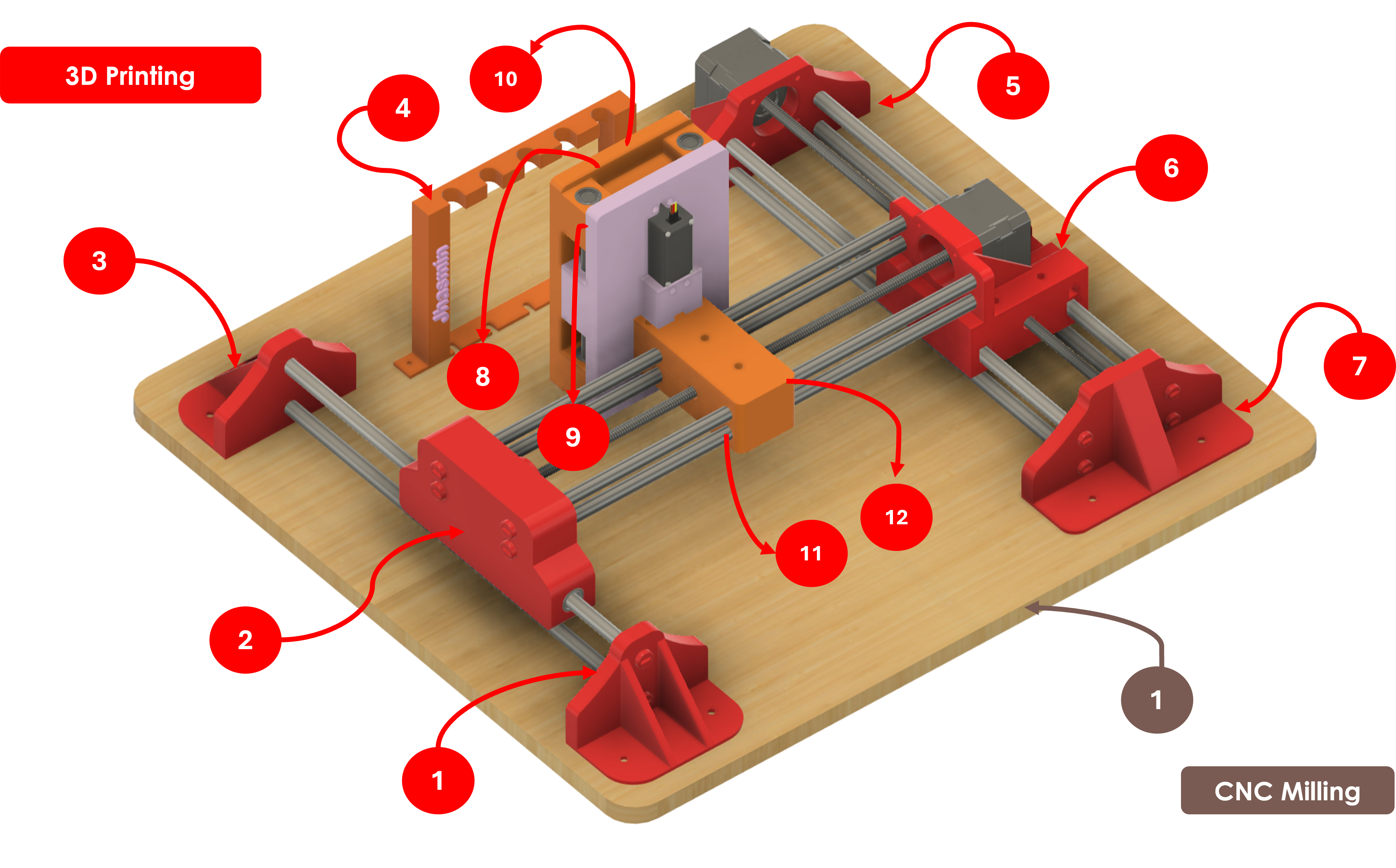
3D printed parts and CNC milled base used in the plotter
Assembling
Before putting anything together, we made sure we had all the components ready to go. That included:
- The 12 3D printed parts and the CNC milled base.
- All mechanical components like bearings, metal rods, screws, and nuts.
- The electronic parts, including stepper motors, servo motors, the Arduino, and the CNC shield.
All the components we used are detailed in the following table:
| Item | Qty | Use |
|---|---|---|
| Linear bearings | 8 | Facilitate the movement of the component with the pen on the Y-axis |
| Circular bearings | 4 | Fix the steel rods to the 3D printed bases |
| Steel rods 8 mm (31.5 cm) | 8 | Provide stability to the base of the structure |
| Rods 8 mm (14.2 cm) | 2 | Used to place springs and assemble the part that supports and moves the pen |
| Arduino Uno | 1 | Microcontroller that connects the program with motors and servos |
| DC motor shield | 1 | Regulates motor functionality |
| Servomotors | 1 | Controls movement on the Z-axis |
| Nema17 linear screw stepper motors | 3 | Controls movement on the X and Y axes |
| MDF cut (50x45 cm) | 1 | Base that supports the structure |
| Wires | — | Connect motors, power supply, and Arduino |
| Screws and nuts | — | Fix the parts of the machine |
| 12V Power supply | 1 | Provides power to the machine |
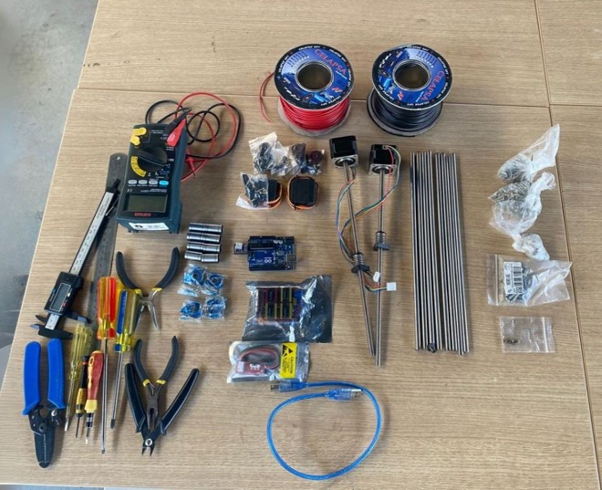
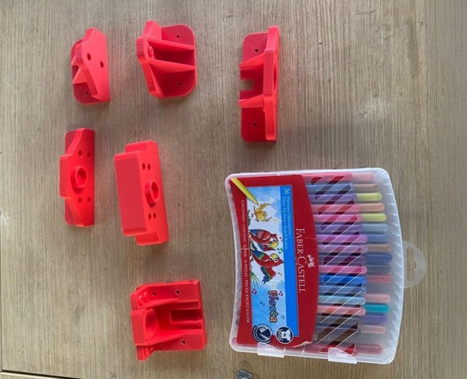
Components (mechanical, electronic, and some 3D printed parts)
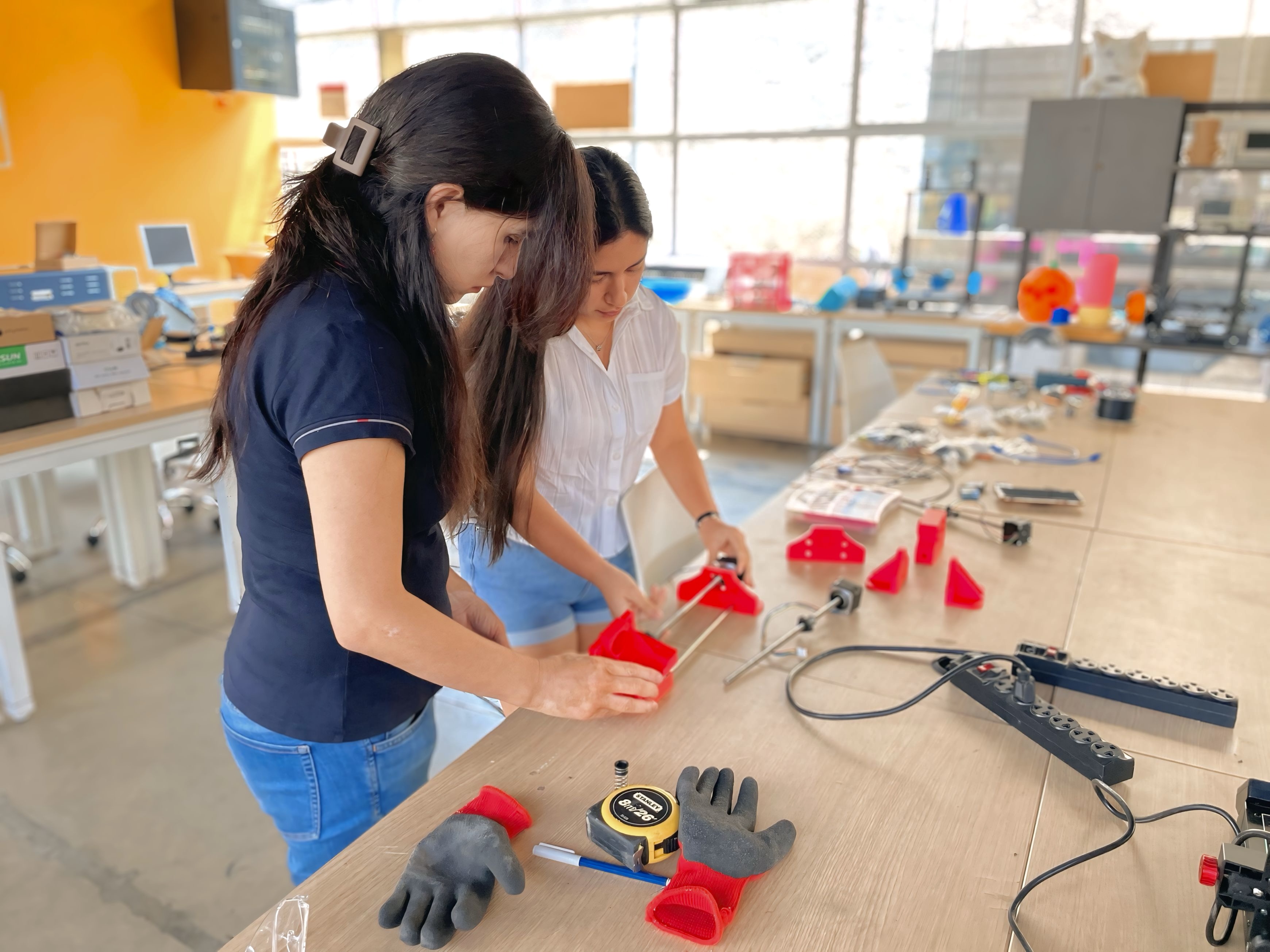
It's finally time to put everything together! During the assembly process, there were a few crucial things to keep in mind:
- Alignment is Key: The rods, bearings, and 3D printed components needed to be perfectly aligned to ensure smooth operation when the motors started moving.
- Secure Everything: All parts had to be tightly fastened with screws and nuts — no loose or wobbly components allowed!
- Stability: The entire structure had to be securely attached to the CNC-milled base to ensure maximum stability.
Programming and Software
To bring our XY (almost) Z plotter to life and turn it into a real CNC machine, we needed two key things:
- Firmware installed on the Arduino to control the machine's motion.
- Control software to send G-code instructions and manage the plotting process.
For the firmware, we used GRBL — an open-source firmware that runs on Arduino and interprets G-code to control stepper motors with high precision.
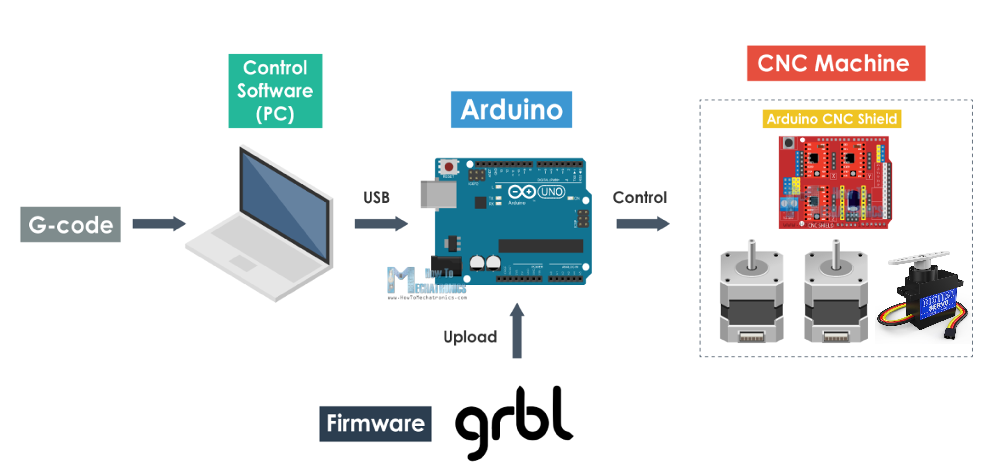
For the control software, we used GRBLPlotter — specifically the servo version, since our design includes two servo motors. One servo is used to lift and lower the pen, effectively enabling movement along the Z-axis, while the second servo allows the plotter to grab and release the pen.
This setup is slightly different from the example we were following, which originally used a DC motor for the Z-axis. We decided to modify it by using a servo motor instead, giving us more precise and simpler control for the pen's vertical movement.
With everything connected and configured, GRBLPlotter allows us to send G-code to the Arduino, which in turn tells the stepper motors and servos exactly how to move — turning code into motion.
Control Software & GRBL Parameters
For controlling our plotter, we used GRBL-Plotter, an open-source software specifically designed for plotters. It includes a built-in graphics converter that allows us to generate G-code from images or vector graphics, making it easier to send drawing instructions to our machine.
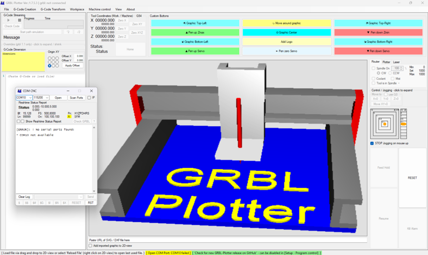
Once the software was set up, the first critical step was to configure the GRBL parameters, especially the travel resolution (steps/mm). This value defines how many steps the stepper motor needs to take to move 1 mm and depends on factors such as the motor type, step resolution, and motion transmission system.
Challenges & Solutions
Throughout the project, we ran into challenges on two fronts — software configuration and mechanical design. Here's how we tackled each one.
Software
1. Limited documentation and tutorials
Problem
The GRBL-Plotter version we used didn't have many reference videos or guides, making it hard to understand its full functionality.
How we solved it
We relied on testing and exploration, figuring out the software's behavior through trial and error until we understood how it worked.
2. Z-axis configuration issues
Problem
The original example used a stepper motor for the Z-axis, but we replaced it with two servo motors. The G-code commands had to be manually adapted, which wasn't straightforward.
How we solved it
We manually adapted the G-code commands and confirmed the servo moved as intended, even though full integration with the controller interface remained a challenge.
Mechanical
3. Custom mechanical setup
Problem
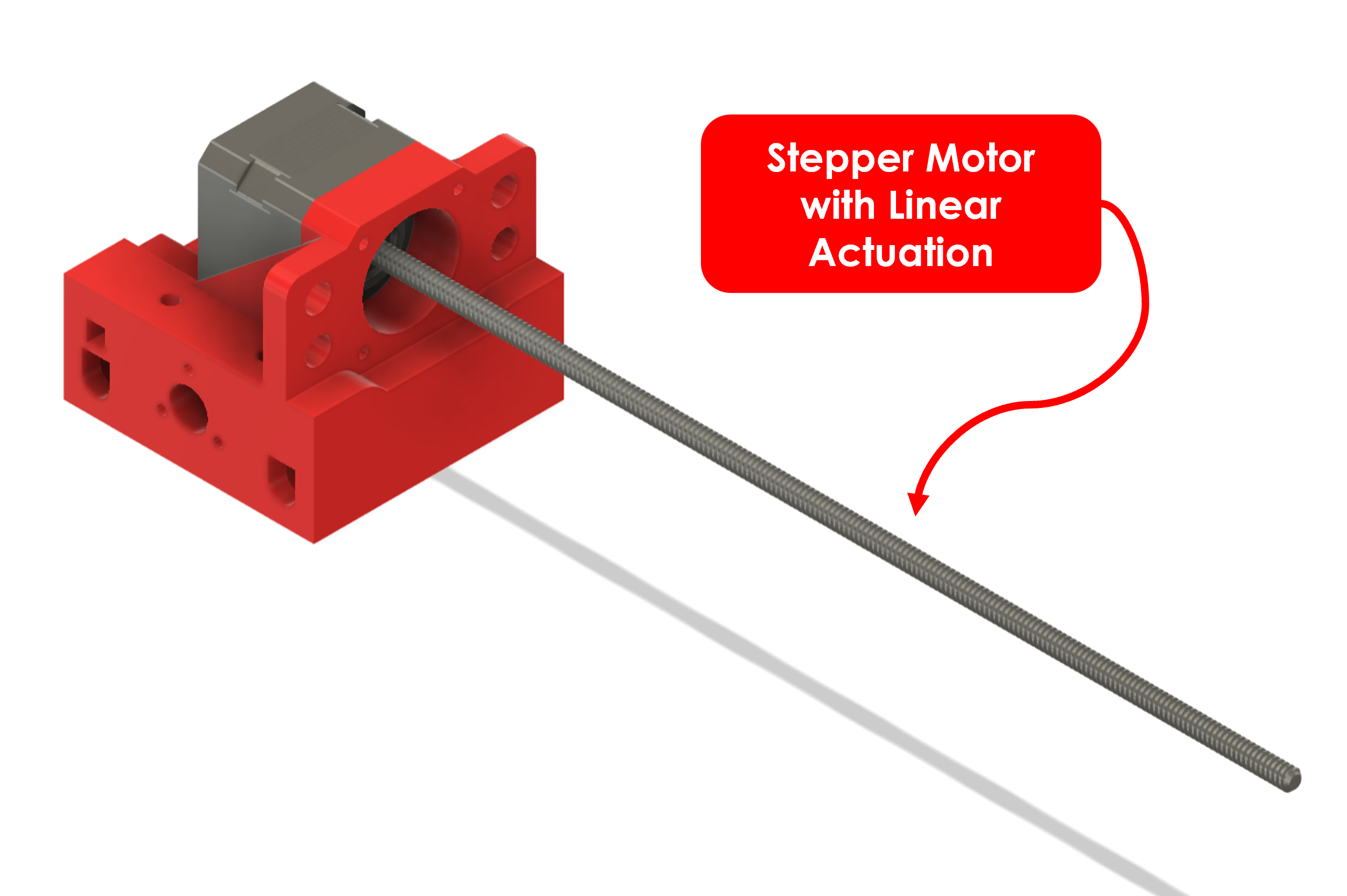
Our setup used threaded rods (leadscrews) instead of rails, so we couldn't use the standard step/mm values. We also had no datasheets for our stepper motors.
How we solved it
We determined the movement per revolution manually through trial and error until we found the correct steps/mm values for the X and Y axes.
4. Color change feature
Problem
We couldn't fully integrate the Z-axis with the controller software to perform coordinated Z-axis operations during plotting, even though GRBL-Plotter technically supports this feature.
How we solved it
We confirmed that the servo responded correctly in isolation, but couldn't configure it within the controller's interface. This remains a pending improvement for the next version of the machine.
Possible Improvements
Future improvements we have in mind:
- Fully integrate the Z-axis with the controller software to enable automatic pen color changes during plotting.
- Replace the threaded rods with linear rails for smoother and more precise movement.
- Obtain proper stepper motor datasheets to calibrate step/mm values more accurately.
- Improve the pen grabbing mechanism to make color changes faster and more reliable.
Final Thought
As part of the 2026 cycle, I revisited the group project developed during the 2025 cycle. This included adding files that had not been uploaded previously, completing missing sections of the documentation, and updating the project record to better reflect the work that was carried out. In doing so, I also had the opportunity to reflect on and document my individual contribution to the project. Revisiting the development process helped me remember the decisions, challenges, and tasks I was responsible.