This week we're learning about different Inputs, measuring their values with our board, and making some noise.
Requirements
- Probe an input device(s)'s analog levels and digital signals
- Document your work to the group work page and reflect on your individual page what you learned
Group Assignment
Individual Assignment
- Measure something: add a sensor to a microcontroller board that you have designed and read it.
Softwares 💻
- KiCAD
- MODS
- GIMP
- Arduino IDE
Group Assignment
In the group assignment we read the values of both soil sensor and microphone sesnor plus potentiometer. I'll document the soil sensor and microphone sensor.
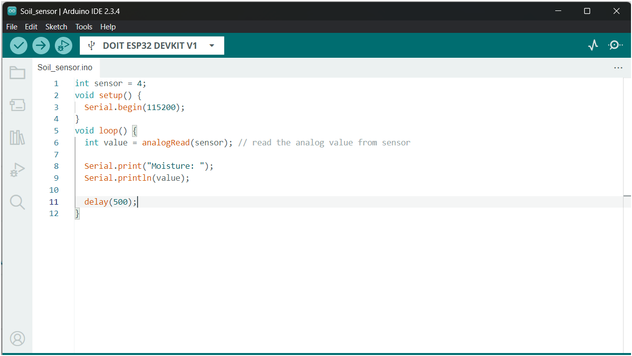
Measuring Analog Signal
First me an Doaa took thesoil sensor and started and use a simple code to display the reading of the sensor on the serial plotter and watched the fluctuations. We could see the transition from ~+1000 to ~800 once she put it in the water but we saw the noise as well.
This is logical since the probe is an exposed conductor that acts like a potentiometer its resistance vary inversely with the moisture. When Doaa put it in the water, its conductivity got higher, therefore the resistance was lowered. The sensor produces an output voltage based on the resistance
Measuring Digital Signal
The Microphones are devices that convert the sound energy into electrical energy. Their sensors help an electronic product capture sound waves. The type we use is an Electret microphone (ECM). They use electrostatic and magnetic properties to function with an electret diaphragm that acts as a single capacitor plate. Once a signal is captured due to variation in capacitance, it's amplified.
We measured the signal raw at first and THE NOISE was Maddening, so Saeed introduced us to the art of calibrating our sensors with coding. We tuned the readings until it showed only the signal.
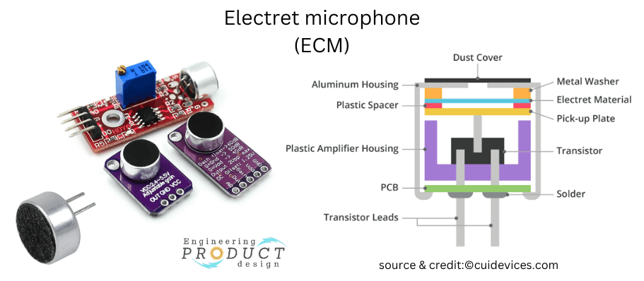
Credits: Engineering Product Design
Reading on the plotter
Individual Assignment
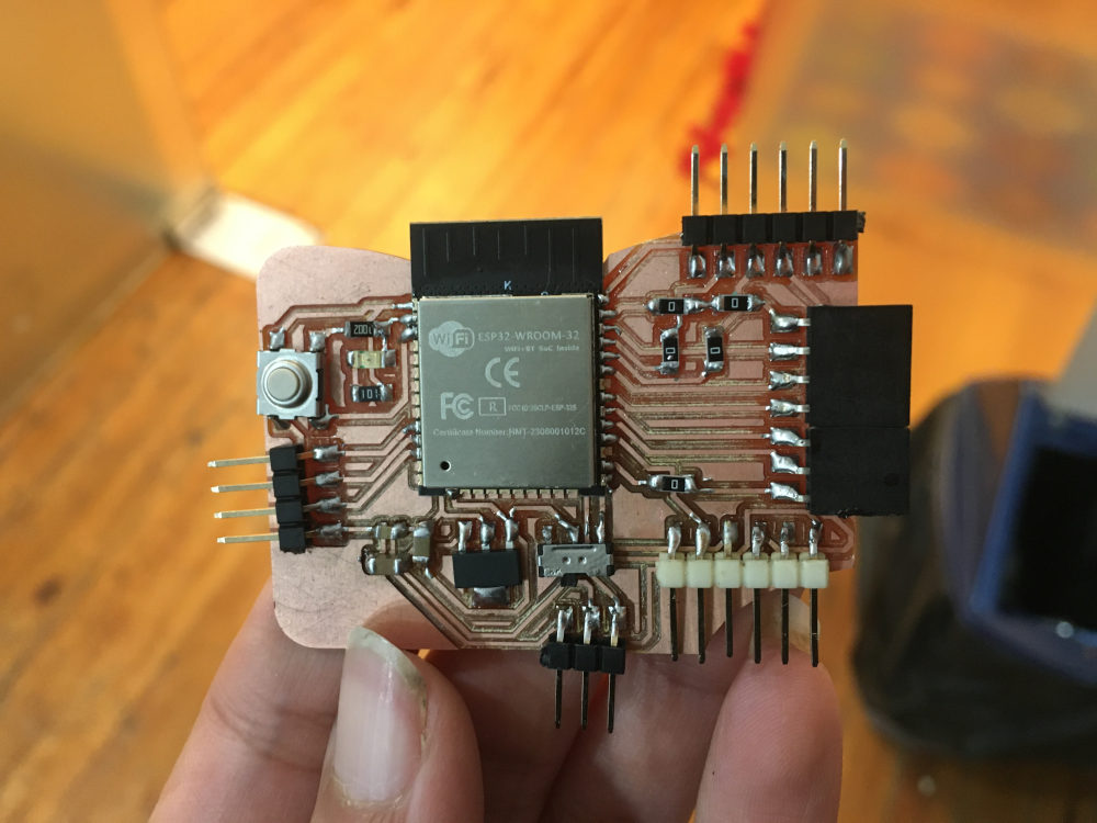
I wanted to measure analog components this week but I found my board I designed in pervious week was not suffiect. I made a new one using the same compoenets but adding more pinheaders for I2C, analog, FTDI, SPI, and power.
Components PCB
My components are listed in week 6's page . I added more Zero ohm resistors that can act as bridges. And lots of pinheaders for power, FTDI, Analog GPIOs and Pinsockets for I2C and SPI. Then I removed the input Button & Output LED.
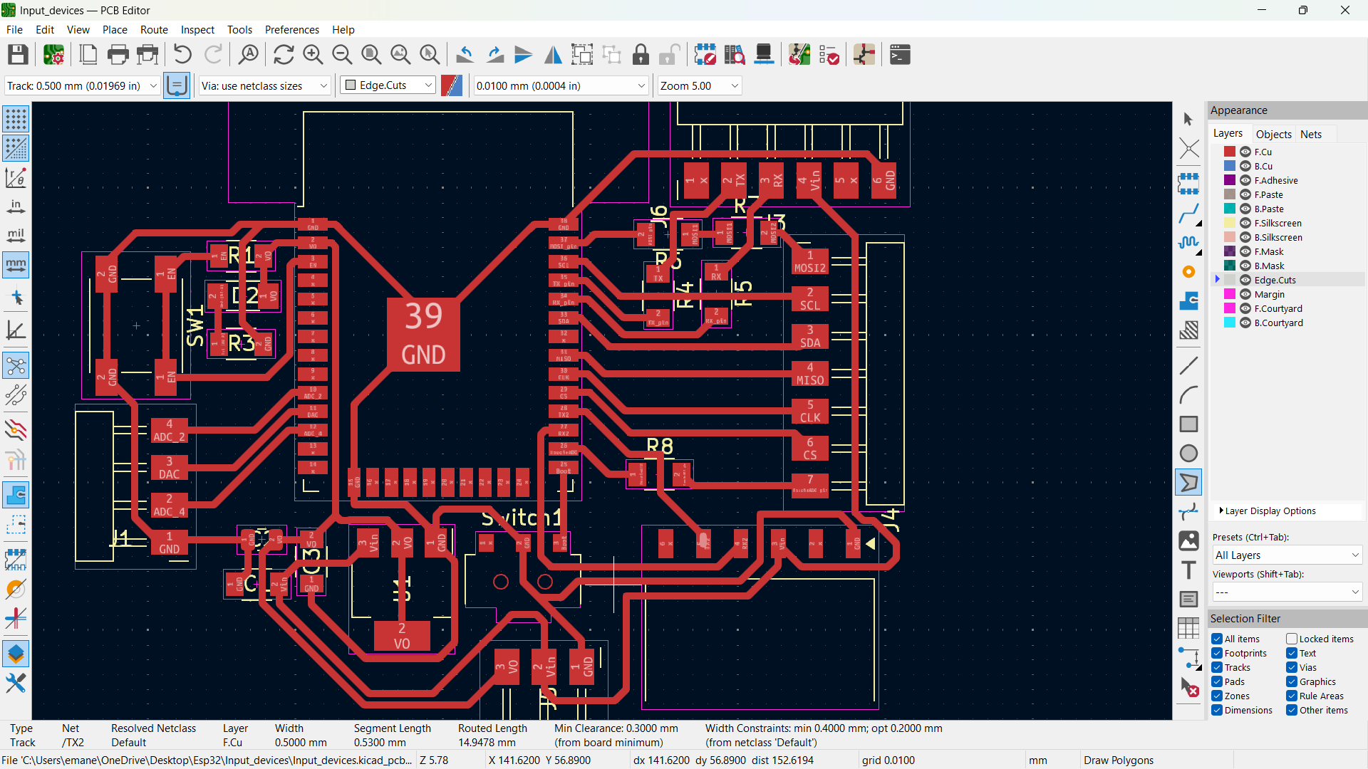
PCB Design in KiCad
I used the same design but modified some things.
Schematic & Layout
After I made the things a bit neater I added the 0 ohm resistors in put them is rectangle with the name "Bridges". I like to arrange by functionality in my schematics.
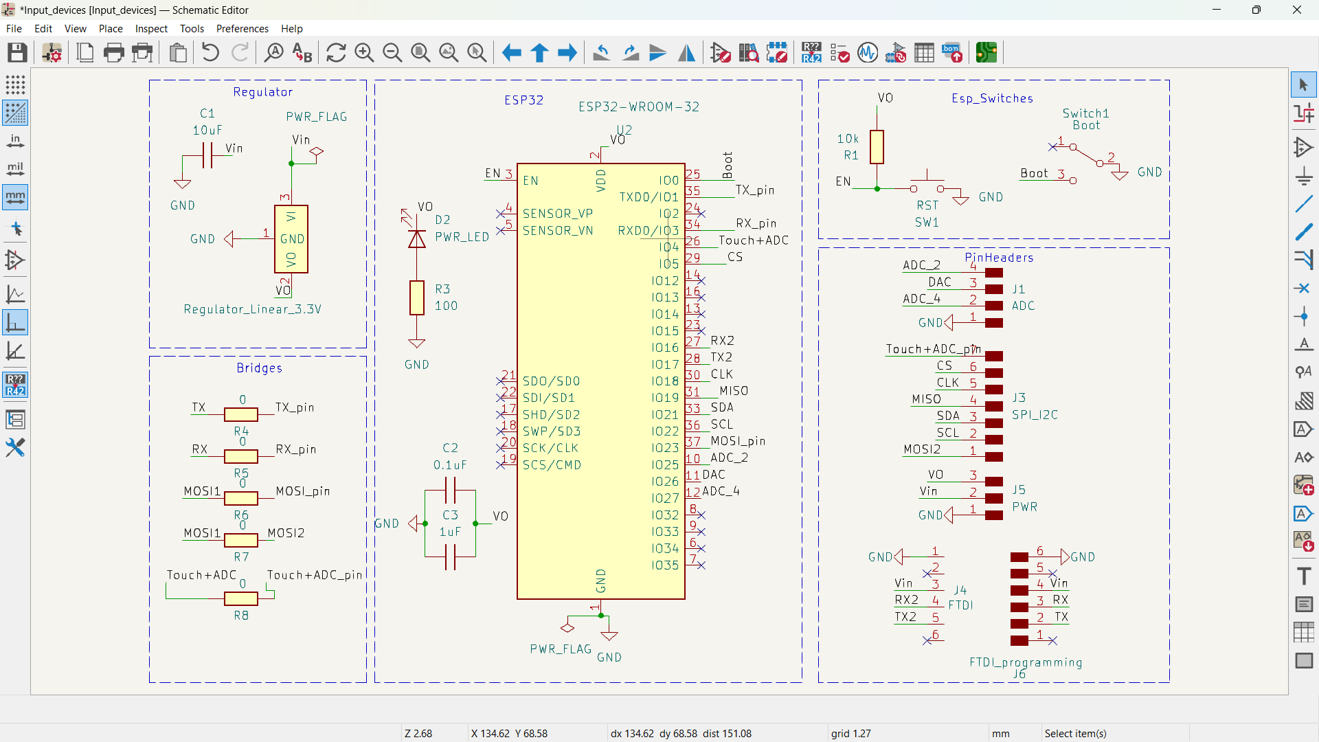
My schematic in KiCad
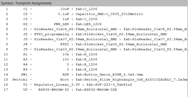
Footprint
Then I made the layout and added the traces.
My schematic in KiCad
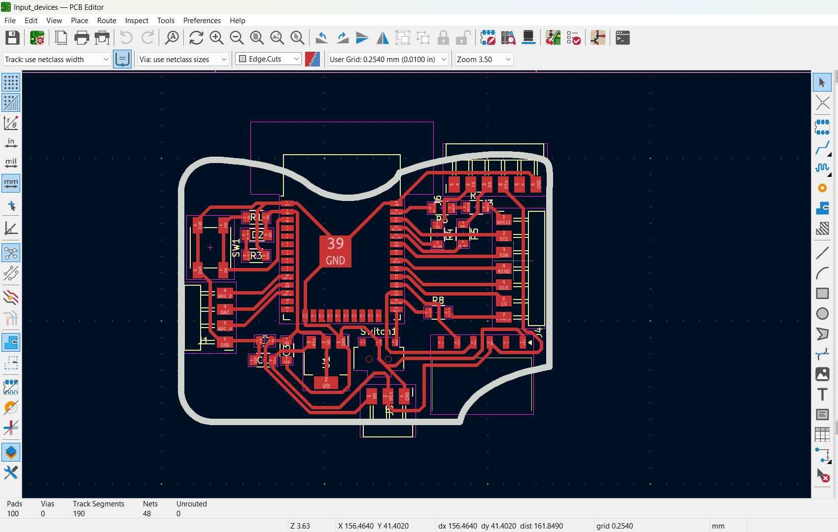
Footprint
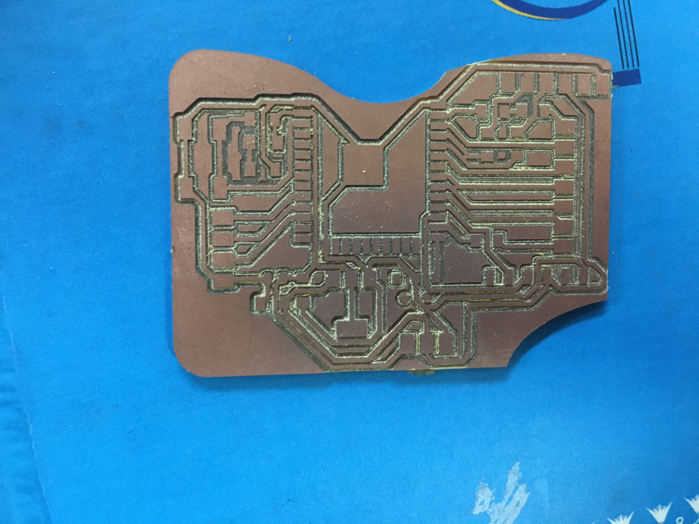
Fabrication
I used the same pcb process I made in my previous weeks. I used our china router cnc milling machine.
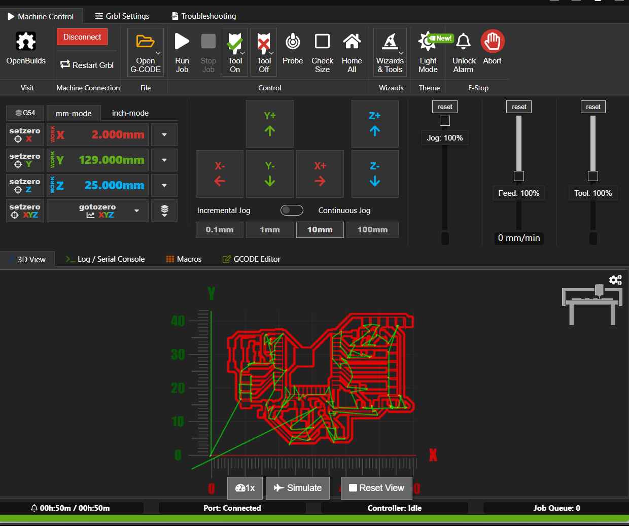

PCB in the making
Soldering
Measuring
I had my head set on trying joystick, capacitive touch and saeed offered me the radar sensor to try out.
Radar
This sensor is called RCWL-0516 and it can detect movement using the famous-if you're into astronomy you know it's famous normally referred to as redshift- "Dopler Effect". It's the change of frequency of a wave in relation to an observer who is moving. Since they depend on the frequency of the wave, they are not affected by the temperature of the object and they detect movement in 360º.
I used the board I made in week 6 for easier usage.
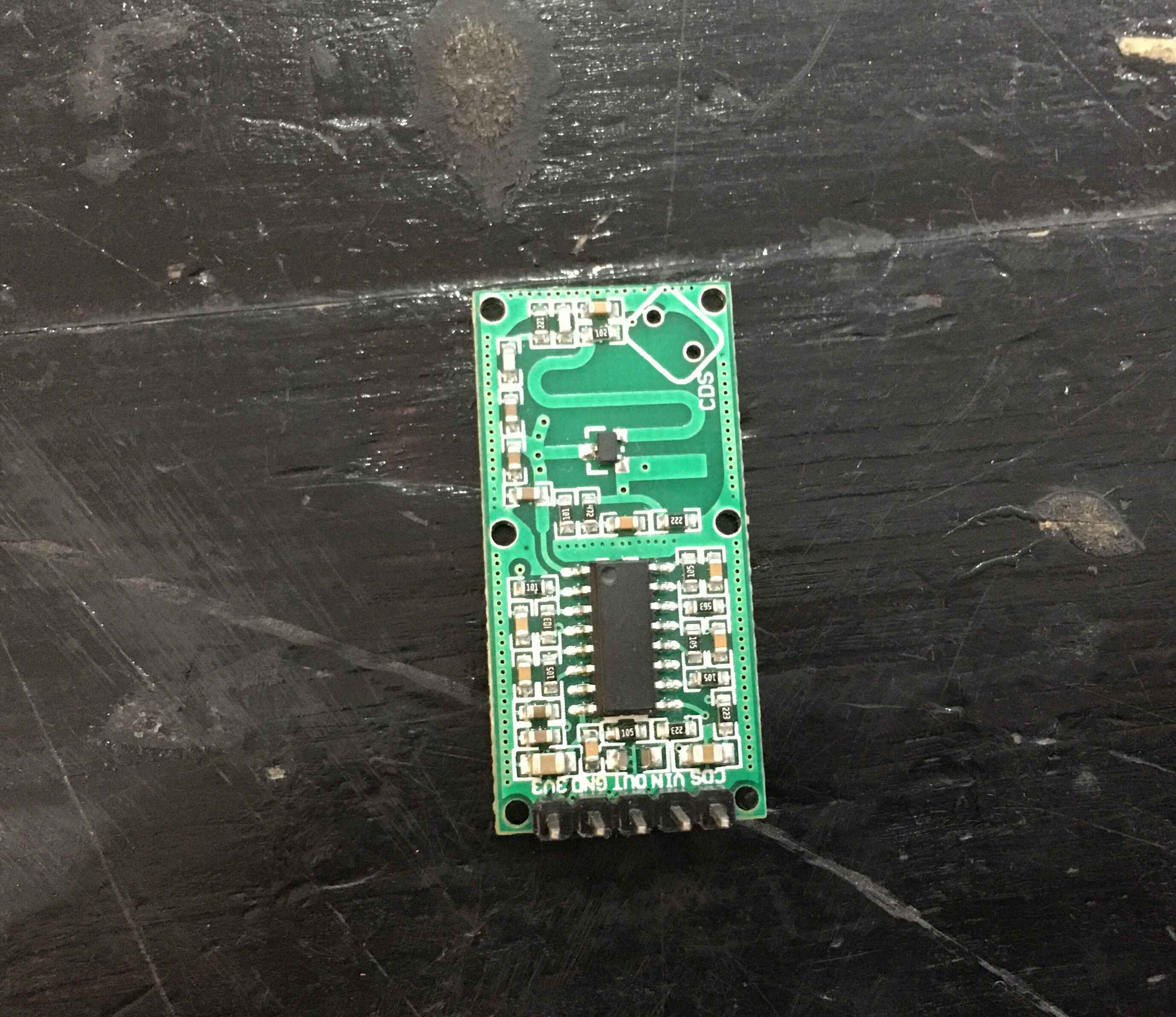
Radar Sensor
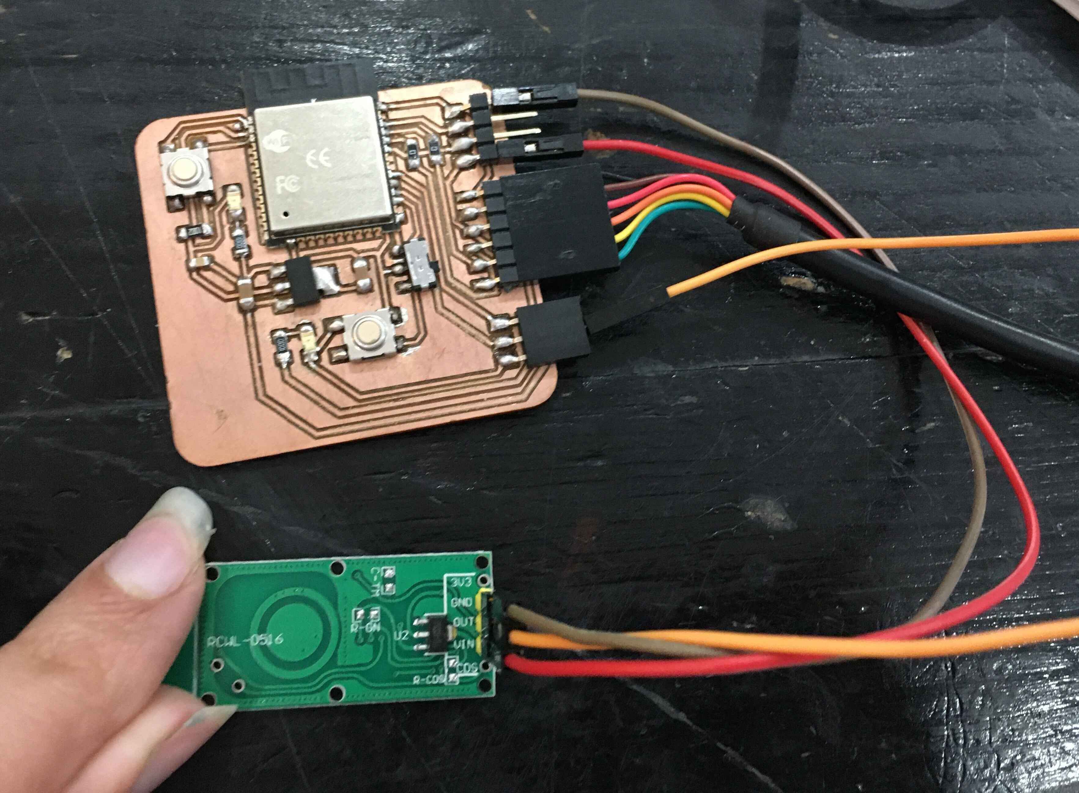
Wiring
At first, I used adrian's code to print the value the sensor reads it on the serial but the sensor was kind of buggy and the reading arrived delayed a bit. So I tried the technique Saeed honed in us: "FLAGING" -insert dramatic sound effects.
So I made reading one for the current and one for the previous reading and compared them in every condition. The delayed response was shorter.
The Code
int current_reading;
int past_reading;
const int RadarPin = 17;
void setup() {
Serial.begin(115200);      // initialize serial communications
   pinMode(RadarPin, INPUT);  //digital input pin
   }
 void loop() {
  current_reading = digitalRead(RadarPin);  // read the value from the sensor (0 or 1)
if (current_reading == 1 && past_reading == 0) {
past_reading = 1;
Serial.println("GOTCHA!");
}
if (current_reading == 0 && past_reading == 1) {
past_reading = 0;
Serial.println("WHERE ARE YOU?");
}
}
Joystick
The joystick is present in game controllers and can be used to move robot arms. This is a very useful guide to fully understand the joystick from one Minute Engineers. But briefly they're two potentiometers connected to the joystick through a mechanical system called a "gimbal mechanism".
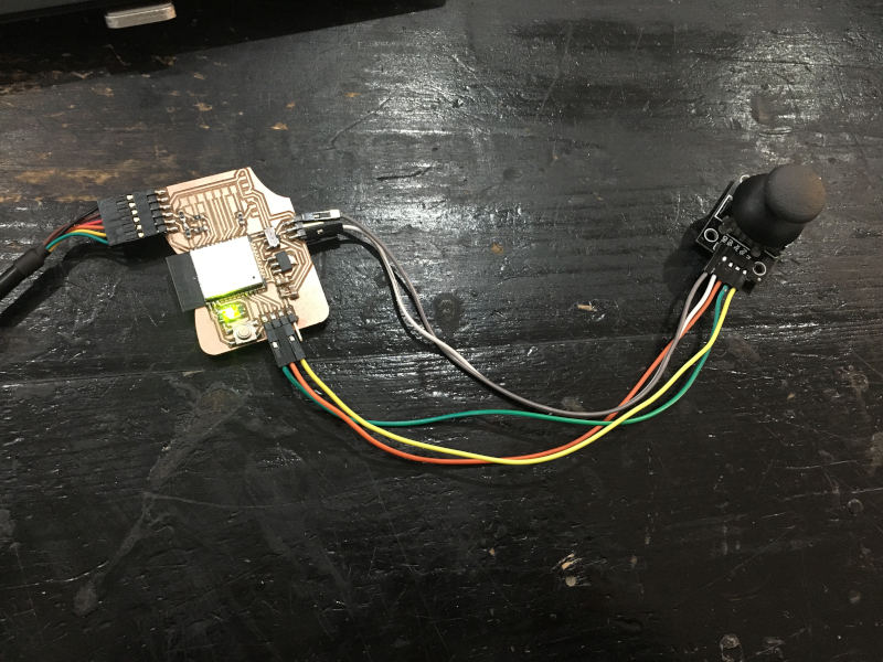
I used the code provided from ESPIO to print the values from the x and y movement on the serial.
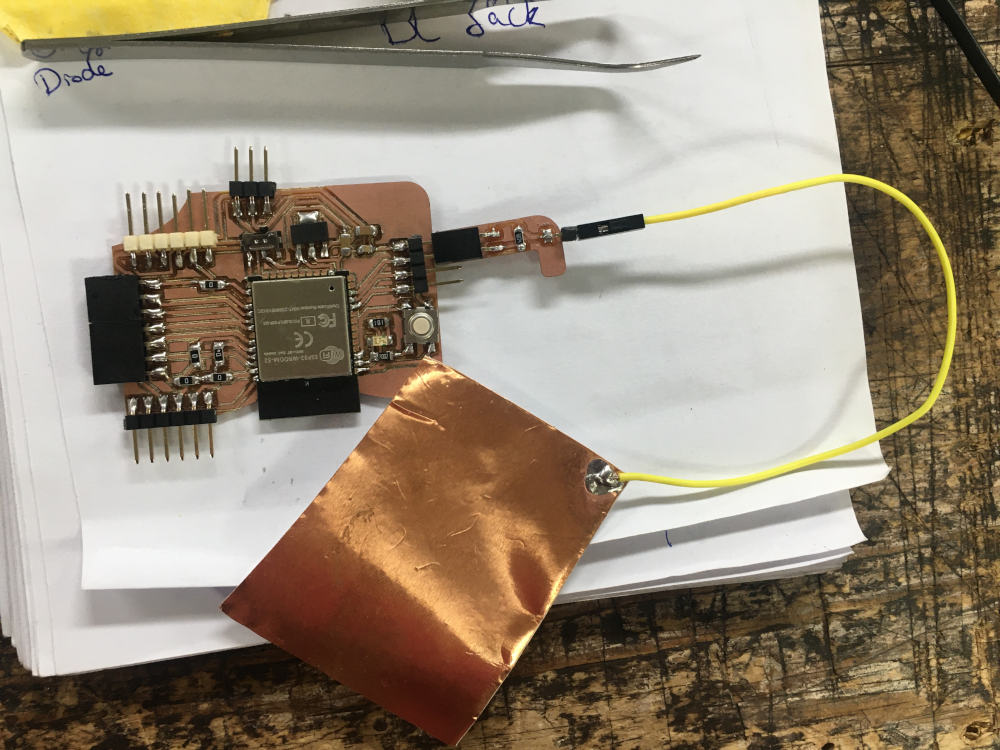
Capacitive Touch
When I heard about the concept of step response in the lecture I was interested to check it out.I was more interested to try out to make it an accelometer as robin hart did but I ended up making an capacitive touch instead since it was easy to follow and grasp. Briefly the The Capacitive Touch is a sensor that is made with one sheets of copper. That can be used to detect the touch by sensing the change in voltage as the plate charges up. The closer the grounded object is to the plate, the larger the capacitance, and the longer it takes to charge.
I designed a small pcb with one 1 Millino Ohm resistor.
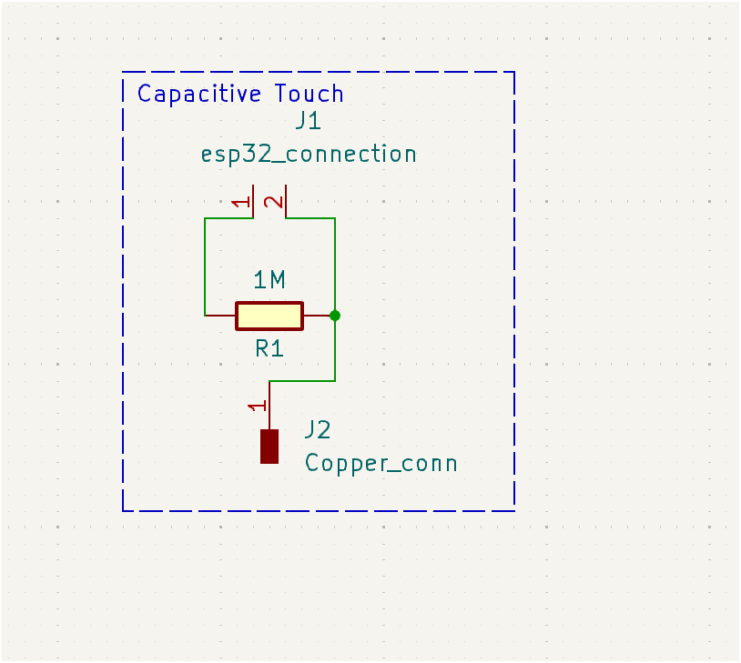
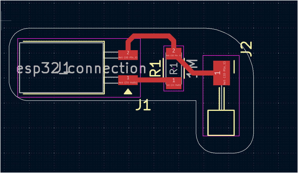
Capacitive Touch PCB in KiCad
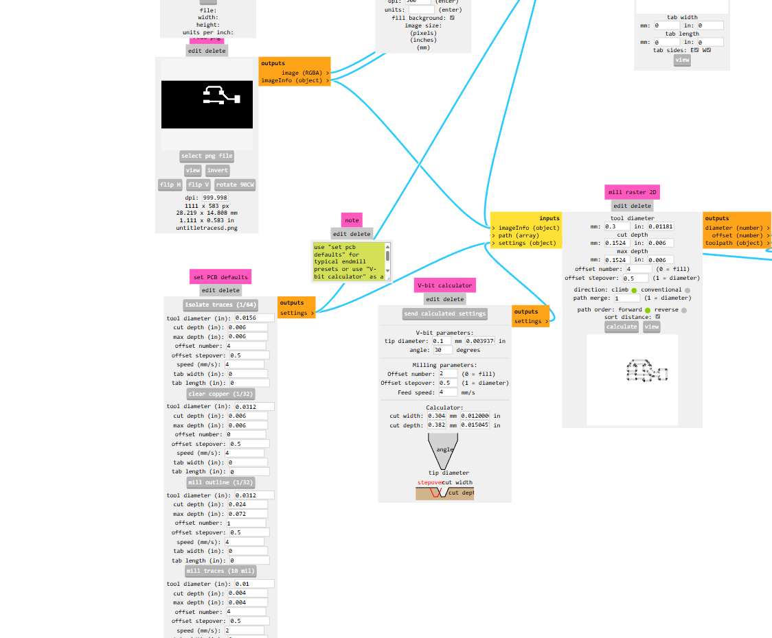
I went through the same process I mentioned in week 6 on pcb fabrication.
Wiring
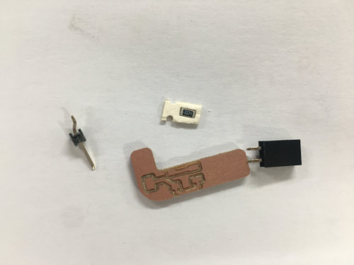
PCB components
Wiring
Luckily I read Tarek's documentation and saw he installed this library I had no diffucilty in making it work after istaalling the library.
The Code
   #include FastCapacitiveSensor.h>
    #define send 27
    #define receive 26
   FastCapacitiveSensor sensor;

  void setup() {
    pinMode(send, OUTPUT);
   pinMode(receive, INPUT);
  Serial.begin(115200);
  sensor.begin(send, receive, 1.85, 500, 500, 0.3);
    }
   void loop() {
    if (sensor.touch()>100){
   Serial.println("Touched");}
    }