This week we're learning about Communication, Networking, how to control components, and send messages.
Requirements
- Send a message between two projects
- Document your work to the group work page and reflect on your individual page what you learned
Group Assignment
Individual Assignment
- design, build and connect wired or wireless node(s) with network or bus addresses and a local input and/or output devices
Softwares 💻
- Arduino IDE
Group Assignment
In this group assignment I tried wired communication between my board and an Arduino.
We started with explaining what are communication protocols and focused especially on the wired ones.I found this article that explains the difference between UART, SPI, and I2C. I also found this lecture note that has multiple resources to read for each protocol.
We focused on making a wired connection between two projects for my case:my Esp32 board I made in PCB Production week and an Arduino. Briefly the UART protocol It's a hardware integrated in Microcontollers that communicates via the serial port. It is capable of full duplex communication meaning it can both send and receive signals simultaneously. It uses the RX and TX pins or configure other pins to be RX & TX using the softwareSerial Library.
I wanted something simple to test this, so I made a button connected on the Arduino control the led on my Esp32 board I made in PCB Production week here. And a button is connected to the ESP32 board will control a Arduino buildt-in LED
.jpg)
The wiring and schematic of the group assignment
Slave Code
  #include SoftwareSerial.h>
  int Arduinobutton = 8;
  const byte rxPin = 2;
  const byte txPin = 3;
  SoftwareSerial mySerial(rxPin, txPin);
  void setup() {
  Serial.begin(115200);
  mySerial.begin(115200);
  pinMode(LED, OUTPUT);
  pinMode(Arduinobutton, INPUT_PULLUP);
  }
  void loop() {
  if (mySerial.available() > 0) {
  char number = mySerial.read;

  if (number == '0') {
  digitalWrite(LED_BUILTIN, HIGH);
  }
  else if (number == '1') {
  digitalWrite(LED_BUILTIN, LOW);
  }
  }
  if (digitalRead(Arduinobutton) == HIGH) {
  mySerial.print('4');
  Serial.println('4');

  } else {
  mySerial.print('2');
  Serial.println('2');
  }
  }
First we call upon all the libraries we'll need
#include SoftwareSerial.h>
Then we initialize the Serial. We define the RX and TX pins and Arduino Button which will control the
Led
on my ESP board.
    int Arduinobutton = 8;
    const byte rxPin = 2;
    const byte txPin = 3;
    SoftwareSerial mySerial(rxPin, txPin);
In the Void Setup We begin the hardware and software serial and assign their baud rate. We set the LED
pin
to output.
    void setup() {
    Serial.begin(115200);
    mySerial.begin(115200);
    pinMode(LED_BUILTIN, OUTPUT);
    pinMode(Arduinobutton, INPUT_PULLUP);

     }
In the loop we check if the software serial has any data available. If it does, we read the incoming
number hold in a character.
Then add an if condition based on the data incoming to set the LED on the arduino to light up or turn
off.
And add a new condition that sends number based on the button's state.
  void loop() {
    if (mySerial.available() > 0) {
      char number = mySerial.read;

      if (number == '0') {
       digitalWrite(LED_BUILTIN, HIGH);
        }
      else if (number == '1') {
        digitalWrite(LED_BUILTIN, LOW);
        }
      }
      if (digitalRead(Arduinobutton) == HIGH) {
       mySerial.print('4');
        Serial.println('4');

         } else {
        mySerial.print('2');
       Serial.println('2');
        }
     }
Master ESP32 Code
#include SoftwareSerial.h>
int ledEsp = 18; //led on the board
int buttonESP = 22; //button on breadboard "SCL"
int buttonState_esp = 0;
EspSoftwareSerial::UART SerialPorto;
void setup() {
Serial.begin(115200);
SerialPorto.begin(115200, EspSoftwareSerial::SWSERIAL_8N1, 21, 17);
pinMode(ledEsp, OUTPUT);
pinMode(buttonESP, INPUT_PULLUP);
}
void loop() {
buttonState_esp = digitalRead(buttonESP);
if (buttonState_esp == LOW) {
SerialPorto.print('0');
delay(10);
} else {
SerialPorto.print('1');
delay(10);
}

if (SerialPorto.available()) {
char order = SerialPorto.read();
Serial.println(order);

SerialPorto.print(order);
if (order == '2') {
digitalWrite(ledEsp, HIGH);
}
if (order == '4') {
digitalWrite(ledEsp, LOW);
}
}
}
This code uses the same logic applied in the slave code. But we include a specific ESP32 library and define the number of UART we're using.
Challenges
I faced a challenge that the button connected to esp32 it could control the LED on Arduino easily but the Arduino didn't. It turned out that in the first code I was using boolean conditions for the arduino button but once I shifted to characters the issue was resolved.
Individual Assignment
As an avid astronomy lover, I'm always wondering how we get to transfer messages to the space station, receive messages from rovers, and communicate with other hardware. I stumbled upon this lesson by JPL. It uses wireless communication based on the radio module on the micro-bit board. But before this one of the projects that caught my eye at my early stages of my maker journey. it was this StarTracker that uses two arduino one is master and the other slave to communicate calculations and uses the serial for the star's info. Saeed suggested to try to make two arduino communicate with an ESP since this would help us in our machine design process as well. And if i had more time try the ESP Now protocol with the NTP client server
The Code
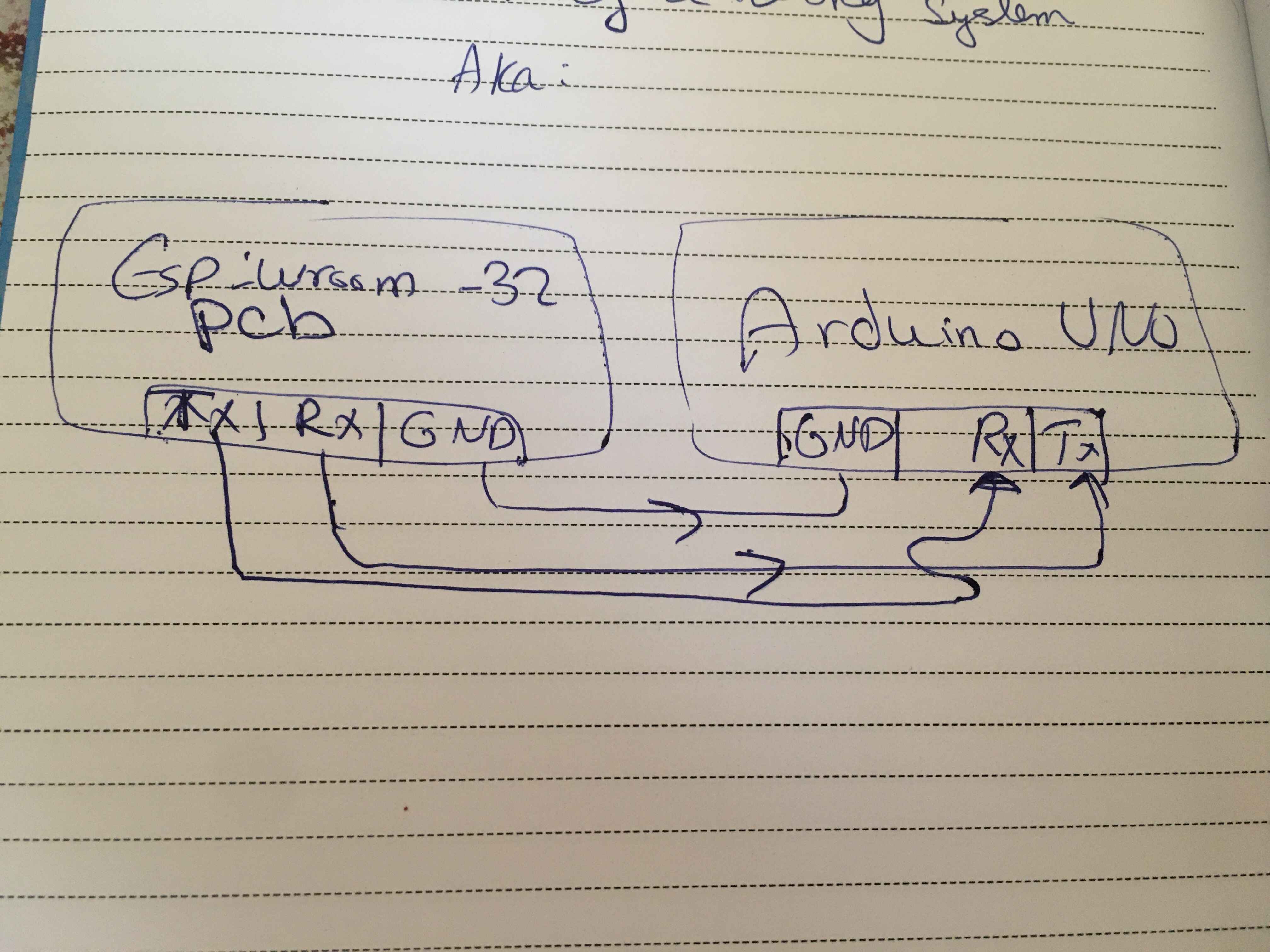
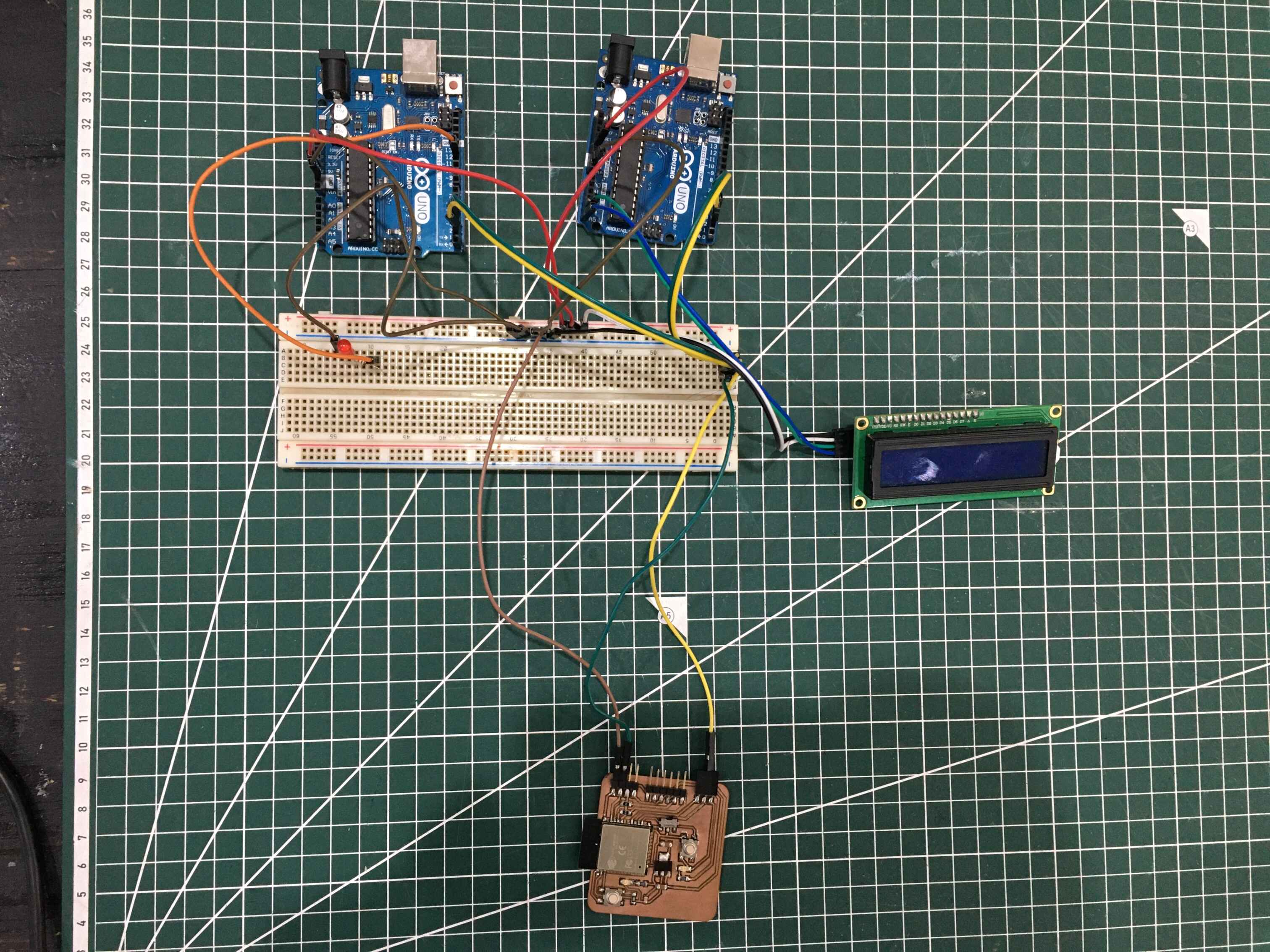
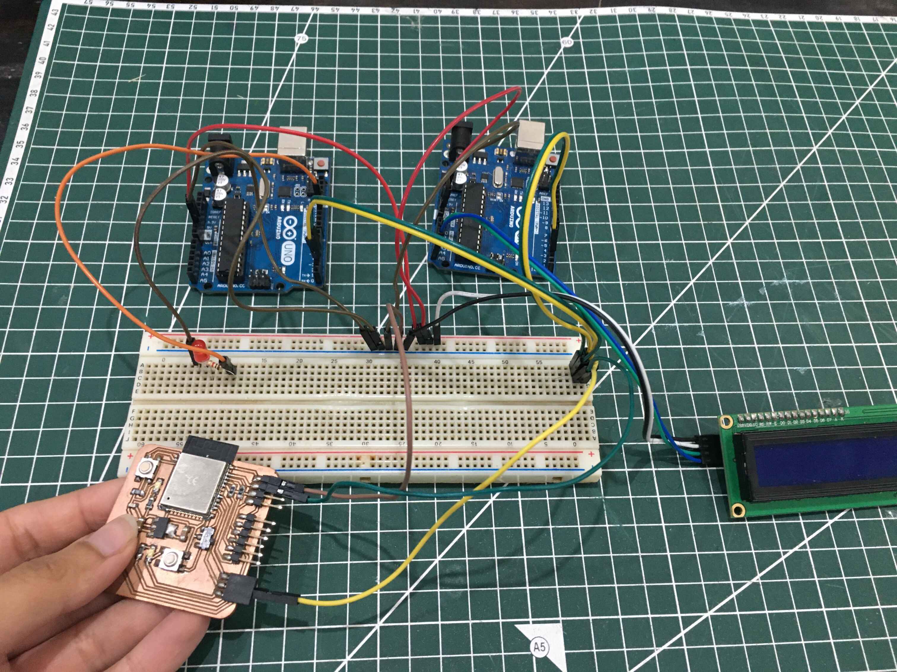
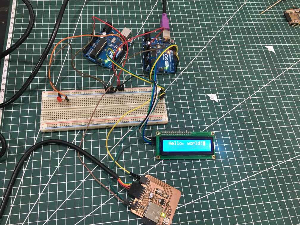
I'm going to use two arduinos that will only take orders from the esp32 pcb I made in week6. Each arduino will take an ID either "Slave A" or "Slave B". The ESP32 will be the master and send commands but not receive any. Arduino A is connected to an LED while Arduino B is connected to a LCD display.
The Wiring
- Arduino A: LED connected parallel with a 220 ohm resistor to pin number 12.
- Arduino A: Pin 2 Rx and Pin 3 TX both are connected series with the RX and TX pins on my board.
- Arduino B: LCD connected to pin number A5, A4, 5v, GND.
- Arduino B: Pin 2 Rx and Pin 3 TX both are connected series with the RX and TX pins on my board.
- Arduin A, Arduino B, ESP have common ground
.jpg)
.jpg)
The Logic
The Logic sounded easy send two characters one for ID and for the command. The Arduino checks if the first
character matches his ID then proceed to read the command. if the command is 0
digitalWrite(LED, LOW)
if not then HiGH and the same goes for the LCD but it shows "Hello, World " for command = 1 & blinks if 0.
I didn't know how to send two characters over the serial and make them readable. Until I stumbeled upon this masterpiece on Arduino forum.
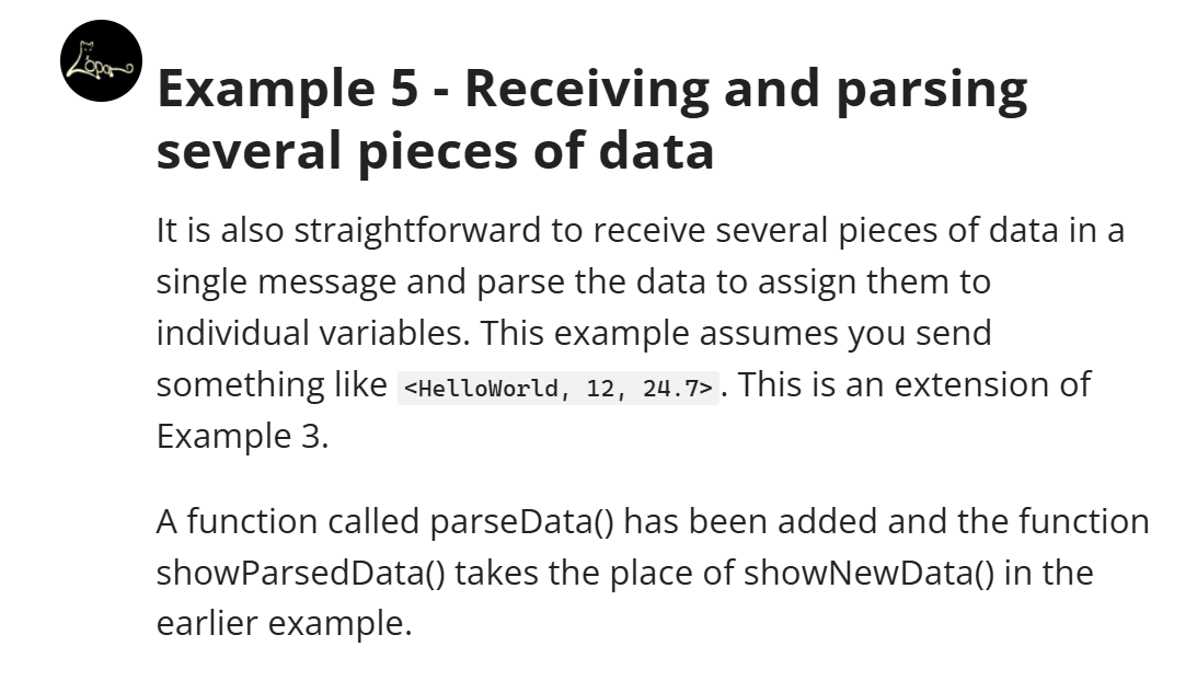
basically this code takes three character and parses through them and writes them on the serial. My code needs only two characters and some if conditions.
I tried controlling the led first then the lcd on Arduino "b" using my board then combining the two.
A video showcasing the LED Working.
A video showcasing the LCD Working.
The Challenge
After changing the code to suit my needs I tried to test it with the Arduino IDE serial monitor. I was able to send the two character being slavea or slaveb for identity and 0 or 1 for command marked between to less than and greater than signs. They received the message and performed the command when sent "1" both at the same time. This meant that the first condition regarding the ID wasn not being met.
A video showcasing what I mean
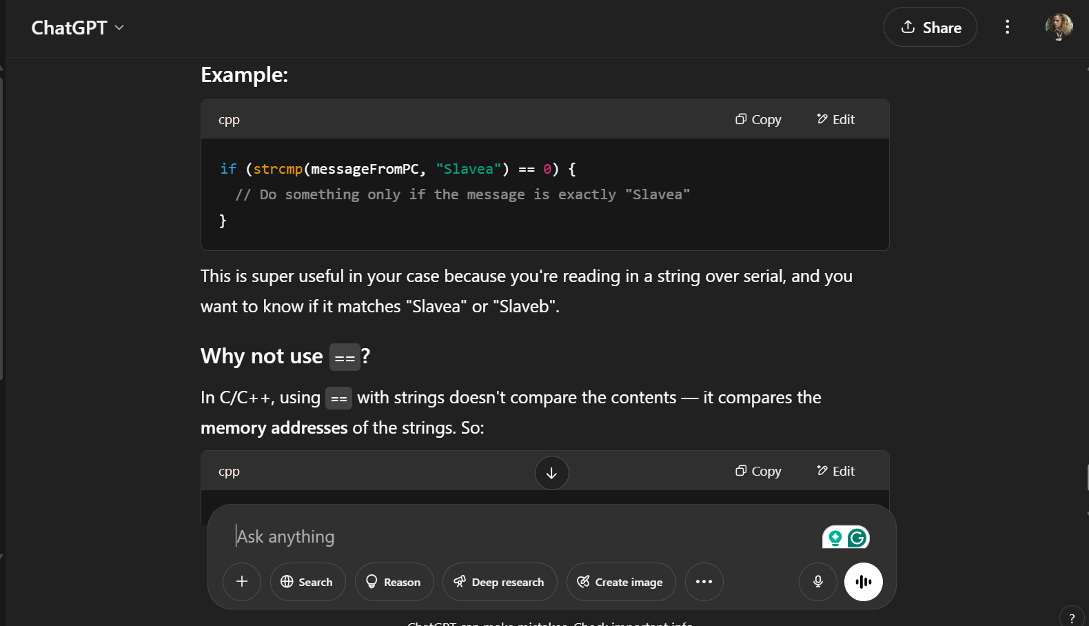
I didn't understand some function because they sounded hardcore C language so I asked ChatGPT what is the issue why is the logic not Working
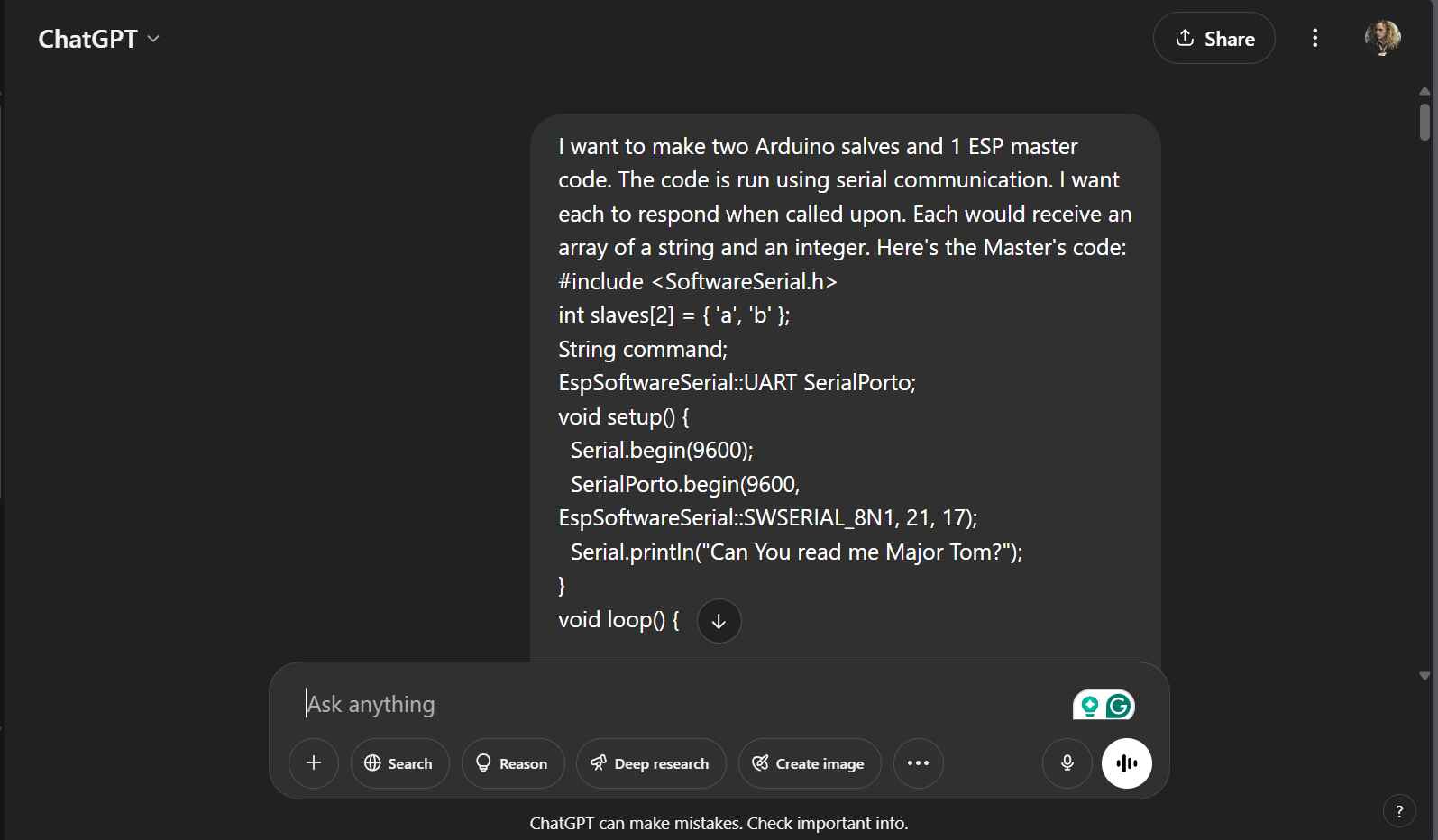
Here's my prompt
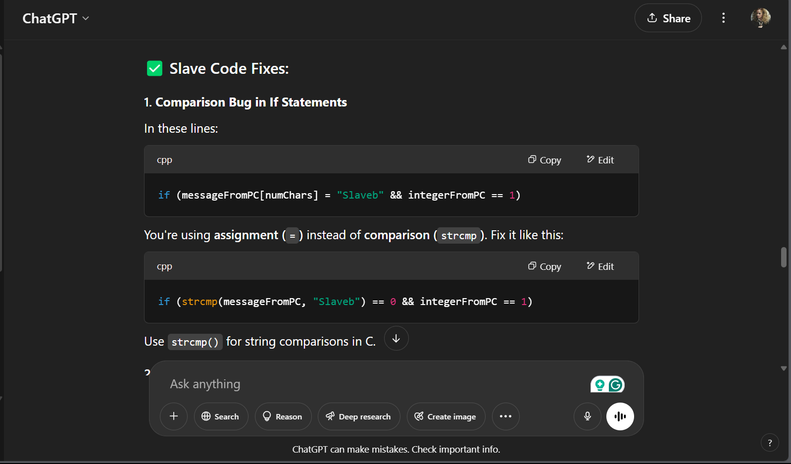
Here's his reply
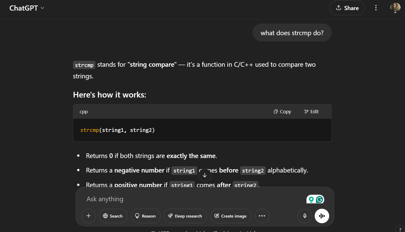
My mistake is the phrasing the if condition for the ID. I asked him further what is the difference between two lines.
The Output
The moment of truth! It WORKED!
ESP32 Master Code
#include SoftwareSerial.h>
int slaves[2] = { 'a', 'b' };
String command;
EspSoftwareSerial::UART SerialPorto;
void setup() {
Serial.begin(9600);
SerialPorto.begin(9600, EspSoftwareSerial::SWSERIAL_8N1, 21, 17);
Serial.println("Can You read me Major Tom?");
}
void loop() {

if (Serial.available()) {
command = Serial.readStringUntil('\n');
Serial.println(command);
SerialPorto.println(command);
} else {
// SerialPorto.print('0');
delay(10);
}
}
Arduino "a" Slave Code
#include SoftwareSerial.h>
int LED = 12;
const byte rxPin = 2;
const byte txPin = 3;
SoftwareSerial mySerial(rxPin, txPin);
const byte numChars = 32;
#define MY_NAME "Slavea"

char receivedChars[numChars];
char tempChars[numChars]; // temporary array for use when parsing
// variables to hold the parsed data
char messageFromPC[numChars] = { 0 };
int integerFromPC = 0;
boolean newData = false;
void setup() {
Serial.begin(9600);
mySerial.begin(9600);
pinMode(LED, OUTPUT);
}

void loop() {

recvWithStartEndMarkers();
if (newData == true) {
strcpy(tempChars, receivedChars);
// this temporary copy is necessary to protect the original data
// because strtok() used in parseData() replaces the commas with \0
parseData();
Serial.print("Message ");
Serial.println(messageFromPC);
Serial.print("Integer ");
Serial.println(integerFromPC);
if (strcmp(messageFromPC, MY_NAME) == 0 && integerFromPC == 1) {
digitalWrite(LED, HIGH);
} else

digitalWrite(LED, LOW);
}


newData = false;
}

//============

void recvWithStartEndMarkers() {
static boolean recvInProgress = false;
static byte ndx = 0;
char startMarker = '<'; char endMarker='>' ; char rc; while (mySerial.available()> 0 && newData == false) {
  rc = mySerial.read();

  if (recvInProgress == true) {
  if (rc != endMarker) {
  receivedChars[ndx] = rc;
  ndx++;
  if (ndx >= numChars) {
  ndx = numChars - 1;
  }
  } else {
  receivedChars[ndx] = '\0'; // terminate the string
  recvInProgress = false;
  ndx = 0;
  newData = true;
  }
  }

  else if (rc == startMarker) {
  recvInProgress = true;
  }
  }
  }

  //============

  void parseData() { // split the data into its parts
  char* strtokIndx; // this is used by strtok() as an index
  strtokIndx = strtok(tempChars, ","); // get the first part - the string
  strcpy(messageFromPC, strtokIndx); // copy it to messageFromPC

  strtokIndx = strtok(NULL, ","); // this continues where the previous call left off
  integerFromPC = atoi(strtokIndx); // convert this part to an integer
  }
Arduino "b" Slave Code
#include Wire.h>
#include LiquidCrystal_I2C.h>
LiquidCrystal_I2C lcd(0x27, 16, 2); // set the LCD address to 0x27 for a 16 chars and 2 line display
#include SoftwareSerial.h>
const byte rxPin = 2;
const byte txPin = 3;
#define MY_NAME "Slaveb"

SoftwareSerial mySerial(rxPin, txPin);
const byte numChars = 32;
char receivedChars[numChars];
char tempChars[numChars]; // temporary array for use when parsing
// variables to hold the parsed data
char messageFromPC[numChars] = { 0 };
int integerFromPC = 0;
boolean newData = false;
void setup() {
Serial.begin(9600);
mySerial.begin(9600);
lcd.init(); // initialize the lcd
lcd.backlight();
}

void loop() {

recvWithStartEndMarkers();
if (newData == true) {
strcpy(tempChars, receivedChars);
// this temporary copy is necessary to protect the original data
// because strtok() used in parseData() replaces the commas with \0
parseData();
Serial.print("Message ");
Serial.println(messageFromPC);
Serial.print("Integer ");
Serial.println(integerFromPC);
if (strcmp(messageFromPC, MY_NAME) == 0 && integerFromPC == 1) {
lcd.blink();
lcd.setCursor(1, 0);
lcd.print("Hello, world!");
Serial.print("ِAction");
} else if (messageFromPC[numChars] = "Slavea" && integerFromPC == 1) {
lcd.clear();
} else if (messageFromPC[numChars] = "Slavea" && integerFromPC == 0) {
lcd.clear();
}


newData = false;
}
}

void recvWithStartEndMarkers() {
static boolean recvInProgress = false;
static byte ndx = 0;
char startMarker = '<'; char endMarker='>' ; char rc; while (mySerial.available()> 0 && newData == false) {
  rc = mySerial.read();

  if (recvInProgress == true) {
  if (rc != endMarker) {
  receivedChars[ndx] = rc;
  ndx++;
  if (ndx >= numChars) {
  ndx = numChars - 1;
  }
  } else {
  receivedChars[ndx] = '\0'; // terminate the string
  recvInProgress = false;
  ndx = 0;
  newData = true;
  }
  }

  else if (rc == startMarker) {
  recvInProgress = true;
  }
  }
  }

  void parseData() { // split the data into its parts
  char* strtokIndx; // this is used by strtok() as an index
  strtokIndx = strtok(tempChars, ","); // get the first part - the string
  strcpy(messageFromPC, strtokIndx); // copy it to messageFromPC

  strtokIndx = strtok(NULL, ","); // this continues where the previous call left off
  integerFromPC = atoi(strtokIndx); // convert this part to an integer
  }