Week_9 Assignments
- Group assignment:
- Individual assignment
- Resistive force Sensor
- Capacitive touch sensor
Our group assignment was to get reading from a sensor and then display/plot its analog and digital readings.
We needed to add a sensor to our Microcontroller board and get readings from it. I used these sensors and made the a PCB:
Group assignment
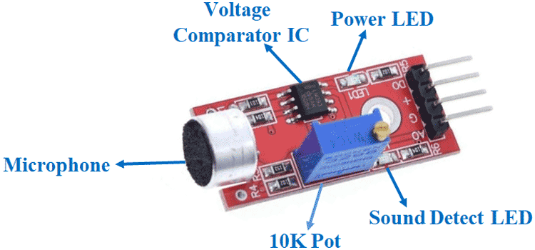
For analog readings plotting. We used a microphone module that had 4 pins VCC, GND, A0 and D0 and used A0 pin. We used the analog input pin according to the arduino and got the reading then used Arduino IDE Serial plotter to display the results.
Code:
      int sensorpin = D0;
      int analogreading;

      void setup()
      {
        Serial.begin(115200);
        pinMode(sensorpin, INPUT);
      }

      void loop ()
      {
        analogreading = analogRead(sensorpin);
        Serial.println(analogreading);
      }
Then we modified the code to act like a digital input. Using if condition to make a threshold for the values.
Code:
    int sensorpin = D0;
    int analogreading;


    void setup()
    {
      Serial.begin(115200);
      pinMode(A0, INPUT);
    }
    void loop()
    {
      int microphone = 0;

      for (int x=0; x < 50; x++)
      {
        if (analogRead (A0) > 2000)
        {
          Serial.println(1);
          //break;
        }
        delay(1);
      }

        Serial.println(0);
    }
Individual assignment
Force sensing resostor
This sensor working principle is build upon the change of the resistance caused by forced deformation/pressure. I tested it in Tinkercad to see how much resistance needed to be connected to this sensor to act like a voltage divider first resistor and the sensor is the second one that changes and causes the output voltage to change.
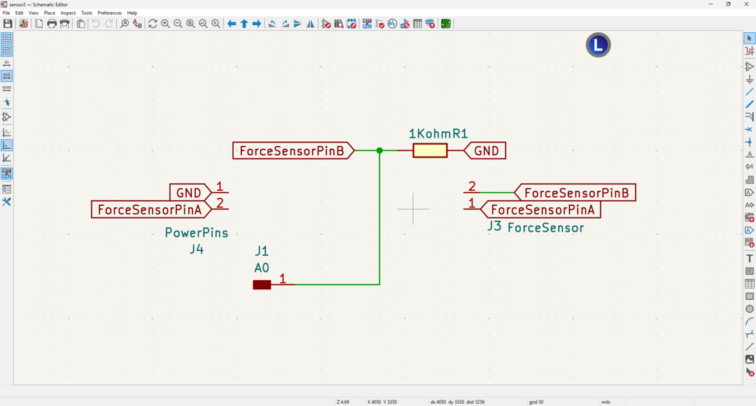
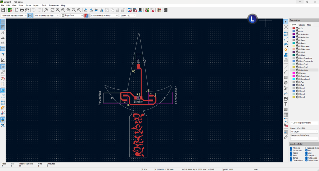
I found that a 1K ohm resistor got me a wide range of readings in real life. So I began to design my PCB for the resistive sensor. I made the sensor detachable to make this PCB modular for any resistive sensor (where its range depends on the fixed 1Kohm resistance).
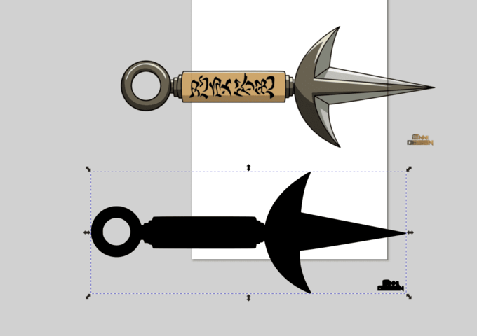
Also I didn't like it to be a rectangular shape and I wanted to be cool ^^. so I downloaded a PNG of the famous Kunai of Minato Namekazi from the anime series Naruto Shippuden which I am a big fan of.

- I started the workfolw of designing a pcb with drawing the schematic.
- I used inkscape to bitmap the outlines and the writings.
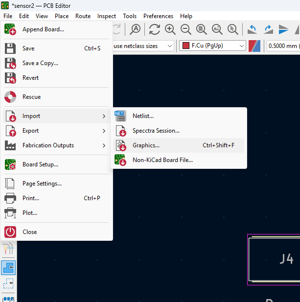
- Then I added the SVG files to Kicad and I exported the outline and the writings seprately. then imported the to the PCB editor in Kicad. using Import-> Graphic
- Then I edited the placement of the components.
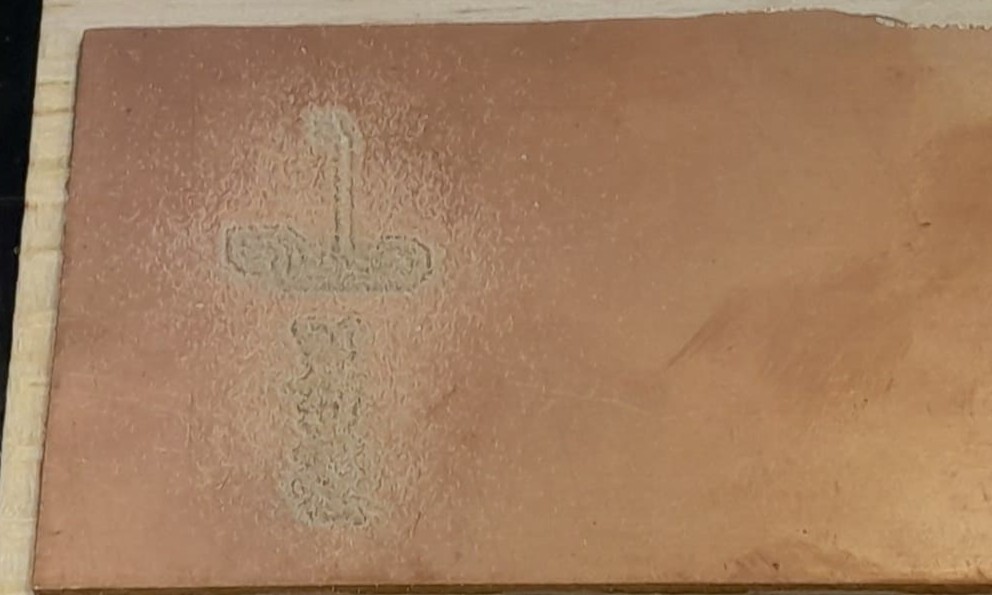
- Then I fabricated it. (More info on the fabrication will be discussed below).
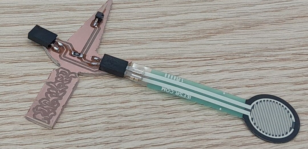
- I soldered the components and connected the sensor.
- I tested it using Arduino IDE
Code:
        int forcesensorpin = A0;
        int adcreadings;

        void setup()
        {
          Serial.begin(115200);
          pinMode(forcesensorpin, INPUT);
        }
        void loop ()
        {
          adcreadings = analogRead(forcesensorpin);
          Serial.println(adcreadings);
          delay(10);
        }
Code:
    int forcesensorpin = A0;
    int adcreadings;
    int light;
    int led = D2;

    void setup()
    {
      Serial.begin(115200);
      pinMode(forcesensorpin, INPUT);
      pinMode(led, OUTPUT);

    }
    void loop ()
    {
      adcreadings = analogRead(forcesensorpin);
      light = map(adcreadings, 0, 4095, 0, 4095);
      analogWrite(led, light);
      Serial.println(adcreadings);
      delay(10);
    }
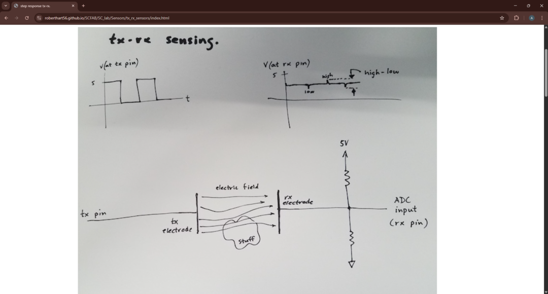
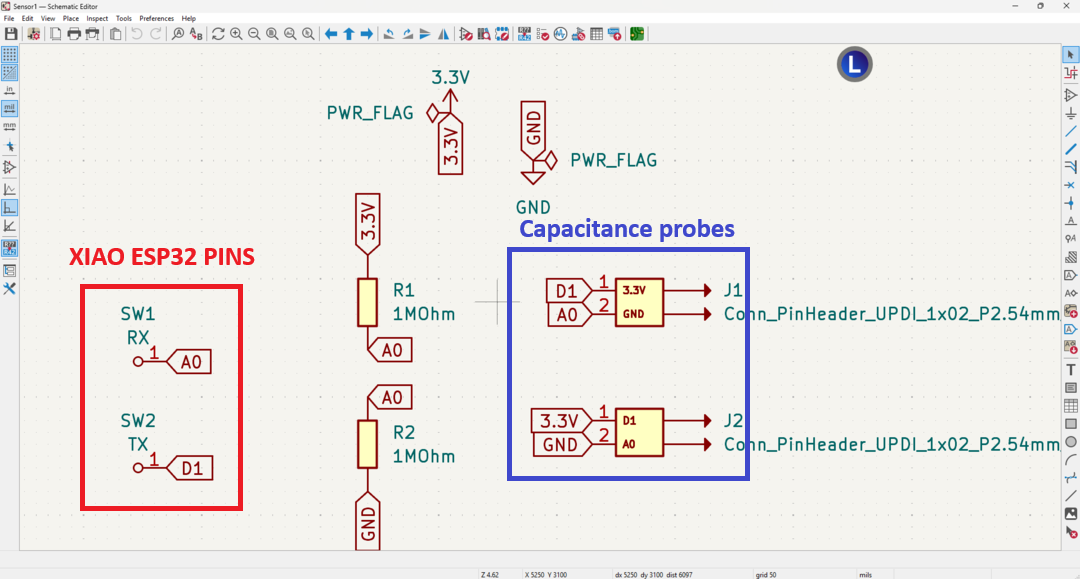
Capacitive Sensor step response
I followed the following tutorial to make the step response. The capacitance varies upon the distance and the type of the dielectric material. What happens is that I connet one of the capacitive probes to a digital pin in my Xiao ESP32 and outputs on it an alternative digital signal between HIGH and LOW which charges and discharges the probe. While this happens the other probe or terminal of the capacitive sensor is connected to an analog pin to read a change in the voltage across the terminals. The resistors connected to the pin is to reduce the noise and unwanted signals.
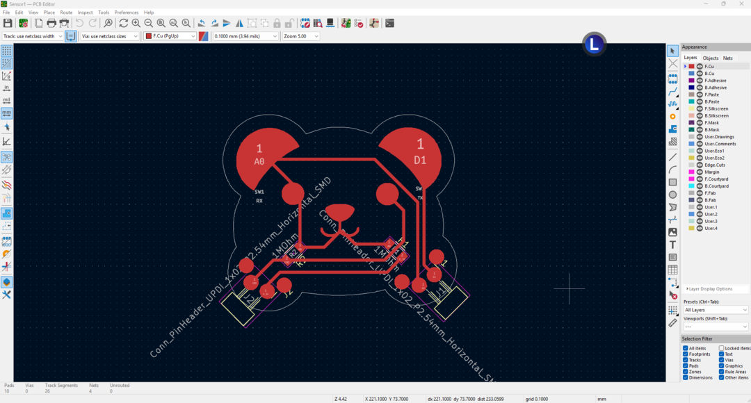
Then I design the schematic on kicad.
I wanted also to make a different shape other than a rectangular shape so I used inkscape to make it like a panda and its ears are the probes.

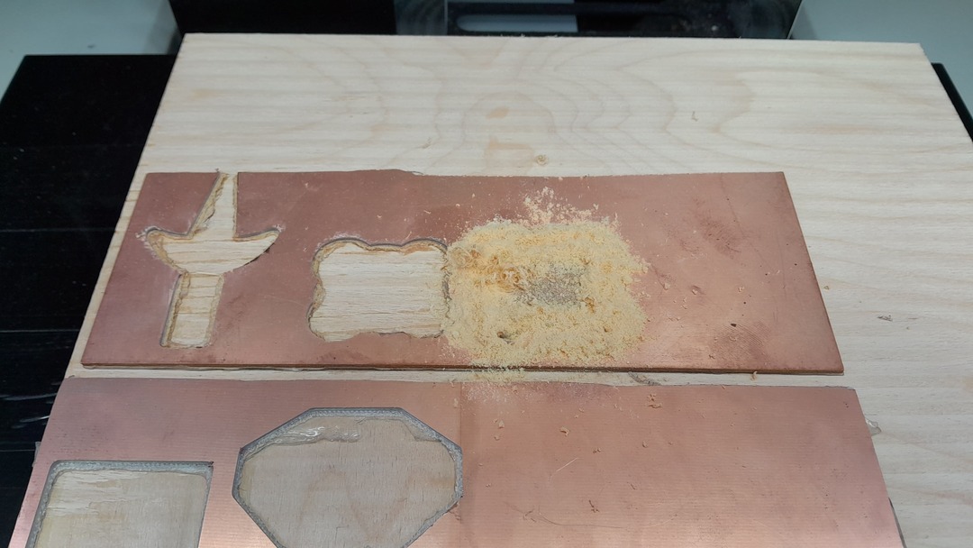
Then I fabricated it. (More info on the fabrication will be discussed below).:
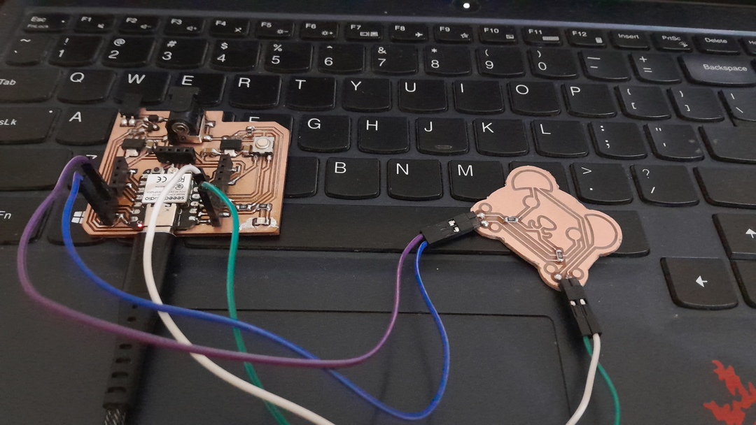
The I tested the PCB using the code provided by the tutorial.
Code:
    //rx_tx02  Robert Hart Mar 2019.
    //  Program to use transmit-receive across space between two conductors.
    //  One conductor attached to pin4, one to A0
    //
    //  Optionally, two resistors (1 MOhm or greater) can be placed between 5V and GND, with
    //  the signal connected between them so that the steady-state voltage is 2.5 Volts.
    //
    //  Signal varies with electric field coupling between conductors, and can
    //  be used to measure many things related to position, overlap, and intervening material
    //  between the two conductors.

        int read_high;
        int read_low;
        int diff;
        long int sum;
        int threshold = 250;
        int N_samples = 300;    //Number of samples to take.  Larger number slows it down, but reduces scatter.

        int analog_pin = A0;
        int tx_pin = D1;

        int x =0;

        int count = 0;
        void setup() {
        pinMode(4,OUTPUT);      //Pin 4 provides the voltage step
        Serial.begin(115200);
        }

        void loop() {

        sum = 0;

        for (int i = 0; i < N_samples; i++){
          digitalWrite(tx_pin,HIGH);              //Step the voltage high on conductor 1.
          read_high = analogRead(analog_pin);        //Measure response of conductor 2.
          delayMicroseconds(100);            //Delay to reach steady state.
          digitalWrite(tx_pin,LOW);               //Step the voltage to zero on conductor 1.
          read_low = analogRead(analog_pin);         //Measure response of conductor 2.
          diff = read_high - read_low;       //desired answer is the difference between high and low.
          sum += diff;                       //Sums up N_samples of these measurements.
        }
        Serial.println(sum);


        // if (abs(sum)> threshold)
        // {
        //   x= 1;

        //   Serial.println(x);
        // }
        // else {
        //   x= 0;
        // Serial.println(x);
        // }


        delay(10);

        }
Obviously the sensor is not stable and need refining. I think I should have made the probes bigger and refined the code abit.
Fabrication and using Modela MDX50
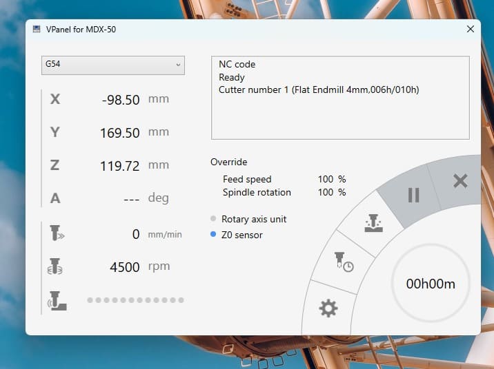
I was so excited using this beautiful machine ^^. Modela MDX50 is great machine that has a tool magazine that I will use and also has an optional rotary axis that I am planning to use in the wild card week. It has great safety features that it won't do anything unless the door is closed and the drawer is closed. A great feature is that it can handle both rml filas and nc files.
I started by chooseing the V bit for milling the traces which is tool number 1 (I arranged my tools to be like this: tool 1 is the V bit for traces, tool 2 is the 0.8 dril bit for holes and tool 3 1.2mm bit to cut the outline.)
Then I started zero-ing the X and Y axis:
A great feature in the Modela MDX50 is that it has a Z-zero sensign sensor that is great to use instead of handling this process manually.
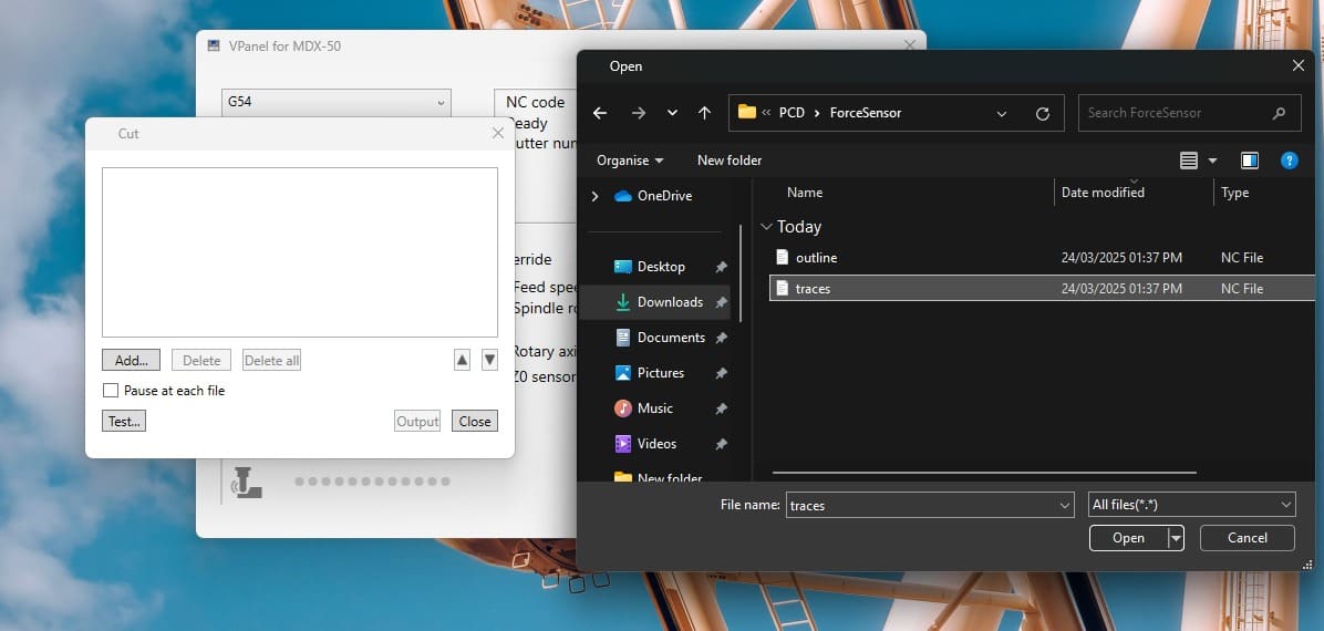
and finally I began to mill my PCB. I used Vpanel to upload the .nc files to the machine.
I wne to the cut icon and then deleted all the previous operations and the added the file I want then I hit Output.
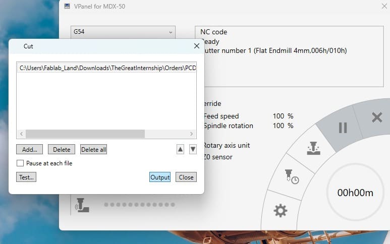
Finlly the machine starts: