Week_7 Assignments
- Group assignment:
- Individual assignment
Our group assignment was to characterize the properties of the milling process. We tested runout, fixturing and some toolpaths.
Let's just we need to design and mill something BIG ^^.
Group assignment
As for my role in the group assignment I tested the runout and the cross joint using T-bone. We were encoraged to use ArtCAM but for some reason I had some errors installing it so I used Fusion manufacturing workspace.
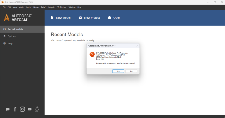
I ignored this massage at first and made my way through the settings but after I finished all the steps of setting up my toolpathes when I needed to save the toolpathes as .nc file I didn't find the post processors.
Testing
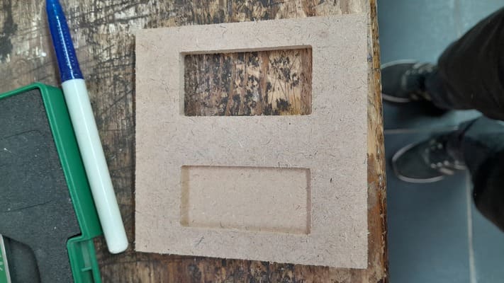
For testing the runout I turned to Autodesk Fusion 360 to go through the CAM workflow instead of Artcam. So I designed a simple workpiece that contains three profiles and have a thickness of 6mm:
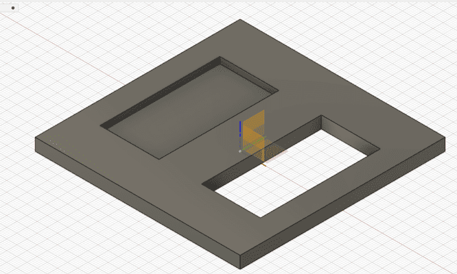
- A profile is to be made a pocket with depth of 3mm.
- A profile is to be cut all the way.
- A profile for the outline.
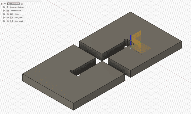
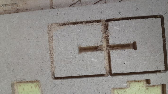
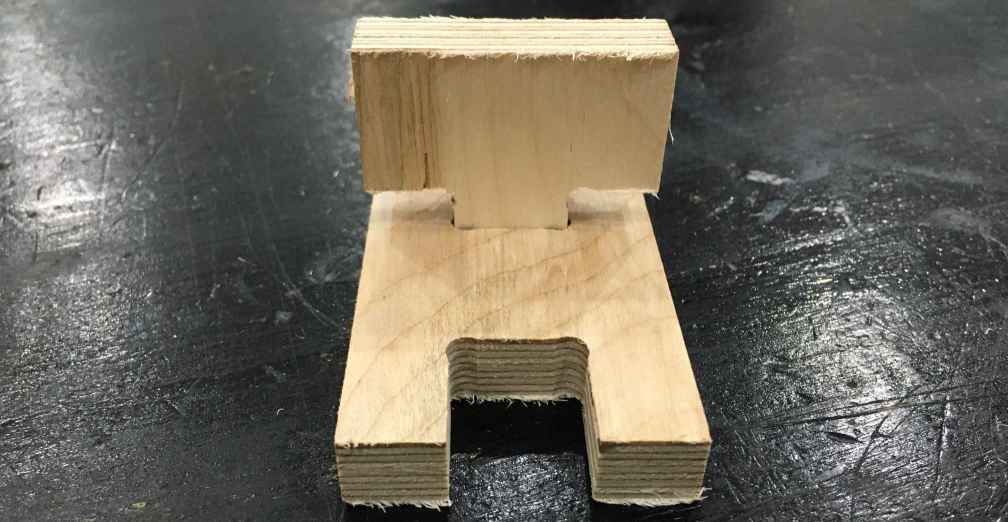
As for the cross T-bone joint I designed in also in fusion and used the manufacturing workspace to output the .nc files that contain the g.code.
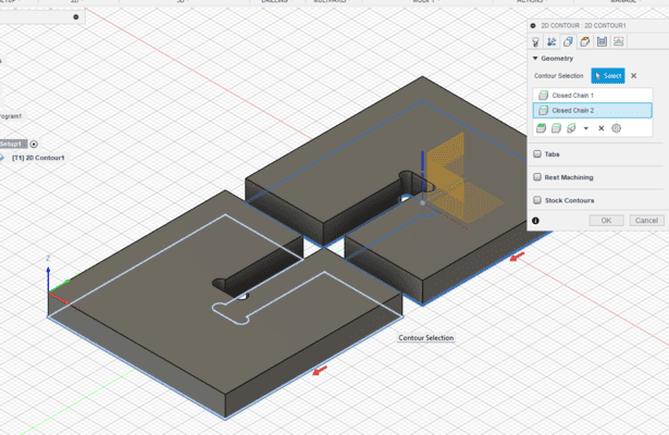
Designing using the T-bone shape is used in the milling process when needed to cut parts and these parts are to be assembled together. The problem is when the milling bit mills the right angle it makes it round (makes fillets). and that does not fit nicely with the right angle of the second part like so.
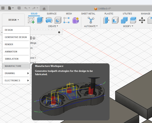
After the design I move to the Manufacturing Workspace in Fusion and here is how I managed to get the .nc files or the toolpathes.
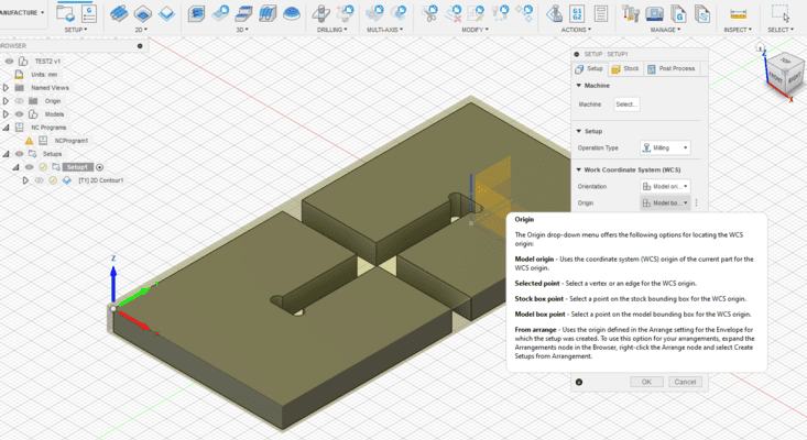
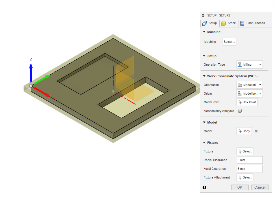
- First I prepared the setup for the manufacture. This where you add your machine if you have it, edit up your stock, select the operation you will make which here is "milling" and define the origin of the stock.
- After that we need to choose the processes to be made along with some setting like the cutting tool, step over and multiple depth . Like for the runout test there are 2 main processes:
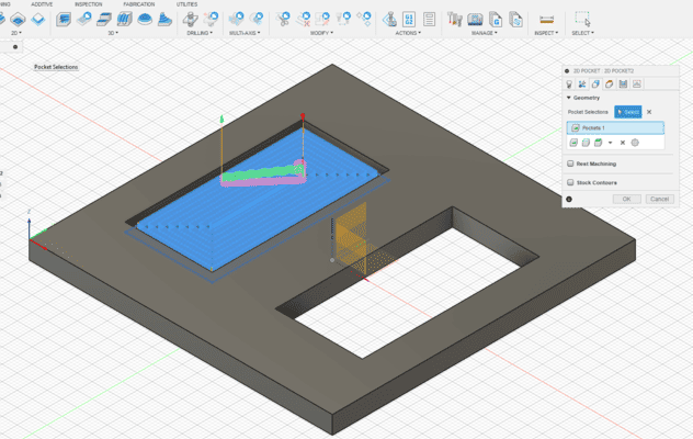
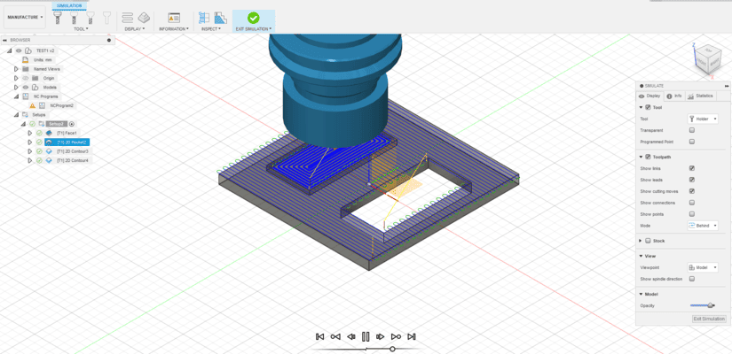
- 2D Pocket: this where we want to cut/scan a depth of 3mm.
- 2D Contour: this is for the inside all the way cut and the cutting of the outline.
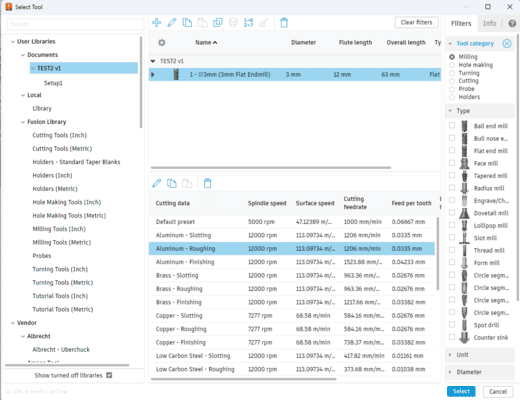
- I used a 3mm endmill for the cutting tool. and chose the default setting for the rough aluminum profile. it did great with the 6mm MDF.
- For the step over I choose a value of 1.8mm.
- For the multiple depth I allowed it and made the steps in 1mm.
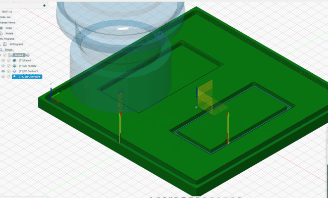
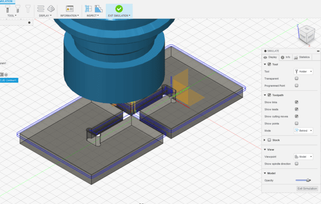
- After i done that I simulated the toolpathes.
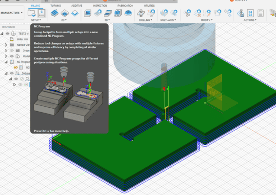
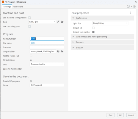
- Now after the simulation and making sure that everything is okay ^^. I exported/ posted the .nc files using the g.code icon.
- Then choose the operation to include in the g code file and the post processor that is compatible with the machine.
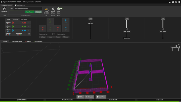
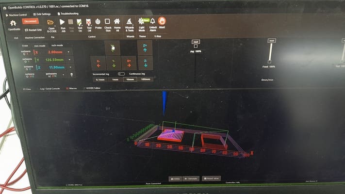
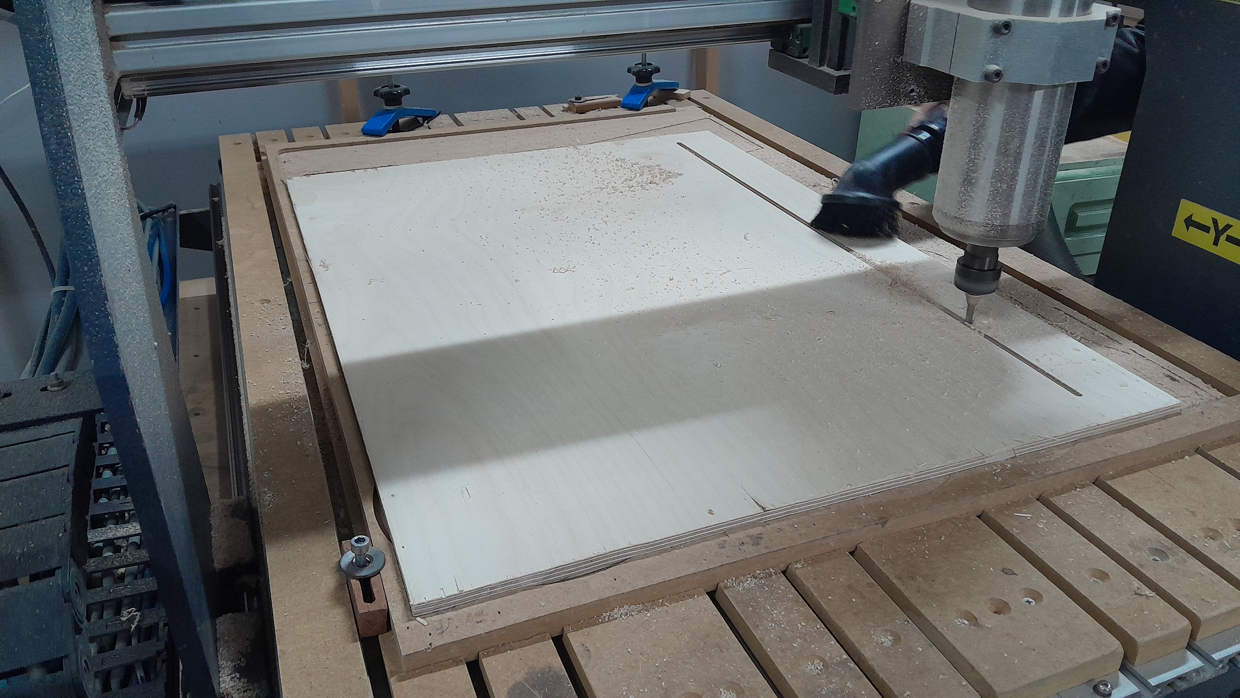
- then I used OpenBiulds to control China Router via USB cable I fixed the workpiece on top of the sucrificial piece. Then Homed the x and y axes and then turned on the spindle and carefully heard the machine until a buzzing sound started that is z zero.
- Finally I Hit Run job ^^.
As for the T-bone cross joint the process are only one process which is 2D Contouring.
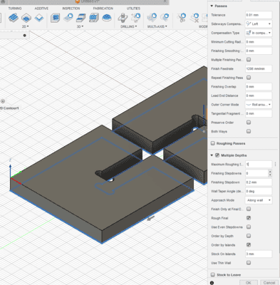
I used the following setting foreachg of these processes:
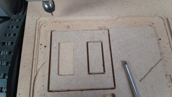
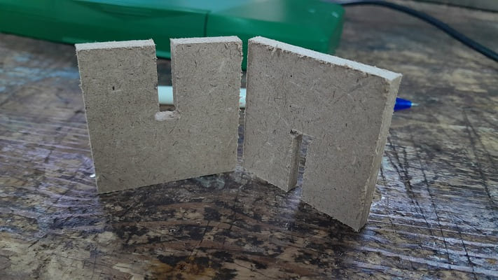
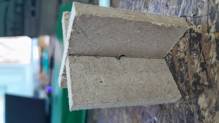
Fabricated parts
Conclusion
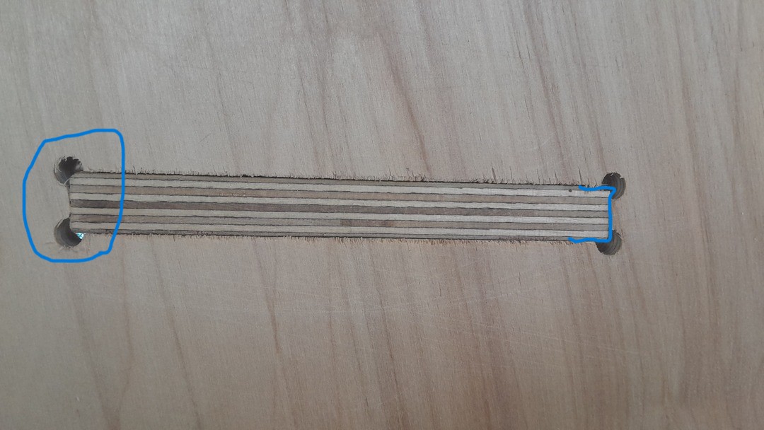
I have found that the runout on the machine is close to 0.02mm. using the test done.
As mentioned this test we ran on the China Router machine in our lab but not the actual machine we used in our Individual assignment.
With the same steps for designing (tab slot joint) and getting the gcode but here not a generic gcode post processor it is Mach3 post processor is needed.
The machine is Malky MR96 Router. The machine had a working area of 90cm by 60cm.
The machined parts:
The runout for this machine is around 0.08.
Individual assignment
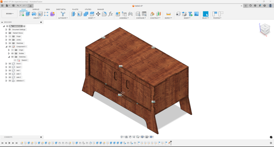
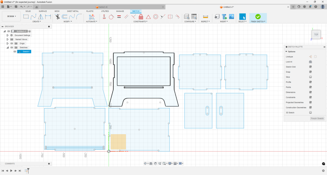
For my assignment I design a TV table with a drawer to store
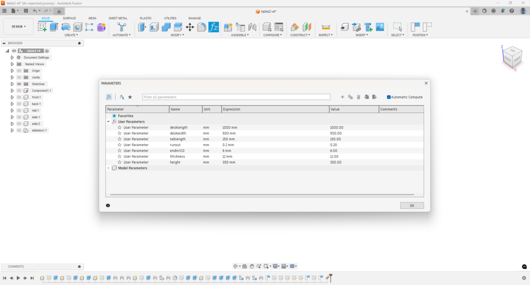
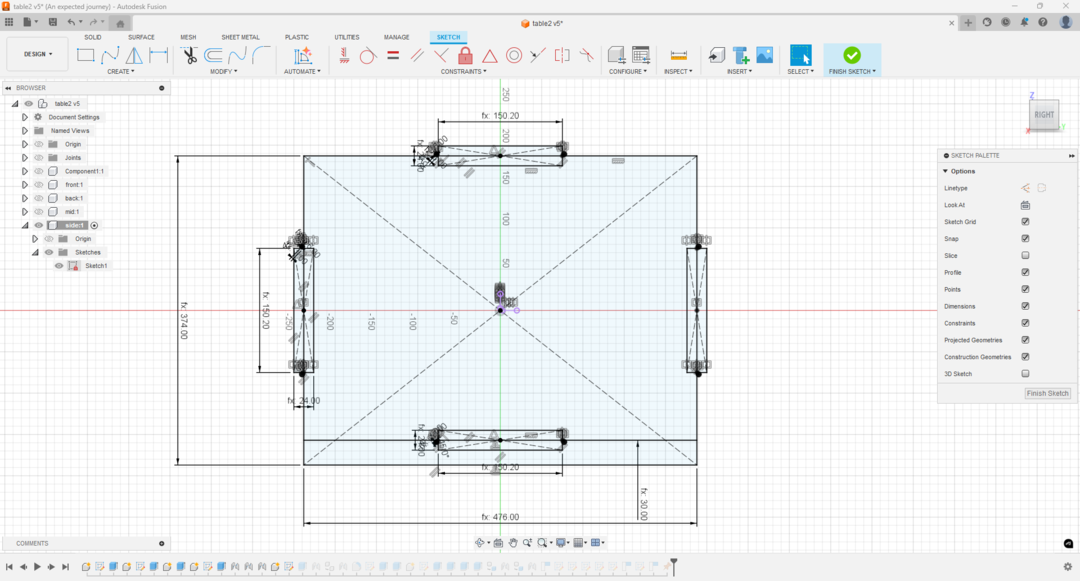
- I started to design in fusion 360. I laid down my parameters
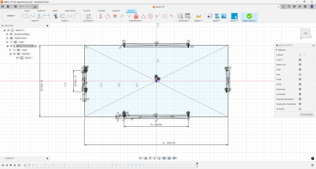
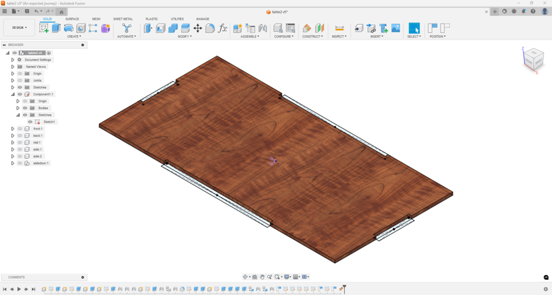
- Then started with drawing the base and the top pieces
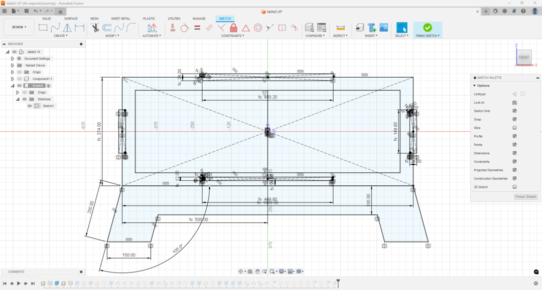
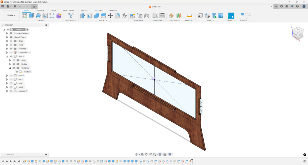
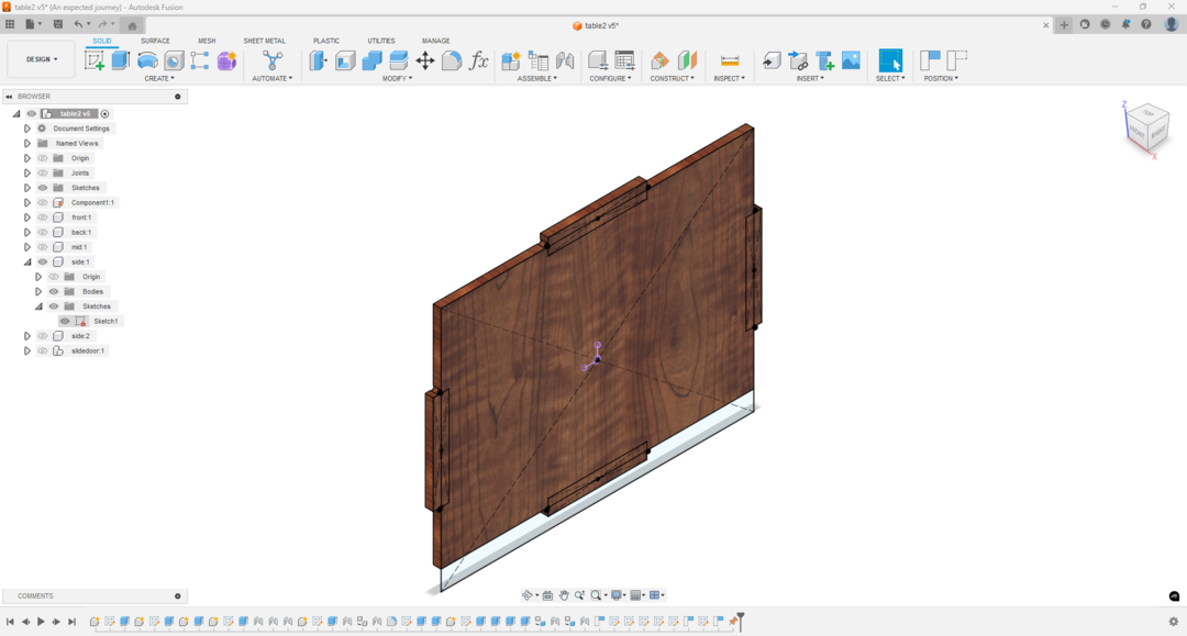
- Then designed the front and the back pieces the angle the legs took was intuitive not based on somethingbut I think it worked out great.
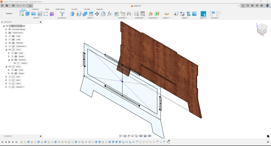
- I tried to keep my design symmetric or mirrored so the back is the same as the front except for the opening like so.
- I moved to the sides
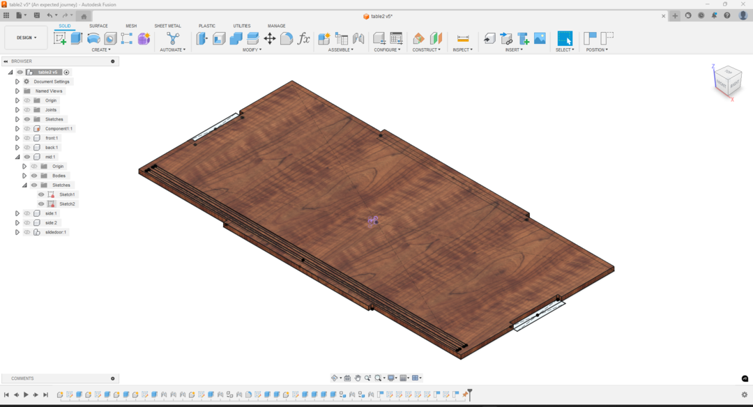
- I added the groves for the drawer doors to slide in. I added them into the top and the bottom/base parts.
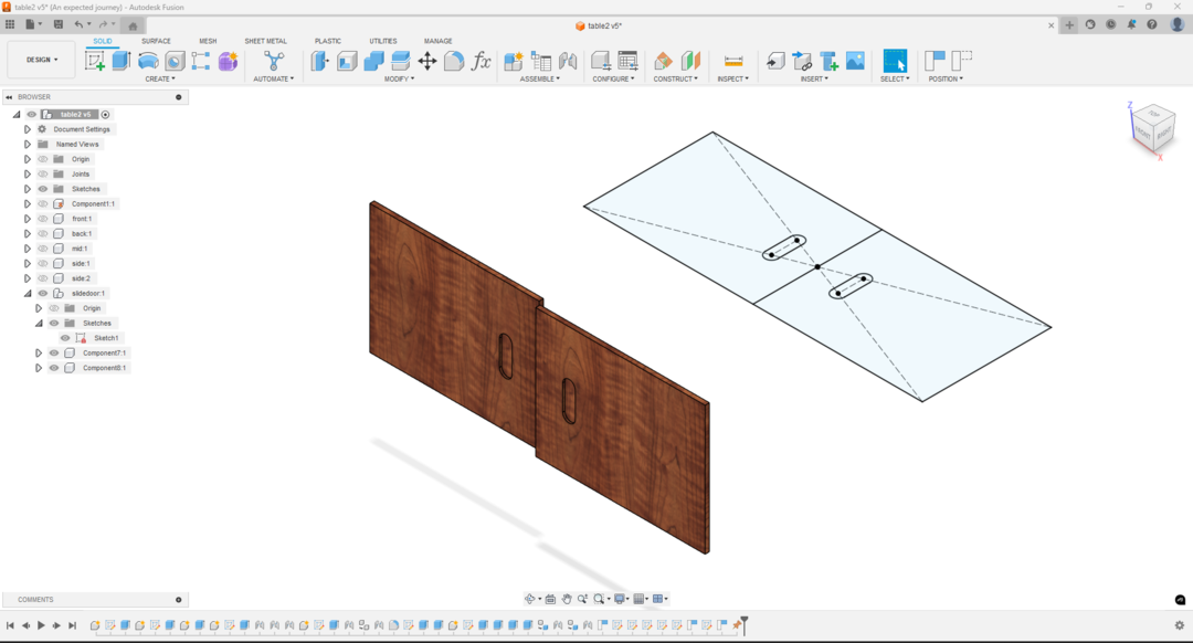
- I designed the drawer doors
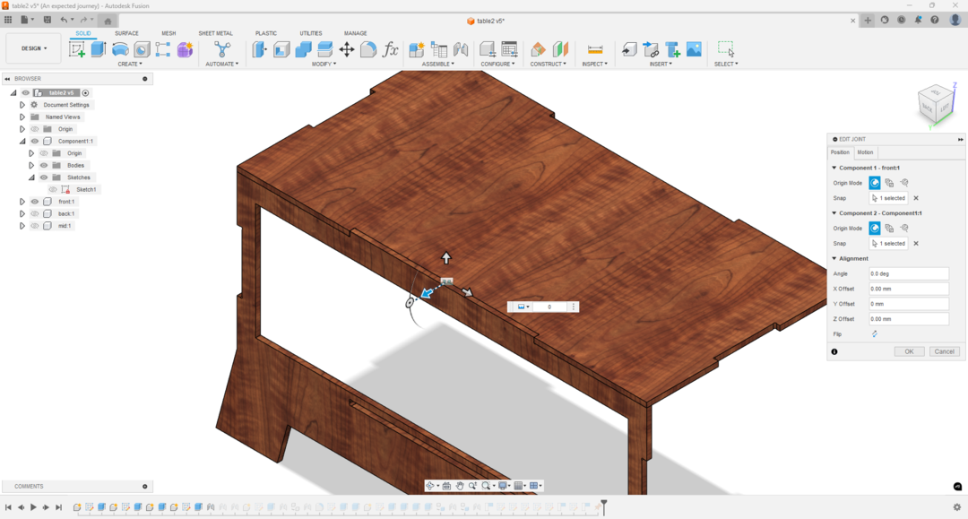
- I used the joint function to joint the pieces together (a rigid motion except for the drawer doors i made them slides.)
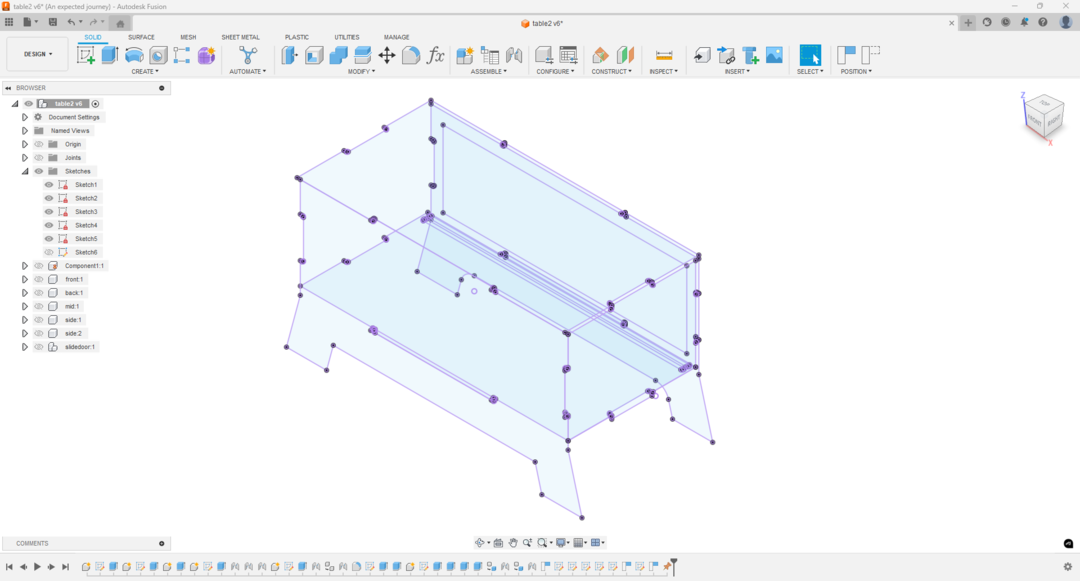
- Then I projected each component serface to use as the final dxf file.
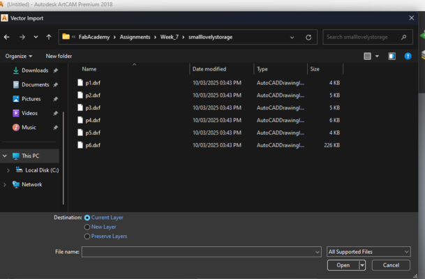
- After that I saved each sketch as DXf file.
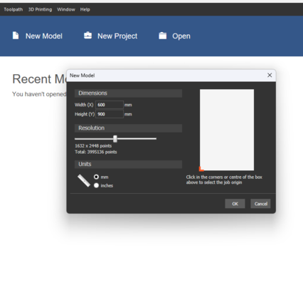
- I used Artcam to make the toolpathes and get the g.code files.
- I imported each part into Artcam.
- I used transform to fit the part on the workpiece.
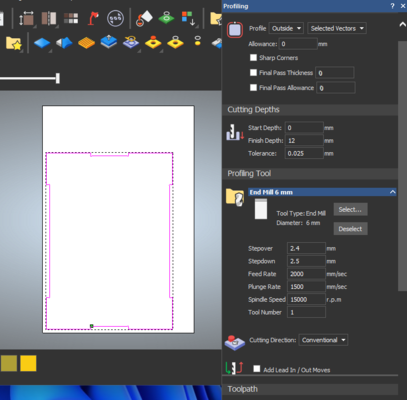
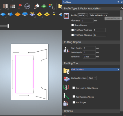
- Then I selected the areas and the toolpath to define process of cutting and its settings.
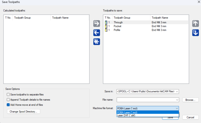
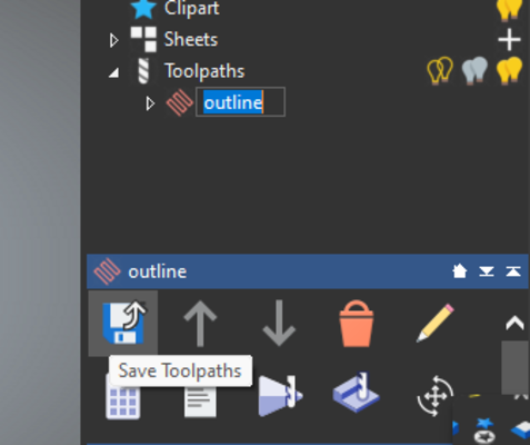
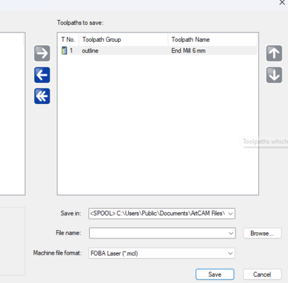
- After entering these settings ans calculate the toolpath. I save the toolpath choosing the right postprocessor for the machine in this case Mach3.
- Then I took the gcode files wen to the machine.
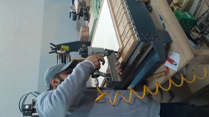
- I pinned the workpiece on the machine
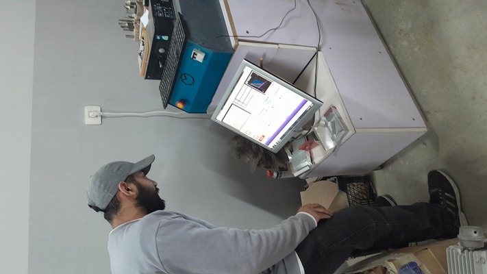
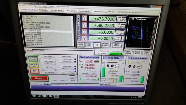
- After that I went to the machine controller hit the button related to zero all the x, y, and z axes. Then I hit run cycle.
- After That I got the parts I sanded them tried to test the fitting and the fit qiute nice ^^.
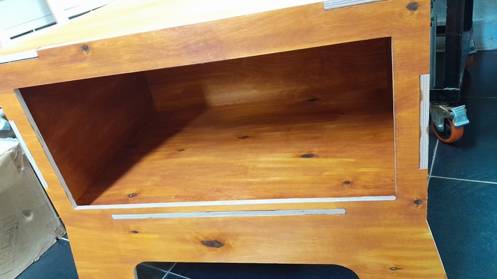
- Then I realized I made a great mistake that I didn't make the grove in the top part.
The dxf file I saved it had only the one of the top/bottom part had the groves in it.
- I stained the pieces with orange like colour.
- So for the mean time I make it like an normally open (LOL) drawer ^^. I flipped the bottom to get a whole working assembly
Settings like profile, finish depth, tool diameter, feed rate, plunge rate adding bridges or not and finally the material definition.
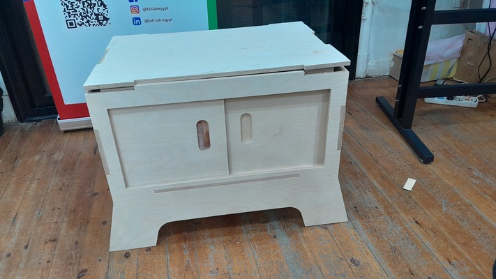
As you can see that the doors lifts up for the missing groves.