Week_4 Assignments
This week I will explore more about microcontrollers architecture, capabilities and more about programming them. I have experience using Arduino uno , Arduino nano, Arduino mega, Esp8266 mini, Esp8266 Node Mcu and Esp 32 dev board programming them using rduino IDE. this week I want to program them using micropython not arduino c and also use platformIO IDE extension in VScode.
This week I have a group assignment and individual assignment:- Group assignment
- We need to explore as many embedded systems hardware capabilities, software toolchain to program them and compare them according to the mentioned points
- Individual assignment
- Walk through a datasheet of a microcontroller.
- Write a program for a microcontroller and simulate its operation. Design it to interact meaning it should have input and output devices and communication.
Group assignment
We discussed the difference between Von Neumann and Harvard MCUs structures and the main diifference is that the exiestance of a shared memory in between the program data and instruction data in the Von Neumann archeticture on the other hand the harvard archeticture has a seperate memory for each data.
We also walked through the datasheet of two different MCUs: ATmega328p and ESP32. we found that the ESP32 has great capabilities when compared with ATmega328p as it has more Flash memory, more EEPROM memory, has more communication protocols and has a built-in wifi and bluetooth prepherals.
We talked about different toolchains to deal with each MCUs like we can use AVRdude to configure the atmega328p and to upload the code using its hex file. Also for atmega328p we can use AVRstudio to convert the code into hex file "machine language". We found that the easiest way to program an ATmega328p MCU is to use Arduino IDE as it has all the toolchains integrated in it.
As for the ESP 32 the easiest way is to use Arduino IDE but if you want to do deeper and use something like AVRdude you can use ESP IDF.
Individual assignment
Simulations
I have experience using Tinkercad as my go to Arduino programming simulator and playground so I tried Wokwi as the simulation for using a board like Xiao Esp32 C3.
I used Xiao Esp 32 C3 as the MCU. I used a potentiometer as an input and the output is an OLED display using I2C protocol to communicate with the Xiao board.
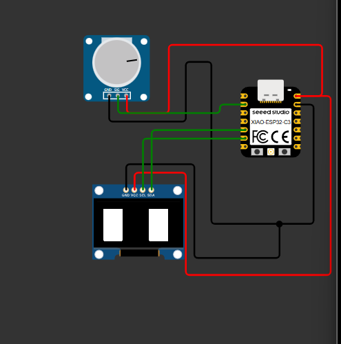
"Circuit Wiring"
We need to know the pinout of the Xiao board and how it is like:
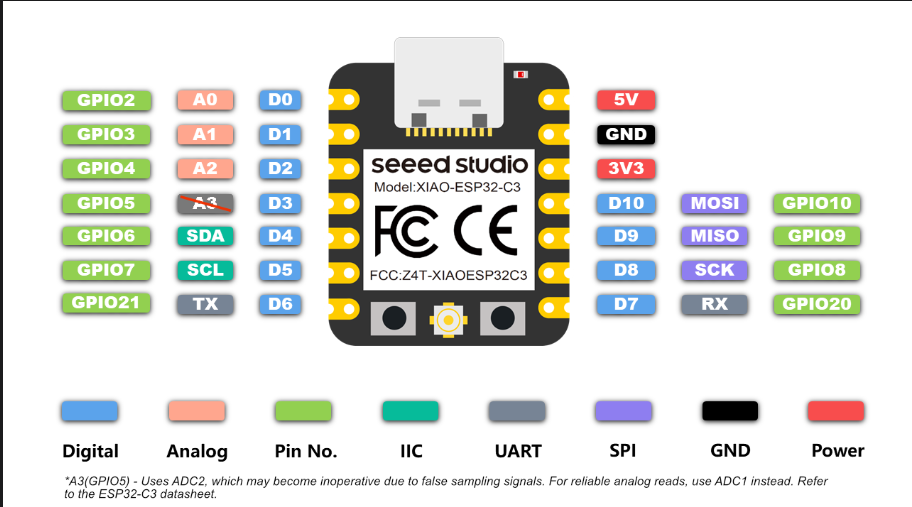
- First I connected the potentiometer to the Xiao board. The potentiometer has 3 pins "GND, Signal and VCC". I connected the GND to the GND of the Xiao board and the same with the VCC pin to the 5V pin in the Xiao board and finally the signal pin connected it to the D1 pin.
- I connected the OLED display to the Xioa. The OLED display has 4 pins "VCC, GND, SCL and SDA". The connection is straight forward the VCC with the 5V pin in the Xiao, the GND with the GND, the SCL pin is conned pin D5 as shown int the pinout diagram and the SDA pin is connected to D4 pin.
The wiring is a piece of cake ^^.
And just like that we finished wiring the components let's move to the programming where I used this tutorial to learn how to program the I2C OLED display with an ESP 32 board
"Coding ^^"
#include <SPI.h>
#include <Wire.h>
#include <Adafruit_GFX.h>
#include <Adafruit_SSD1306.h>

#define SCREEN_WIDTH 128
#define SCREEN_HEIGHT 64

Adafruit_SSD1306 display(SCREEN_WIDTH, SCREEN_HEIGHT, &Wire, -1);

int potpin = D1;
int potvalue;

void setup () {
  Serial.begin(115200);

  if(!display.begin(SSD1306_SWITCHCAPVCC, 0x3C)) {
    Serial.println(F("SSD1306 allocation failed"));
    for(;;);
  }

  delay(2000);
  display.clearDisplay();
}

void loop () {
  potvalue = analogRead(potpin);
  Serial.println(potvalue);

  if (potvalue >= 0 && potvalue < 2040) {
    display.clearDisplay();
    display.fillRoundRect(10, 40, 30, 20, 2, WHITE);
    display.fillRoundRect(80, 40, 30, 20, 2, WHITE);
    display.display();
  } else {
    display.clearDisplay();
    display.fillRoundRect(10, 10, 30, 50, 2, WHITE);
    display.fillRoundRect(80, 10, 30, 50, 2, WHITE);
    display.display();
  }
}
- Started the code by including the libraries used buy the OLED I2C display
  #include <SPI.h>
  #include <Wire.h>
  #include <Adafruit_GFX.h>
  #include <Adafruit_SSD1306.h>
    #define SCREEN_WIDTH 128
    #define SCREEN_HEIGHT 64

    Adafruit_SSD1306 display(SCREEN_WIDTH, SCREEN_HEIGHT, &Wire, -1);
    int potpin = D1;
    int potvalue;
    void setup ()
    {
      Serial.begin(115200);

      if(!display.begin(SSD1306_SWITCHCAPVCC, 0x3C)) {
        Serial.println(F("SSD1306 allocation failed"));
        for(;;);
      }

      delay(2000);
      display.clearDisplay();
    }
    void loop () {
      potvalue = analogRead(potpin);
      Serial.println(potvalue);

      if (potvalue >= 0 && potvalue < 2040) {
        display.clearDisplay();
        display.fillRoundRect(10, 40, 30, 20, 2, WHITE);
        display.fillRoundRect(80, 40, 30, 20, 2, WHITE);
        display.display();
      } else {
        display.clearDisplay();
        display.fillRoundRect(10, 10, 30, 50, 2, WHITE);
        display.fillRoundRect(80, 10, 30, 50, 2, WHITE);
        display.display();
      }
    }
you can see the magic happens ^^: