Week 16 Assignment
For the wild card week I choose to play with Roland Modela MDX50 milling machine as it is equipped with a rotary axis (4th axis). I wanted to explore this machine further so here is my journey.
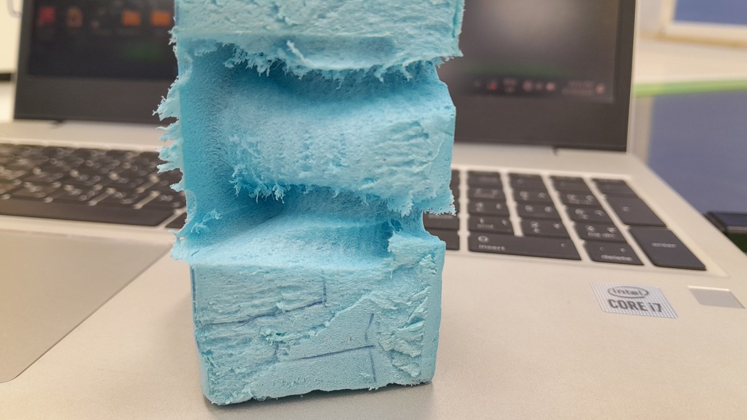
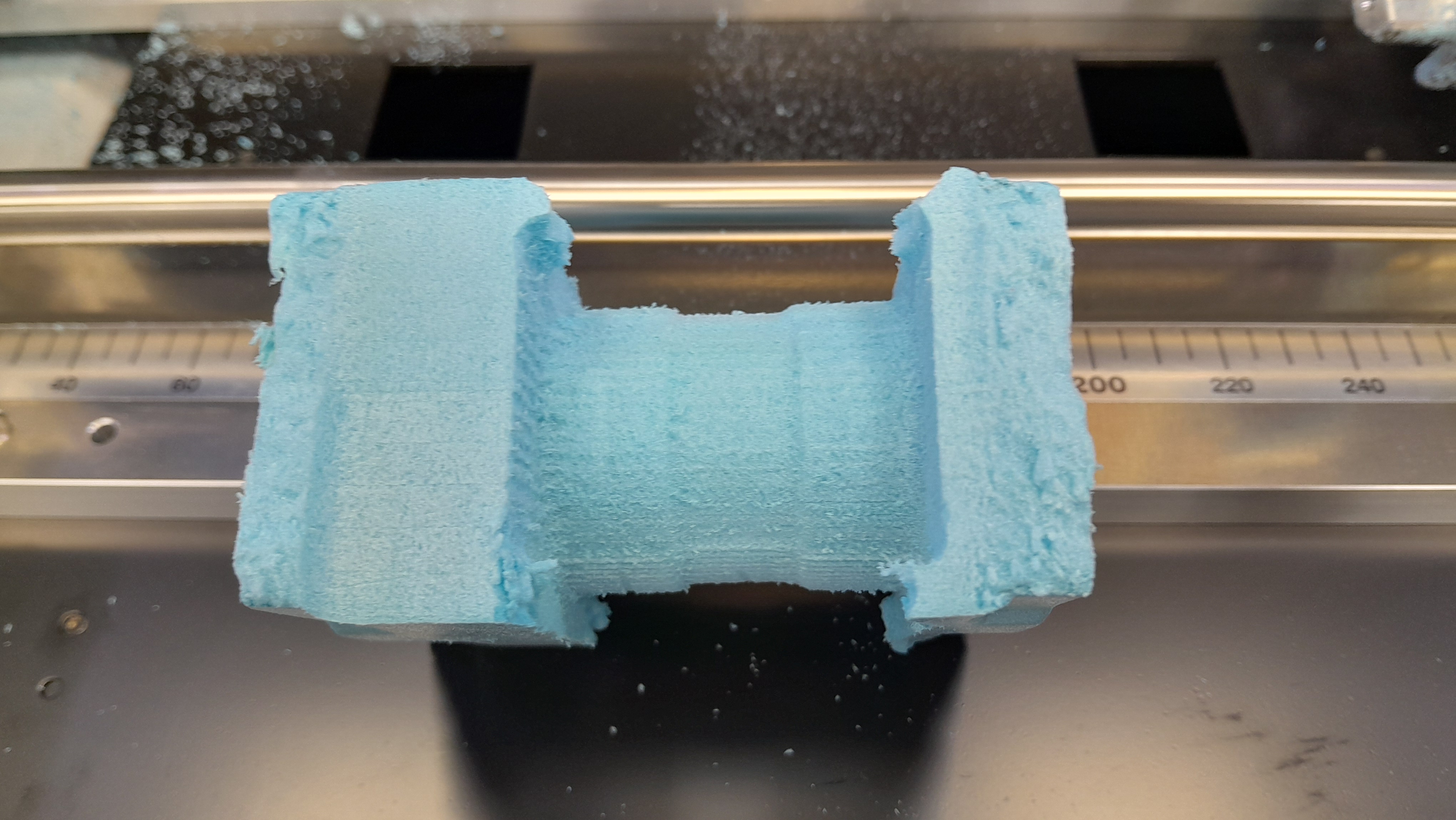
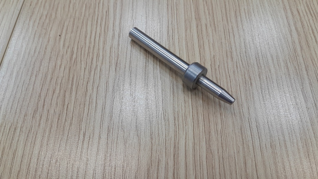
Final result HeroShot:
The fixed bed:

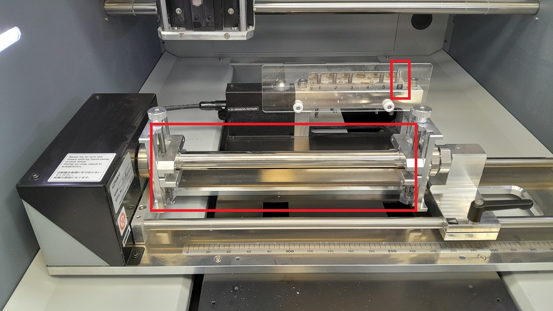
The rotary axis:
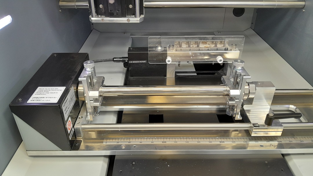
Setting up the machine:
I needed to uninstall the stationary table and install the rotary axis. so I unscrewed the table the placed the rotary axis like the manual said the there are some dints in the bed to indicate where the rotary axis should be. *** WHEN INSTALLING THE ROTARY AXIS AND CONNECTING IT TO THE MACHINE MAKE SURE THE MACHINE IS UNPLUGGED AND TURNED OFF BEFORE CONNECTING. ***
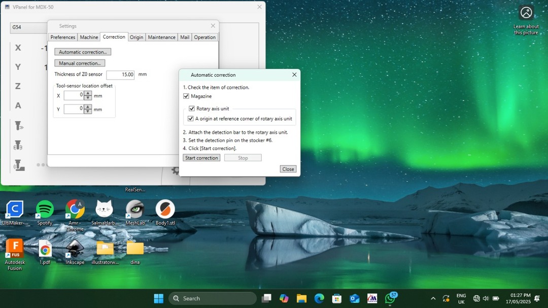
Auto correct the Y and A axes:
According to the manual of the machine this auto correction needed to be done if you just want to run the machine for the first time, you remove the rotatry axis and want to install it again or you need to rest the Y and A zeroes. So I followed the manual steps for that.
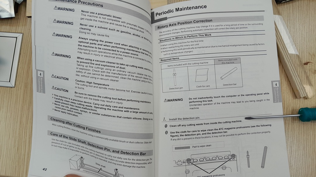
- First install the detector pin/tool in slot number 6 of the machine tool magazine.
- then install the detection bar in the A axis.
- Then I open V-panel (the software that comes with the machine) and go to the correction menu and then choose Automatic correction then Start corecttion.
After the auto correction I installed the workpiece and placed the endmills I will use the one I have available and I will be using is a 6mm ball nose endmill and a 3mm flat endmill.
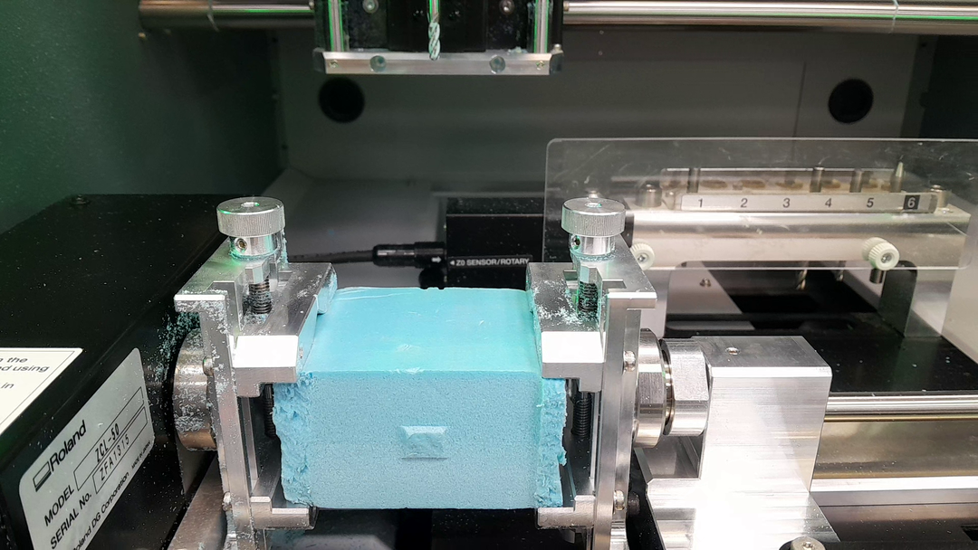
After I placed the workpice I made set the X, Y, and Z zeros for the work piece as when I get to what I did in fuion this is related.
Now that everything is ready let's go to the next step.
Getting the gcode and toolpathes
I struggled throughout this step but I will put the final result I reached and I may add what I did wrong and what caused it after.
I used Autodesk Fusion 360 to get generate the NC files. I learned through the journey that the MDX50 doesn't support continuous rotary motion and support indexed rotation so I
- I started with designing a simple shape I made a cylinder that has a grove on it.
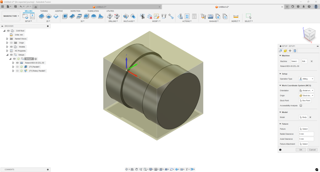
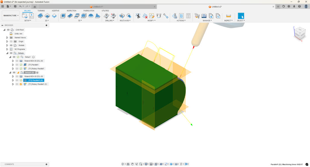
- Then I went to the manufacture workspace. and added a setup.
- After added the setup setting which involves the machine I use and the orientation of the workpiece. For my first orientation the Z axis should be upworks and the X axis should always stay in the direction it points to. What we need to rotate each time id the Z axis.
- After I finished with the setup I chose the 3D parallel toolpath to be done (you have to use a ball nose endmill for this operation.)
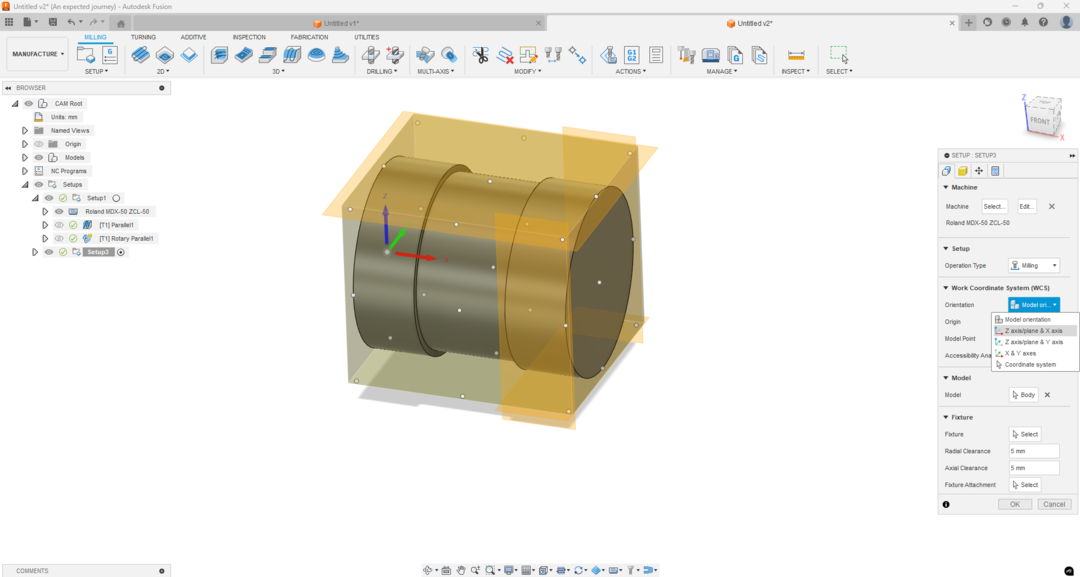
- After that I duplicated the setup and edited the orientation using the planes I made and the orientation (z axis and x axis option)
- And so on until we rotate the workpiece 360 degree.
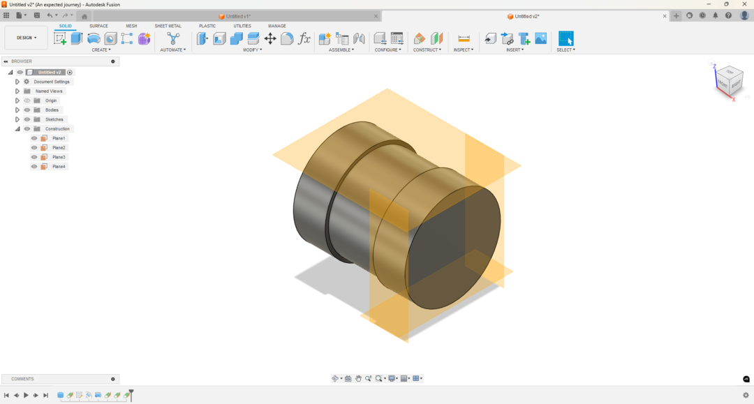
I added tangent construction planes to make it easier to orient the workpice.
.png)
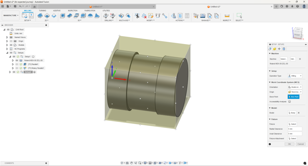
For the origin of the workpice I chose the backcenter point. (That is why I pointed the Z0, X0 and Y0 in the machine like I did.)
.png)
After that all you need to do is open the new setup and refresh the parallel to show you the new tool path.
.png)
.png)
.png)
.png)
Note: that if we generated all the toolpathes at once we will never get what we need so I added the paths to gether manually and updated the angle of the A axis manually by 90 degrees.
I generated each gcode out of each setup I made and then combine them in a single file adding the angle code:
I just right clicked on the setup the chose the NC program generate:
.png)
I then chose the machine post processor and then hit post:
.png)
I did these steps for all the setups and then added them all in one file separated with the angle code.
.png)
.png)
.png)
.png)
Now I have the gcode file.
I can go to the machine and start machining.
You can download my files from here:
Problems I faced:
The First one is that when I tried to mill the machine and the feed rate was so low and the spindle speed was low the machine stuck and gave an error that there us much current has been drawn.
To solve that I edited the spindle speed in the gcode file and override the feed to 130%.
Second problem I tried to dry run before cutting the material to see if there is something might go wrong. I the machine moved to the first point and the spindle kept spinning but it didn't move. That was because I made the Z0 too high.
That was easy to fix but it took my much time to realise that.
Third problem I didn't set the write origin in fusion and the machine so I got that instead of a sphere ^^.