3-Computer-Controlled Cutting
Assignments
Group Assignment:
- Identify your lasercutter’s focus, power, speed, rate, kerf, joint clearance and types.
- Document your work to the group work page.
- Also document what you learned to your individual documentation page.
Individual Assignment
- Design, lasercut, and document a parametric construction kit(Make sure to include the lasercutter kerf, which should be able to assembled in multiple different ways)
- Cut something on the vinyl cutter.(most probably a sticker:)
Learning Objectives
- Demonstrate and describe parametric 2D modelling processes.
- Identify and explain processes involved in using the laser cutter.
- Develop, evaluate and construct a parametric construction kit.
- Identify and explain processes involved in using the vinyl cutter.
Include in documentation
- A Link to your group assignment
- Process on how you made your parametric design
- Explain how you made your press-fit construction kit
- Make something with vinyl cutter
- Include design files
- Include hero shots of your project
Here’s the schedual for this week:

You can view my timetable here
Group Assignment
You can view our group assignment here


I got this image from the previous fabacademy students documentation.
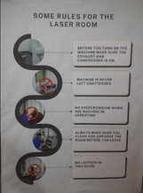
Safety Measures
There are many safty measures for this machine of course, but these are the main points I rounded up.
- Read the Manual
- Check the ventilation systems
- Inspect the Laser Cutter
- Attendence
- Ensure a Clean Work Area
Speed and Power settings are also important and highly variable…depending on the type and thickness of the material, and if you intend to cut or engrave. Generally, slower motion speed and higher power…are required to cut thicker, harder materials. Faster speed and lower power for thin, easy to cut (and easy to burn) materials. The ideal setting will need to be checked through trial and error for each material to be cut. This was tested in our group assignment.
Individual assignment
Vinyl cutter
This machine can be considered as a sticker cutter in general.(It cuts adhesive vinyl sheets into shapes for crafts, signs, and designs.) These are the parts of this machine

The blade used for the cutting process can also be changed depending on what you want to cut.

image_source I got the image above from aliexpress.
Safety measruments
Safty measurements aren’t really necessary in terms of the vinly cutter as its not that dangerous using this machine. Even so if you ever feel like following some safty measurments here they are.
-
Protective Equipment : Eye protectionl like glasses and gloves are the most important while working with this machine
-
Ensure the Cutter is Set Up Properly: Change all the settings according to your requirments and place the vinyl sheet carefuly.
-
Handling of Materials: Vinyl sheets edges may have sharp parts so be cautious when handling vinyl, as the edges can cause cuts or scrapes.
-
Electrical Safety: Proper Power Supply and powering off when not in use.
-
Machine Maintenance: Regular Cleaning of the machine to make sure there are no damages done.
-
Know how to opperate it: Familiarization with the Manual and learn the instructions needed to use it. If not, have someone who knows how to use the machine with you.
-
Fire Safety: Fire Extinguisher nearby in case of emergencies.
-
Do not overload: Make sure not to overload the machine with too many layers of vinyl, as this can cause jams or damage the cutter.
Assignment
First of all, heres some details on the machine
Model: Roland CAMM-1 GS-24

Software: Roland CutStudio and Adobe Illustrator

Cutting area: Maximum 584 (W) × 25000 (L) mm (22-1/1 (W) × 984-1/4 (L) in.)

Maximum material thickness: Around 0.1 inches (2.5 mm)

Cutting speed: 10 to 500 mm/s (all directions)

Usable tools: Roland CAMM-1 series blade

Settings:

Textile Vinyl: Speed: 15 cm/s / Force: 90gf

Copper Vinyl: Speed: 1 cm/s / Force: 40gf
The assignment was to try out the vinyl cutter and make something yourself. To use this machine, we have to:
Step-1: Download the file you want to cut. to do this, you can rightclick on the image, and select save as, and chose a name for your file.

This is the file I choose:

Step-2: Open cut studio.

Step-3: Adjust the size of the sticker material. Go to file, cutting settup, then select get from machine.(will directly send the size of the sticker material from the machine)

Step-4: Import the file you want to cut:

Step-5: Get the outline of the image.(right click on image to get this settings.)

From here. click on extract contour lines, then click ok.(drag the outline away from the real image, and delate the real image.)

This is the finished outline!

Step-6: Lastly, export the outline. Type ctrl + p to access the settings, and press ok at the bottom left corner.

This is the cutting in process:

Step-7: Weeding and Transfering your sticker!(be careful with this part of the process, espically if you have a lot of small parts/I ended up not doing this part to well)
Weeding: When you remove the unwanted parts of the sticker amterial to get your final outcome
Transfering: After your done weeding the material, transfer tape is used to transfer the sticker where you want to paste it.

And thats how you use this machine!
Parametric design kit
This weeks assignment had the task of designing a parametric kit, which is basicly a set of peices of different shapes that fit together without the need for any extra tools like screws, tape or glue. These sets of pieces should be able to piece together different structures.
Parametric is basicly a designing method where you can change certain parameters to chanf=ge the dimensions of a shapes model. This allows flexibility to the designing process.
Parametric Modeling usually uses the mathematical relationships in a way its all connected, so if you change the dimension for one part, the others will be affected as well ex- If the length of a rectangle is A, you could keep the height as A*2, so that when you change the dimensions of A, the height will change in the same manner.
Desigining
For this assignment, I did not start with a final product or predefined design. The goal was to experiment with laser cutter parameters rather than create a functional object. I designed a set of simple and random geometric shapes specifically to test how different speed and power settings affect cutting and engraving results.
Paramaetric designing
Kerf When laser cutting, the beam removes a small amount of material along the cut line. This removed width is called kerf. It varies depending on the laser settings, material, and thickness.
Slot Width: 4 mm - 2 * kerf The slots are meant to fit a 4 mm thick material, which is the thickness of the cardboard I used.
At first, I directly used the 4 mm value because I was working with only one material thickness throughout the assignment.It would have been better to define thickness as a parameter as well, so I could quickly switch materials without modifying every dimension. This is something I plan to improve in future designs.
The material used was cardbox, chosen because it is commonly used in the lab and clearly shows differences between engraving and cutting(It was our first time trying out parametric designs so we thought cardbox would be better so we could save the wood and acrilic for our future actual designs.). By using non-functional shapes, I was able to focus entirely on observing edge quality, burn marks, engraving depth, and whether the shapes were fully cut through at different settings.
To create the hexagon, I used the polygon tool in Fusion 360 and selected “Edge Polygon”, which lets you define the shape by setting the edge length instead of the circumscribed radius.
Some issues I faced while making this was because i didnt add the thickness as a sloth from the first, i couldent change the thickness of my hexagon, I had to remake the shape once with the thickness in the sloths as I got the thickness wrong t first.
Making the shapes
Step 1- Specify the Paremeters


Step 2- Make the sketch

type the name of the parameter you want to use into the dimension box


Step 3- Extrude the design(select create and then extrude.)

Step 4- Send stetch to laser printer.
Use the Project command (P on the keyboard) to generate a 2D outline of your 3d bodies. (click p on your keyboard to access these settings.)


Cutting and assembling
Step 1- Open inkscape and open the file. Change all the settings thats required then cut your design
In terms of vector cutting, turn off ‘Fill’, turn on ‘Stroke paint’, and under ‘Stroke Style’, set the unit of ‘width’ to ‘hairline’.then you arrange you design Enter ‘Ctrl + P’ to start printing.
For the material we were using, we were recomended to keep the power at 100% and the speed at around 30%. Keep int mind that power and speed settings depends on the type and thickness of the material you are cutting.

Step 2- Print your design. It needs to be cleaned time to time as well. Use a brush and a vacuum to remove the dust(sadly I didn’t have a picture of the clean frame taken )

This was my final outcome!


Design files.