- group assignment
- do your lab’s safety training
- test runout, alignment, fixturing, speeds, feeds, materials, and toolpaths for your machine
- individual assignment
- make (design+mill+assemble) something big (~meter-scale)
- extra credit: don’t use fasteners or glue
- extra credit: include curved surfaces
Group Assingment
The full group assigment can be found here. My part of the assignment can be found below.
File Preparation
Here I describe how to prepare the Aspire file for the CNC machine.
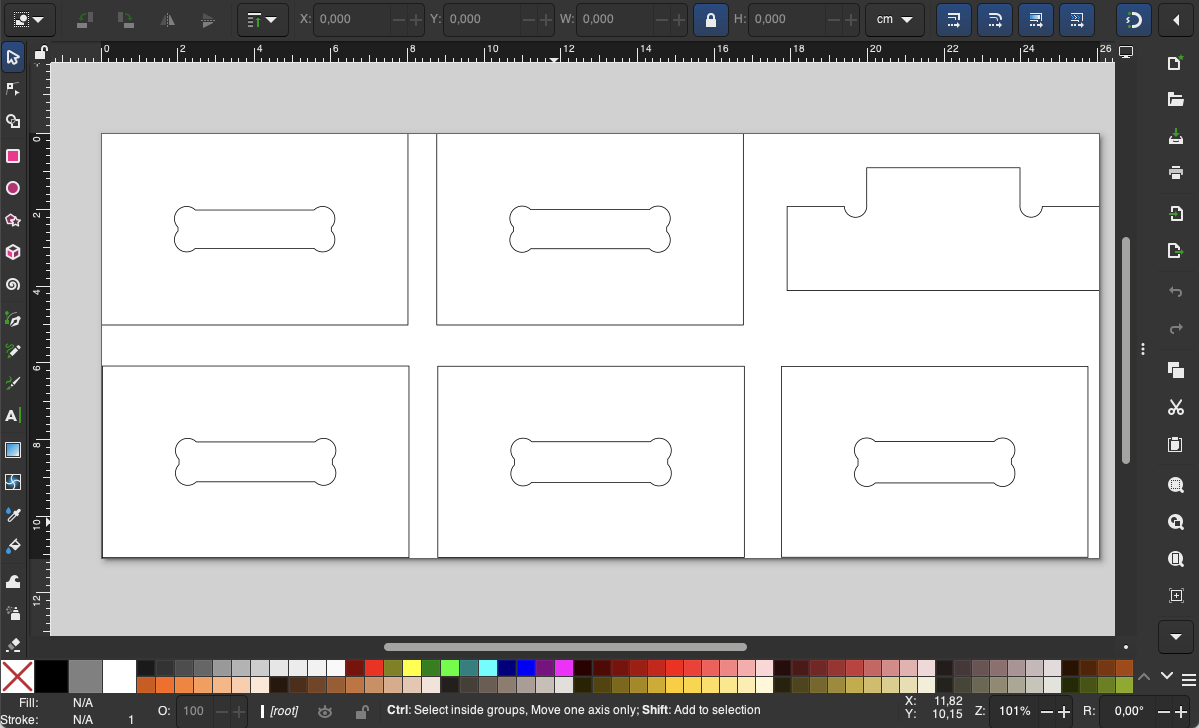
- We set up .SVG file or .DXF with the vectors to be cutted to be exported to Aspire.
Note: We want to arrange the files that we have exported with the sharper tool(Fusion) one by one in a svg file. In our lab’s workflow we import this as DXF into Aspire rather than an svg as the latter produces the following Aspire warning:

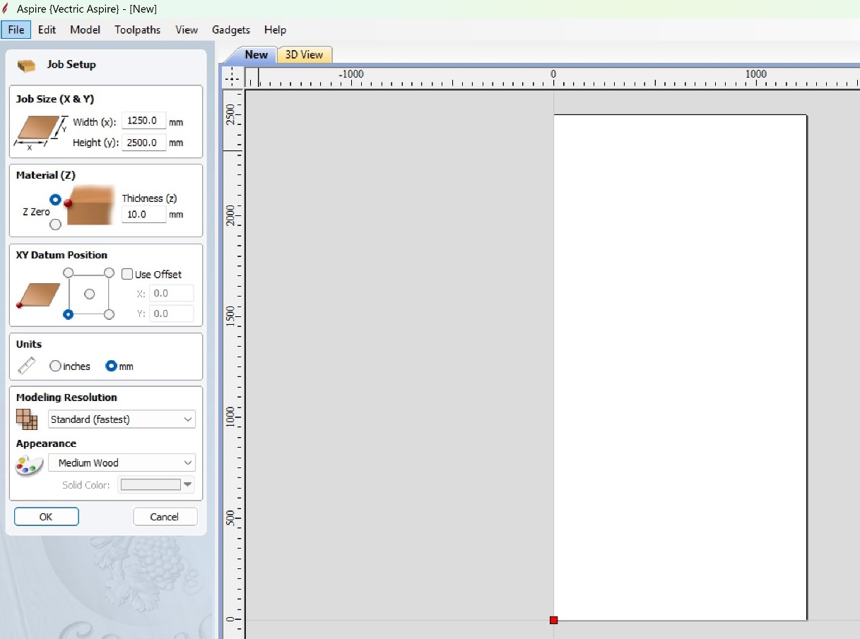
- Then in Aspire we set the dimensions of the board and the origin
point.
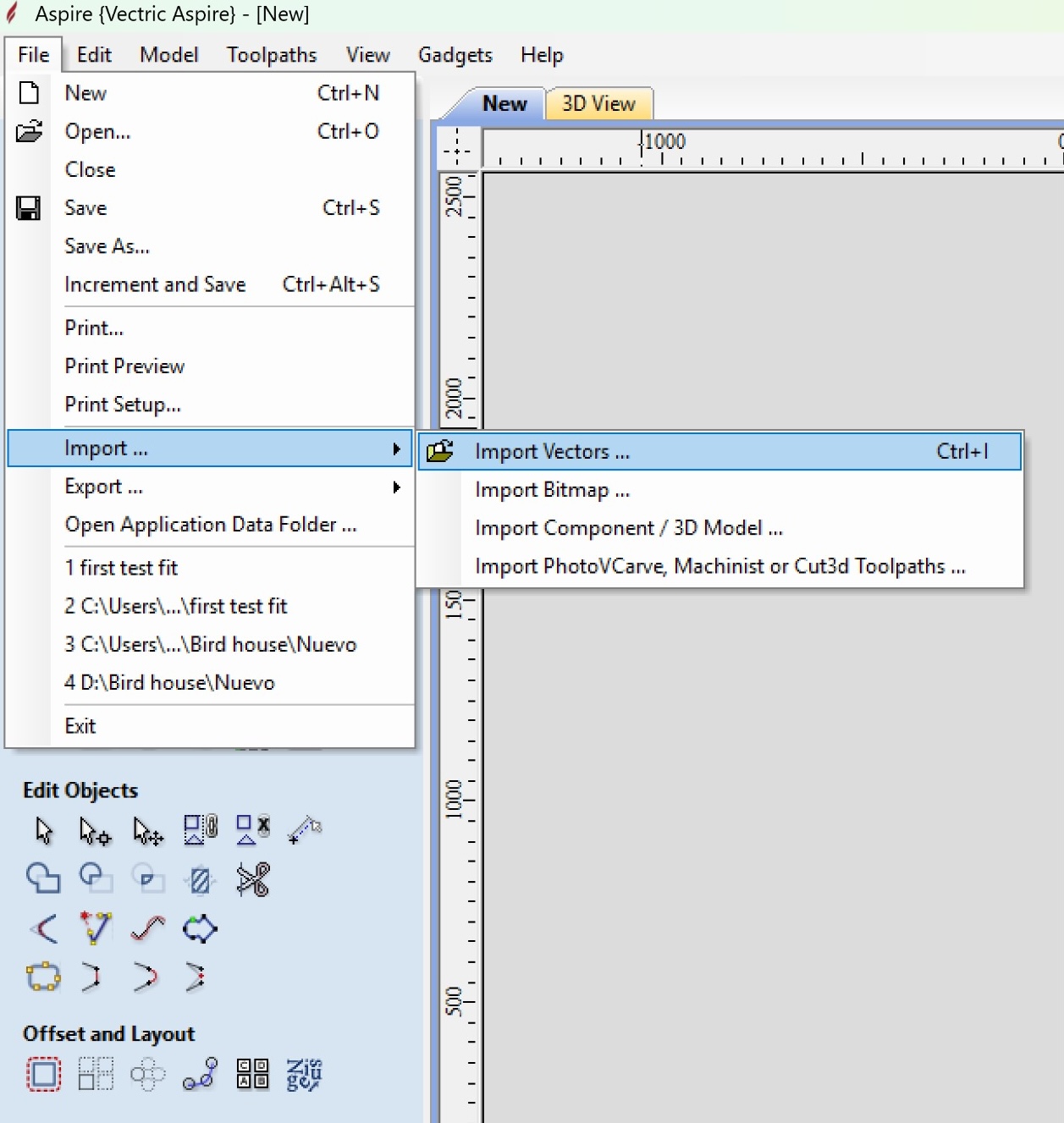
- We go to file and import a vector file with the tracing of the
object(see above).
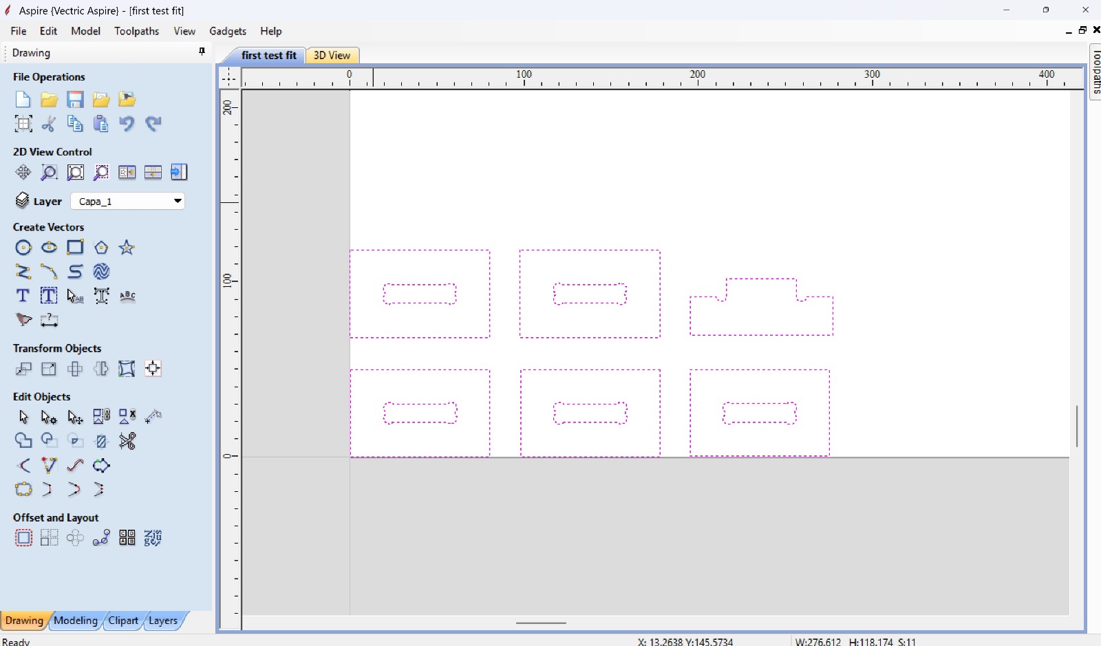
- We can observe the imported trajectories where the CNC machine will
cut.
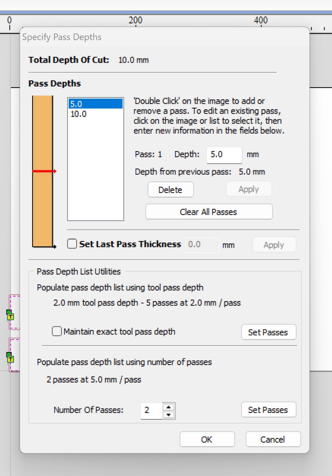
- We set the cut depth and the number of passes.
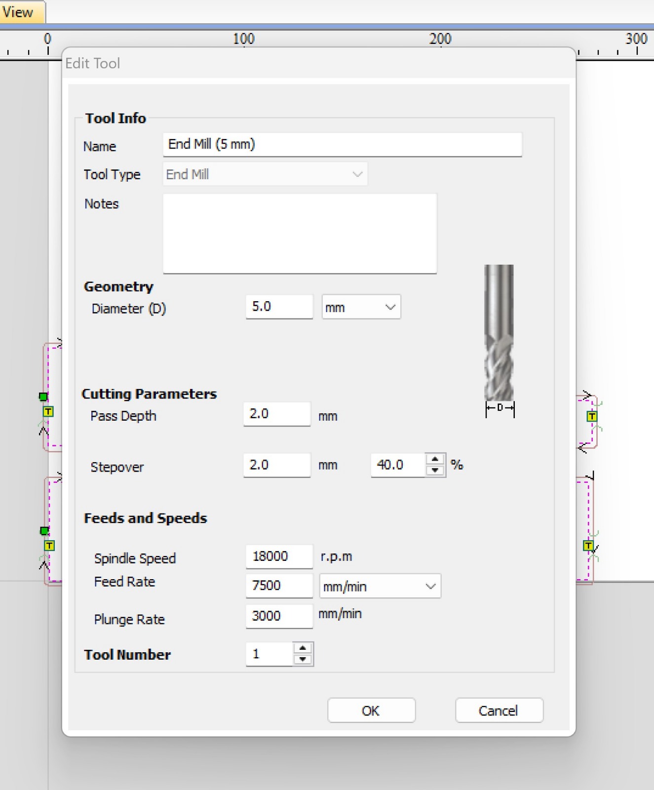
- Then we set the tool characteristics.
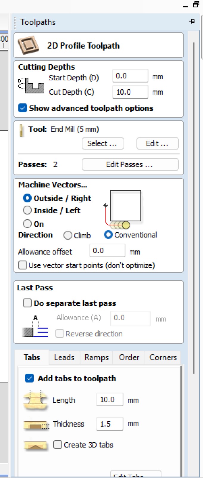
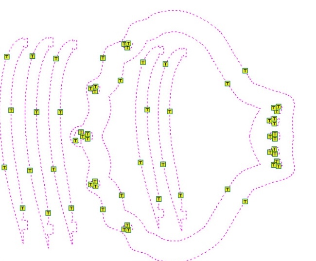
- Subsequently we set taps/bridges.
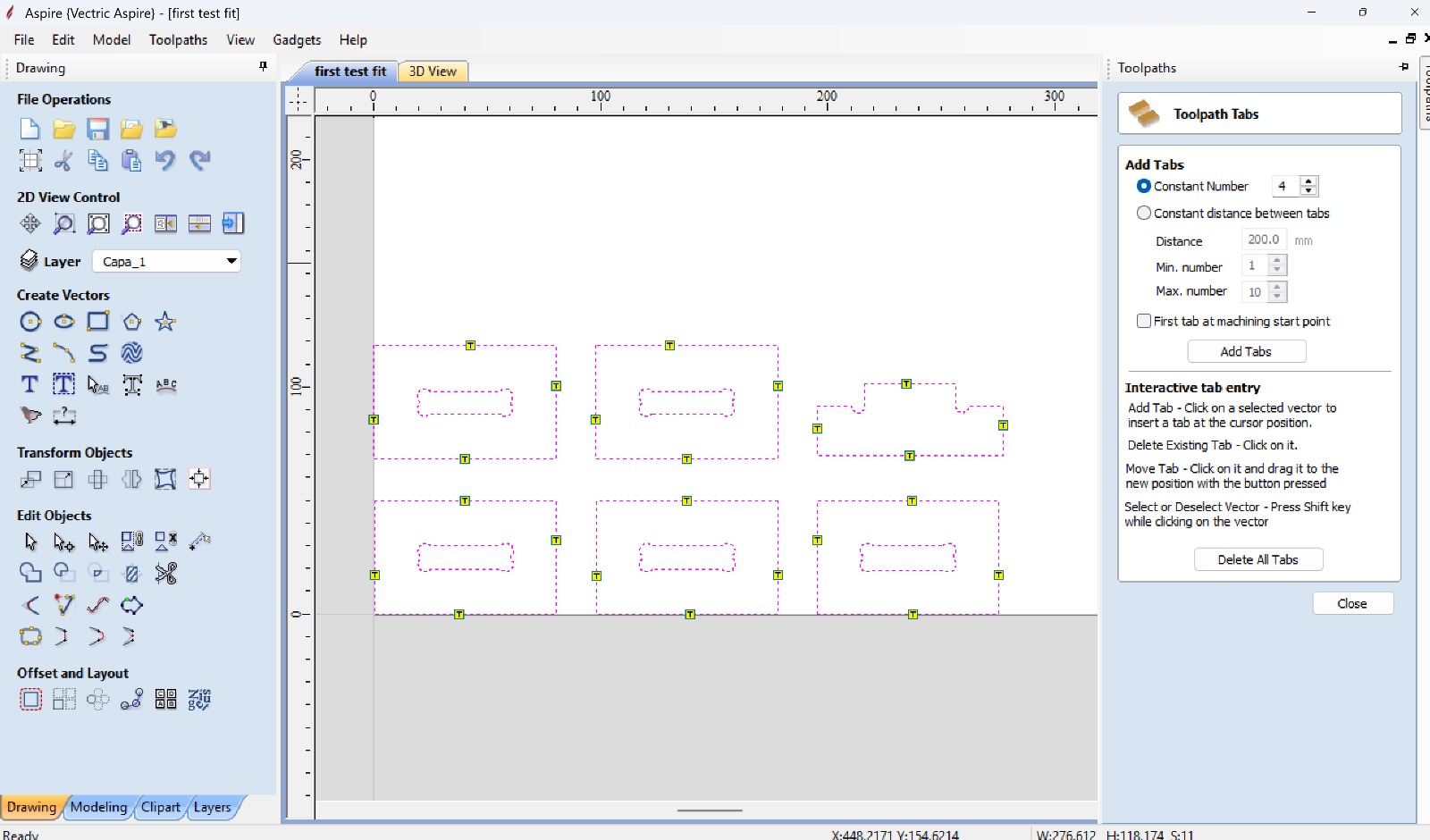
- We can edit the taps displayed produced by the program.
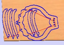
- And finally, the software allows to do a simulation of the cutting.
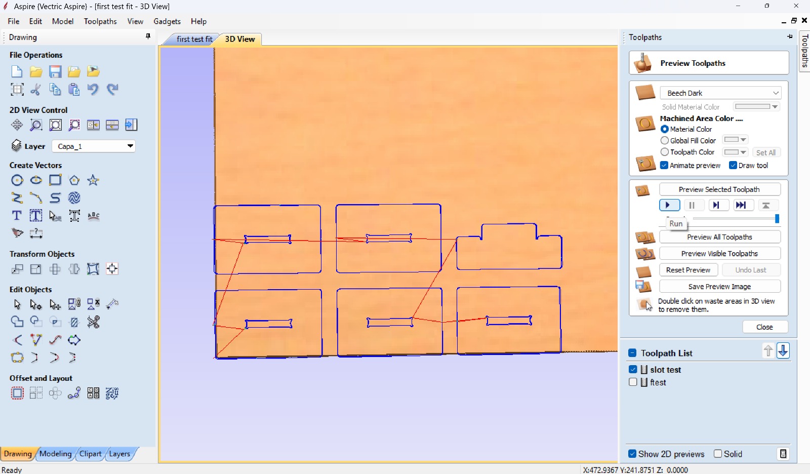
Pre-programation of spindle and feed speeds
Below you can find a image of the of the CNC control where you can see the different keys needed to operate the machine:
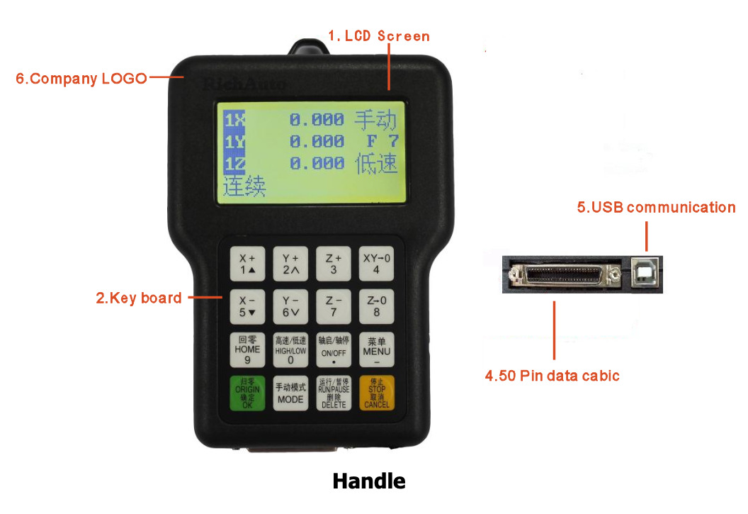
The control will allow us to set up preconfigured spindle and feeds speeds. Below you can find the sequence of commands to program these parameters as to have a set of options
- Press Menu → Auto Pro Setup → OK.
- Scroll to G-code setup→ OK
- Navigate to Read →press Run→ select ReadS→ press OK
- Press Menu→ Enter Machine Setup → OK
- Select Spindle Setup → OK
- Select Spindle State→ OK
- OK x2 to get to the speed set up menu
- Set the spindle speeds as needed:
- Level 8: 18,000 RPM
- Level 7: 17,000 RPM
- Level 6: 16,000 RPM
- Level 5: 15,000 RPM (for acrylic work)
- Level 4: 14,000 RPM
NOTE: Ensure that Aspire uses only these preset values (e.g., 18,000, 17,000, 16,000, etc.). Intermediate values like 16,500 will not be recognised by the controller.
- Configuring Feed Rate Recognition
- On the Rich Auto controller:
- Go to Menu → Auto Pro Setup
- Scroll down to Gcode setup → OK
- Choose F Read→ press Run
- Select Read F → press OK
- And stop/cancel to go back to main menu
- After completing these steps, the Rich Auto controller should correctly interpret both the
- spindle speed and feed rate as defined in Aspire.
Actions prior to cutting
Decide on the the type of cutting needed and change the bit for one that is appropriate. For this, the case that holds the collet will need to be loosened with a couple of wrenches. Depending on the width of the shaft of the bit a different collet could be needed.
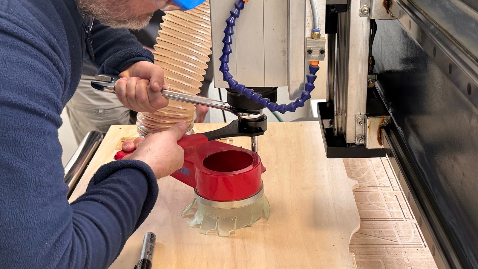
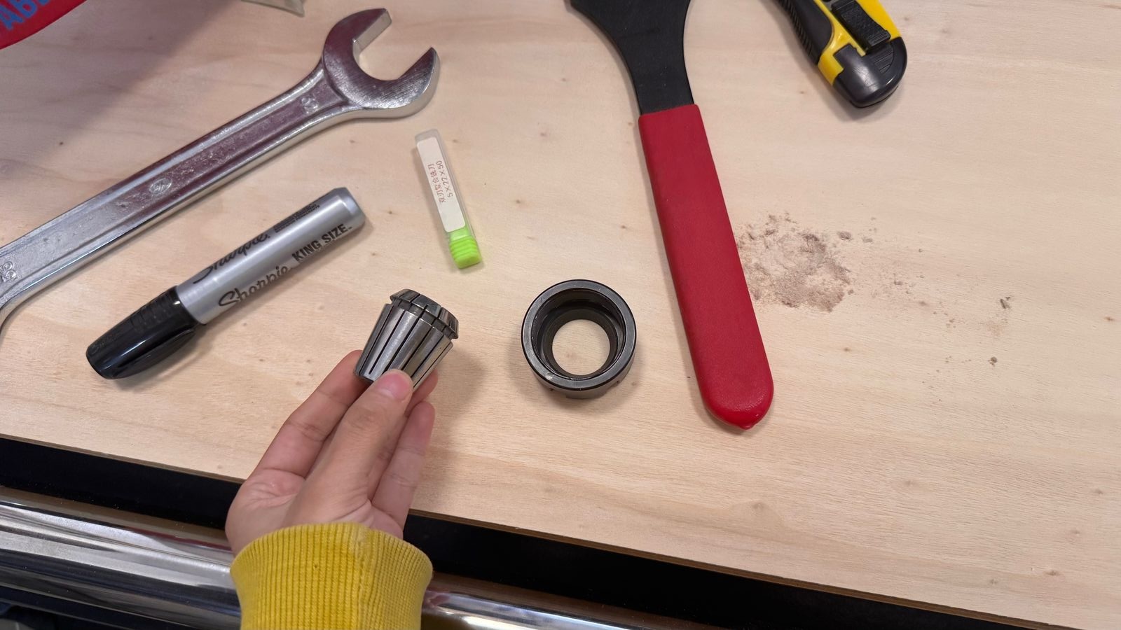
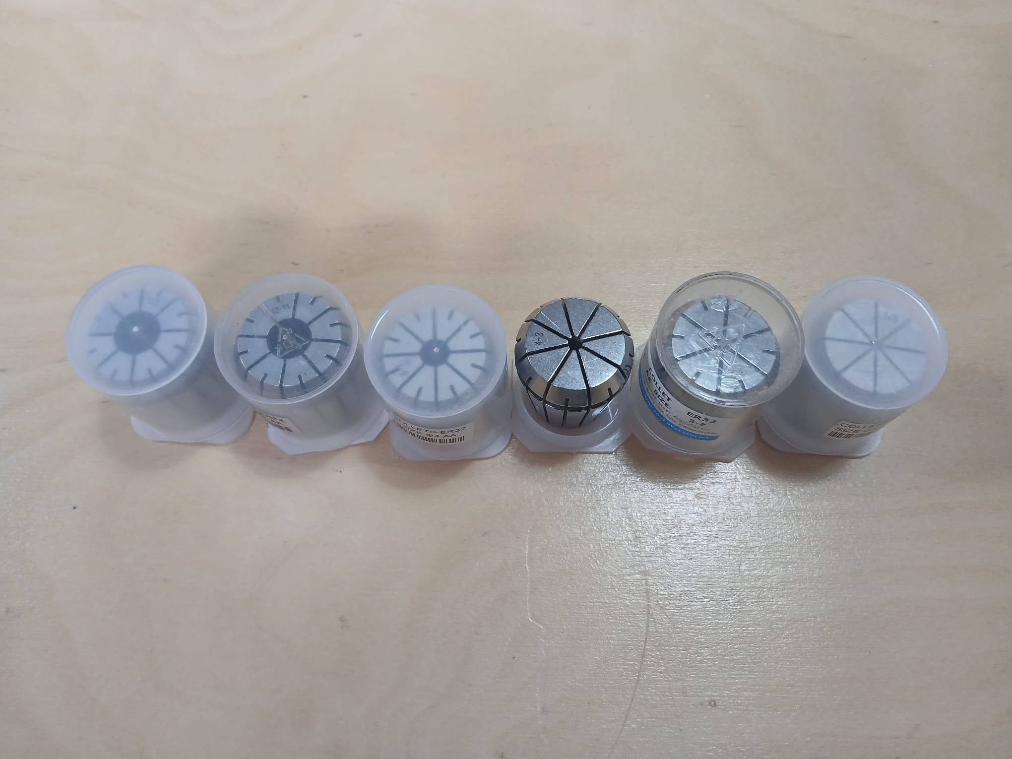
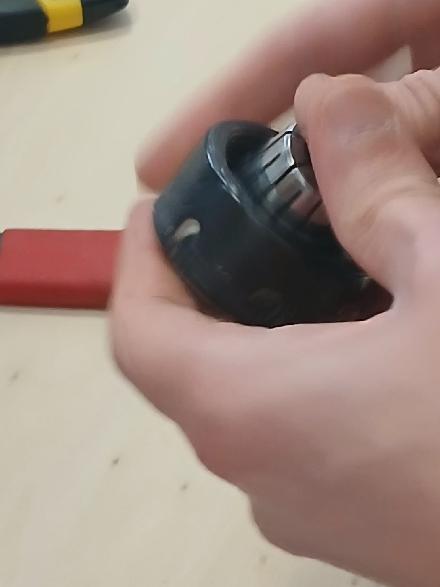
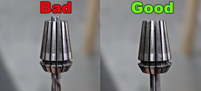
First snap the collet into the collet nut and then insert the bit. The shaft of the bit should not stick beyond the collet it should stay 3mm away from the end of the collet in case the bit is long otherwise it will not clamp well. Also, make sure that the flutes are not inside the collet.
Thereafter inspect the board to check that the board is even and flat. Otherwise correct for this with clamps or screws.
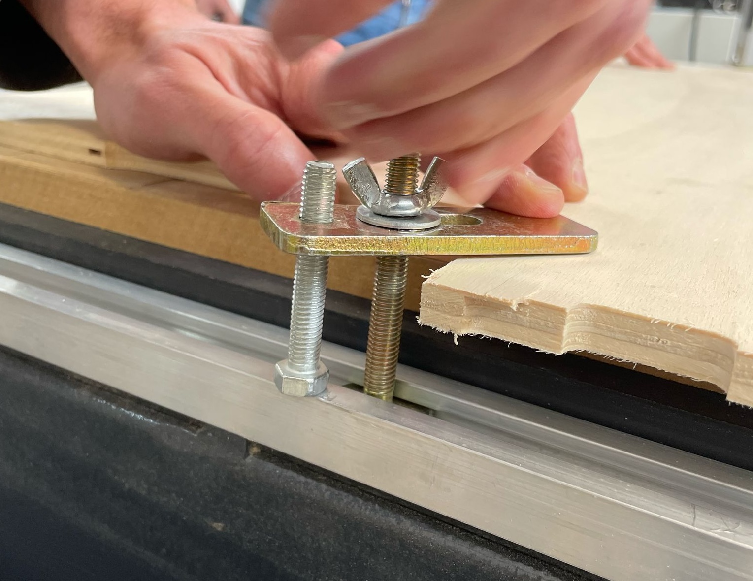
It is important to make sure that when setting the cutting area to take into account for this, in order to avoid that the milling over this metal pieces as it is very dangerous!
It is a good idea to test the table vacuum in order to see if the wood will move by pulling sideways.
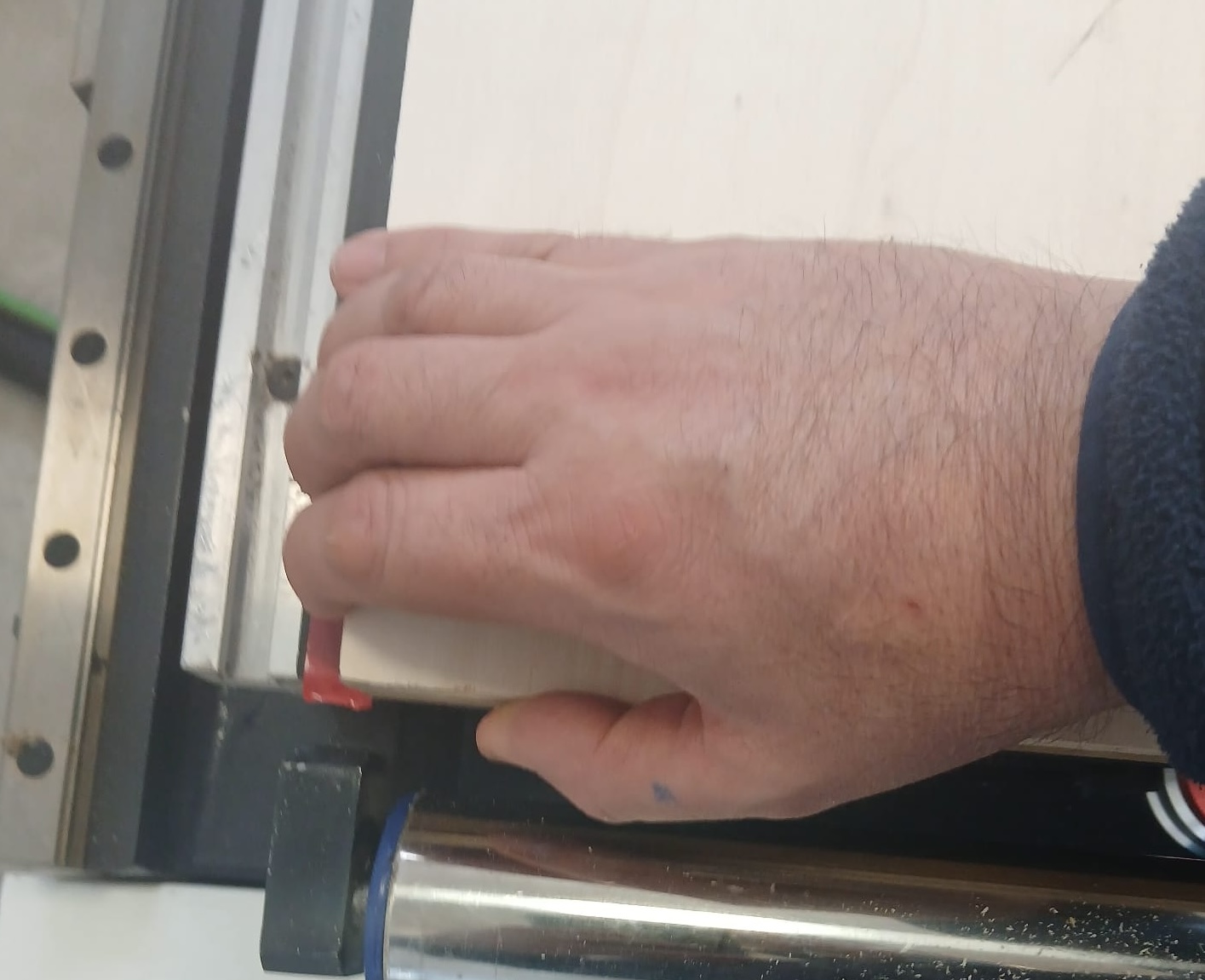
Use the controller xy + and - buttons to re position the CNC head to the start point or origin. Remember that x increases from left to right, z from bottom to top and y increases from the control station to the back of the room. In order to set up the z origin it is necessary to take small steps to touch the board lightly with the bit. In order to do this it is a good idea to activate the table vacuum as this will change the z position of the board.
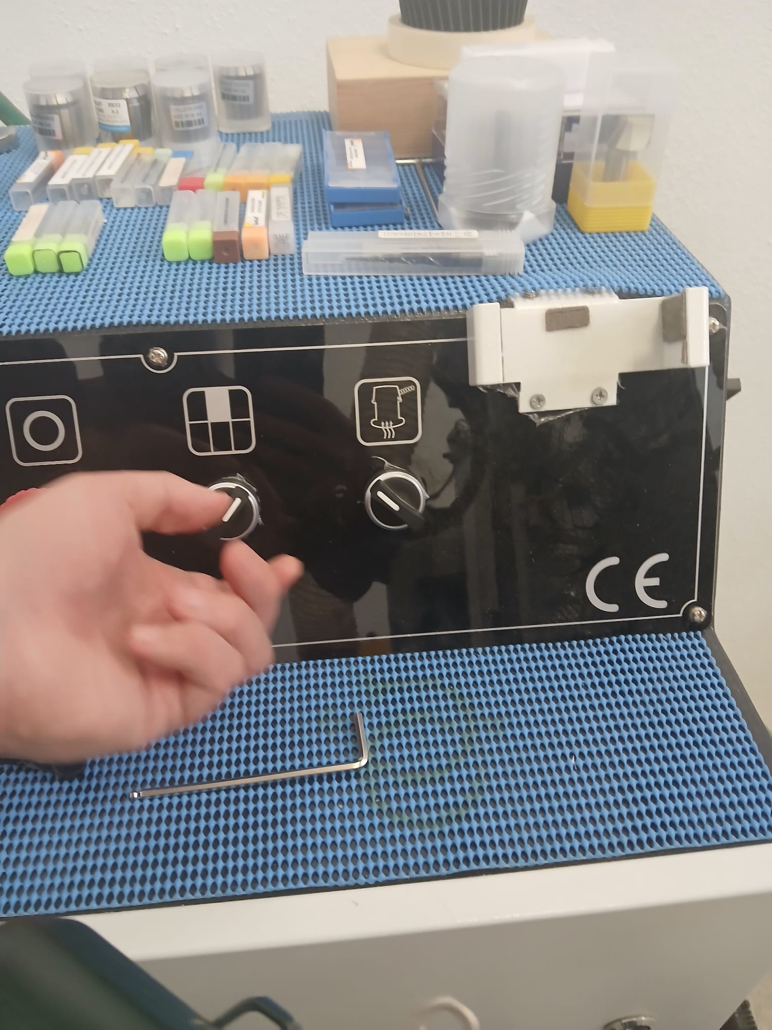
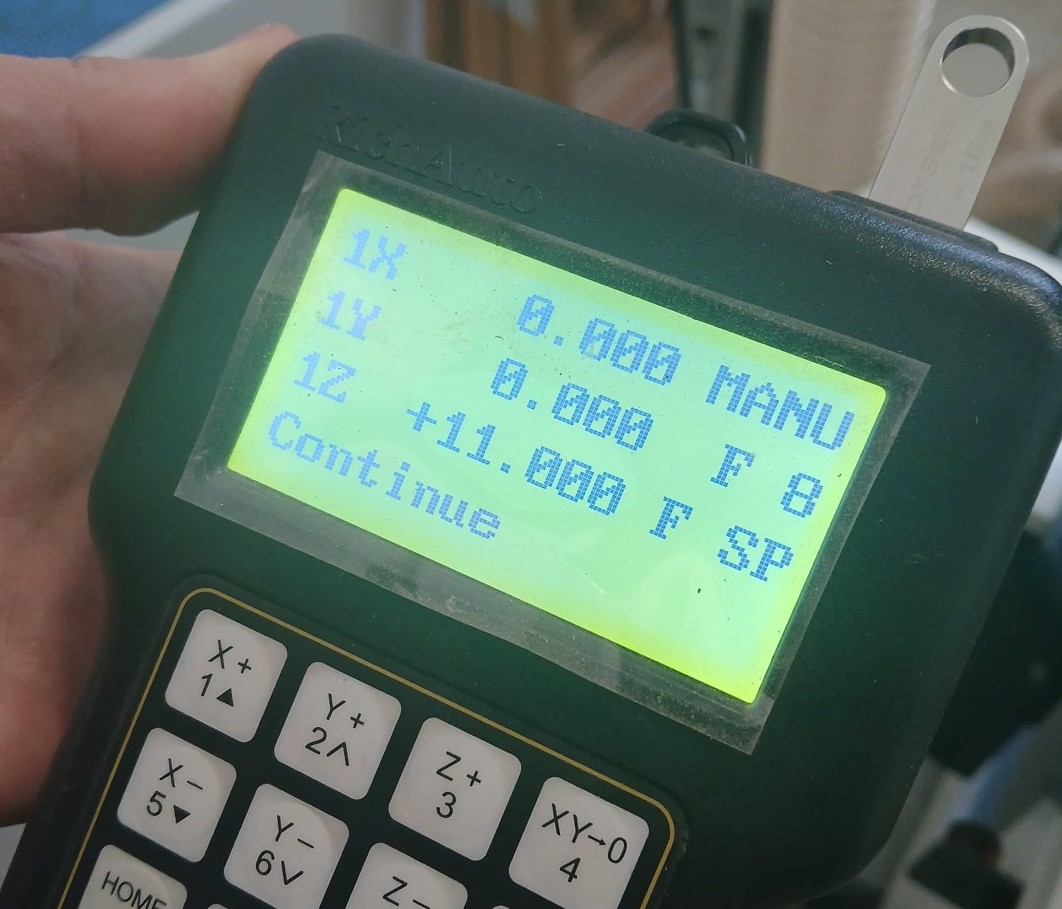
Cutting
- Connect the usb drive to the controller.
- Set up origin point: Then press XY->0 and Z->0.
- Thereafter, select the Run/Pause key to call the file menu and select UDisk using the x+ and x- keys + OK.
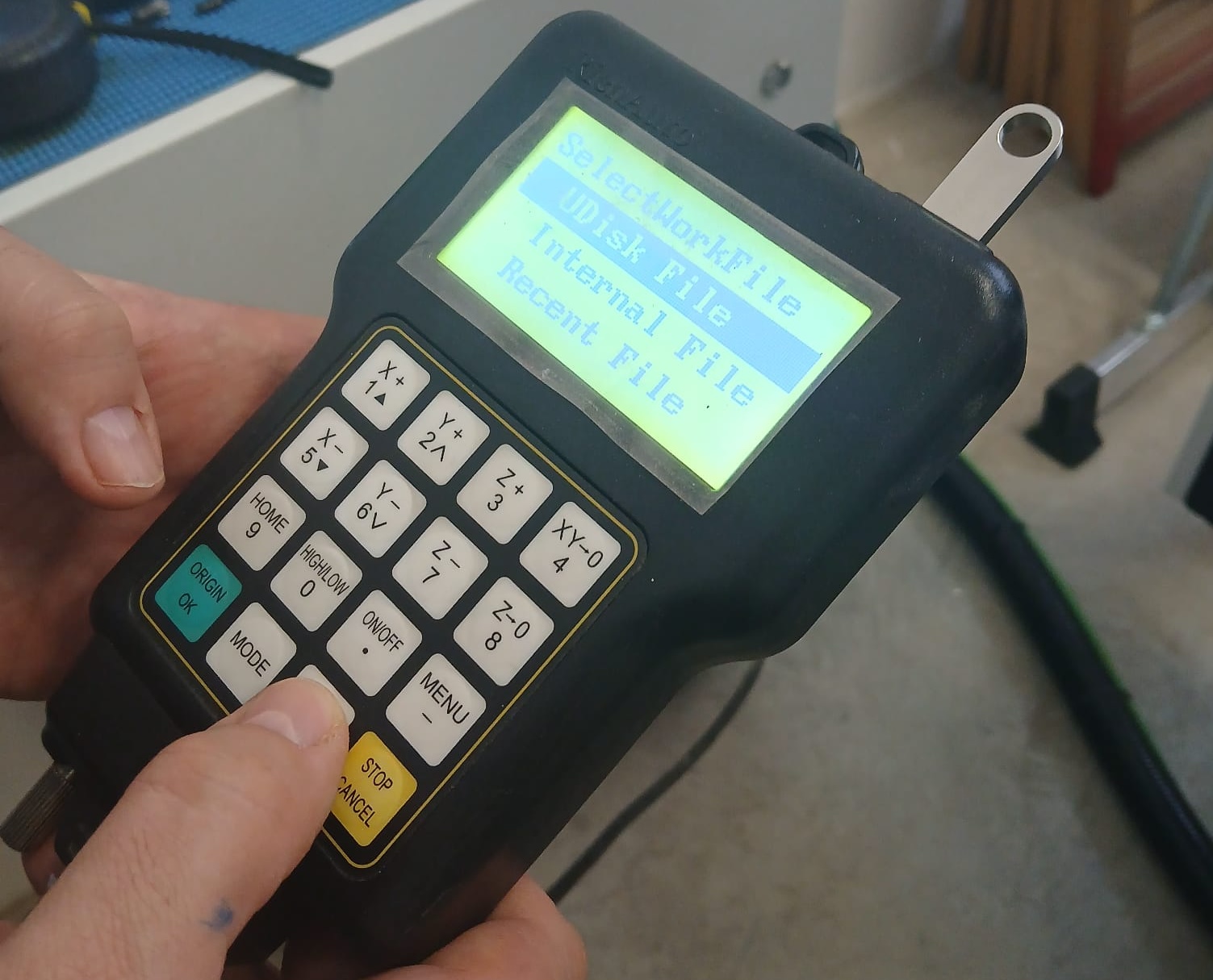
- After, you can select the Aspire file you created using the X+ and X- keys + OK
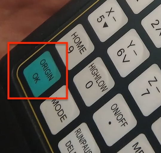
Note: The controller will use the parameters specified in the G-code as long as their values have been preset in the controller previously.
- Prior to sending the job if you haven’t already turn on the table vacuum sections that you need and the extractor.
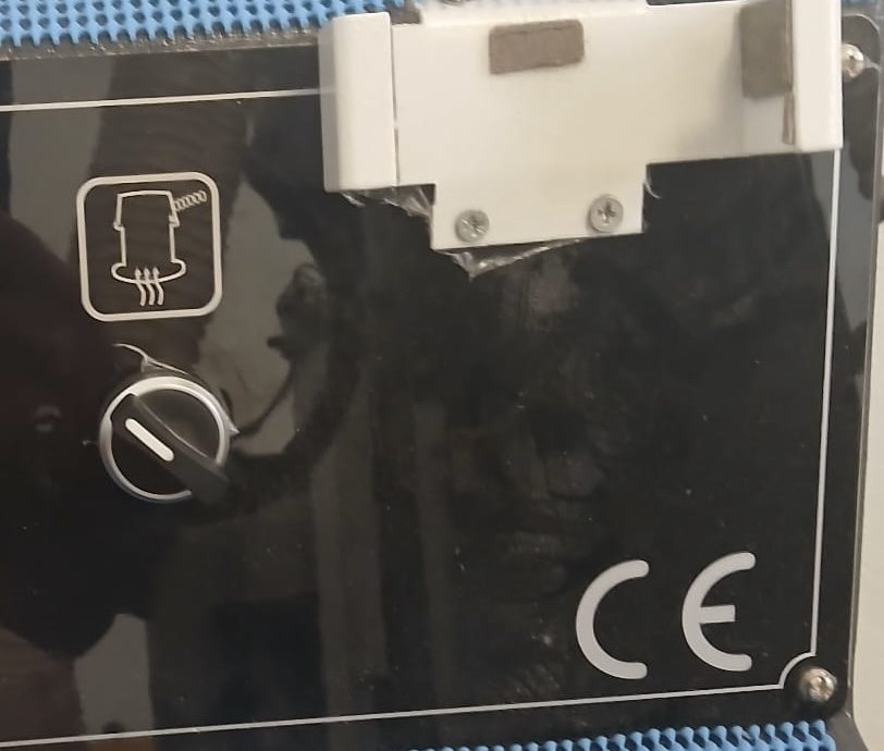
You may want to do a test run i.e. without cutting i.e. to see the trace. Make sure the you lift the CNC head in Z position to avoid cutting.
Send the job and stand in next to the control center always with a finger positioned in the stop key.
Tests
Press Fit Test
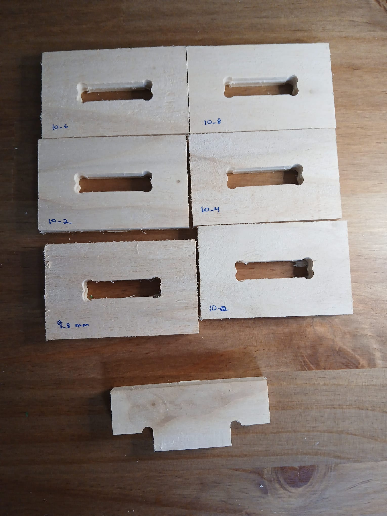
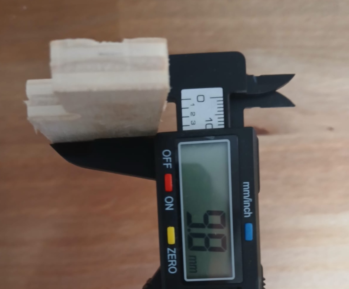
We created some cuts files for different path widths in order to evaluate fit of two pieces. Given that the regular dimensions of the board were 10mm we set up a range of slit widths from 10-10.8 with a step separation of 0.2 mm. We found that the 10mm cut provided a good fit but still could use some width reduction for better grip. We realized that the finger piece was actually 9.8mm in width. Then we cut an additional slit piece with 9.8 mm and this provided a good fit with good grip but was not excessively tight allowing still to separate them. Possible a 9.7mm slit would be great if we look for a permanent lock.
Note:the specified width dimension of the beech board is 10 mm. The width of the part of the board we use for the above had a deviation of -0.2mm (2%). There could be deviations from board to board depending on the production process.
 .
.
 .
.
Dog Bones Test
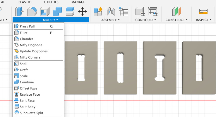
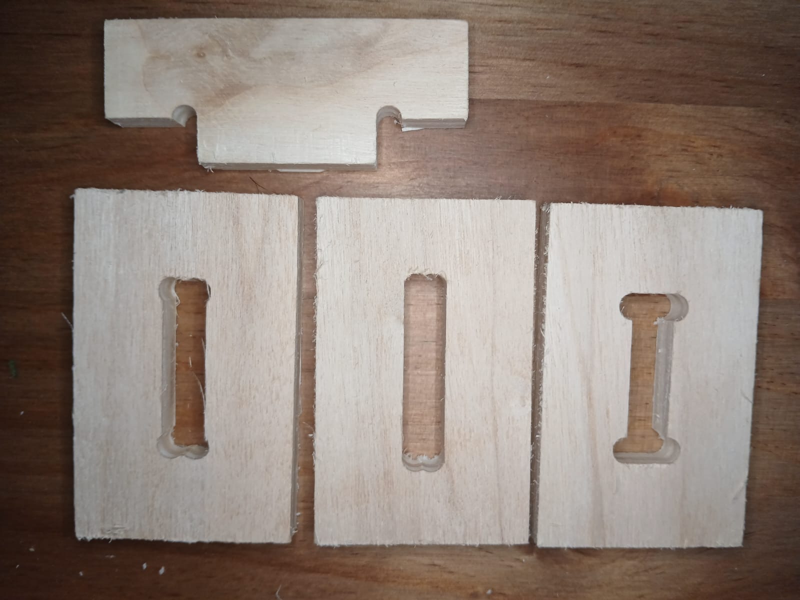
We wanted to see if different dogbones shapes had an impact on the fit so we tested 3 different dogbone shapes with slit widths of 9.8mm. We were not able to identify any differences in fit. We used the Nifty Dogbone extension for Fusion 360 that can be found:
https://apps.autodesk.com/FUSION/en/Detail/Index?id=3534533763590670806&appLang=en&os=Win64
 .
.
 .
.
Individual Assigment
Some general mill bit information
There is some information from global tools today that show how the different types of bit work specifically down cut upcut and compression bits.
Sumarized from:
Down-cut bit
Orientation: from the surface down.
Good for: for jobs where a clean surface is
needed.
Evacuation: force down and compacted.
Notes: not ideally in a deeper profile as chips are
force down as chip evacuation is limited. 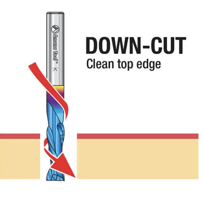
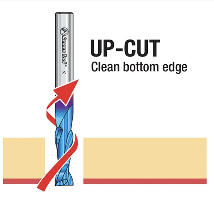
Up-cut bit
Orientation: From the bottom up.
Good: for having a clean bottom good chip
evacuation.
Evacuation: forces chips up.
Might not be the best for: potentially chip out on the
top surface of the material and may result in frayed edges.
Notes: efficient at chip removal.
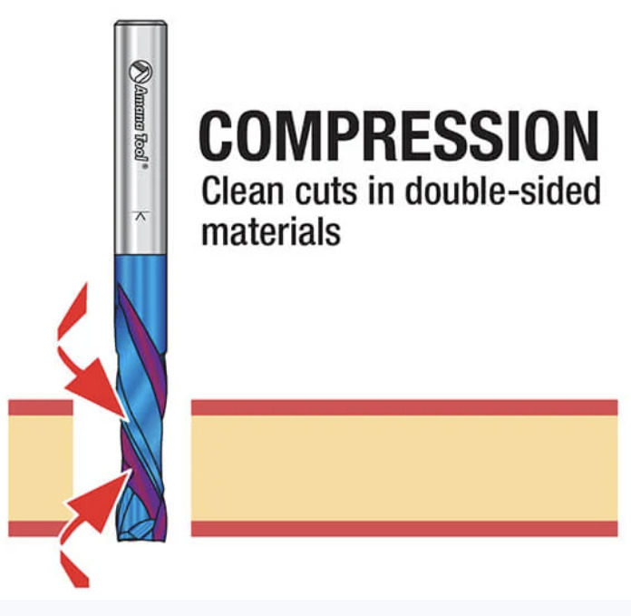
Compresion bit
Orientation: contains both both upcut and down cut
flutes. Good: for combining both mechanisms into one
which allows time reduction.
Might not be good: for a shallow process that requires
a polish top surface.
Notes : Must ensure that the first pass is below the
uncut part. The down cut part must be cutting at the surface to ensure a
clean top and bottom.
Build a Scallop (..lamp)
This week the goal was to design something big. For this I decided I wanted to design a Shell. I had big plans to use the sculpt functions in Fusion for it. At the end I did not have time or the skill level and ended up designing a much more simple version which you can find below.
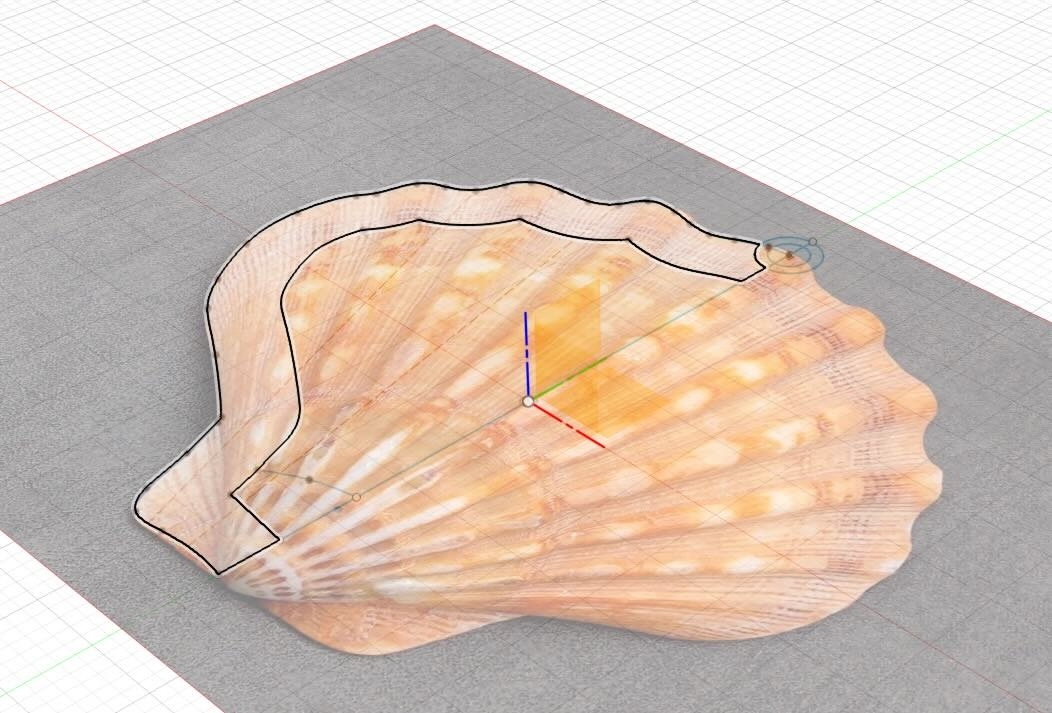
I fusion I use the canvas function for tracing the outline of a scallop.
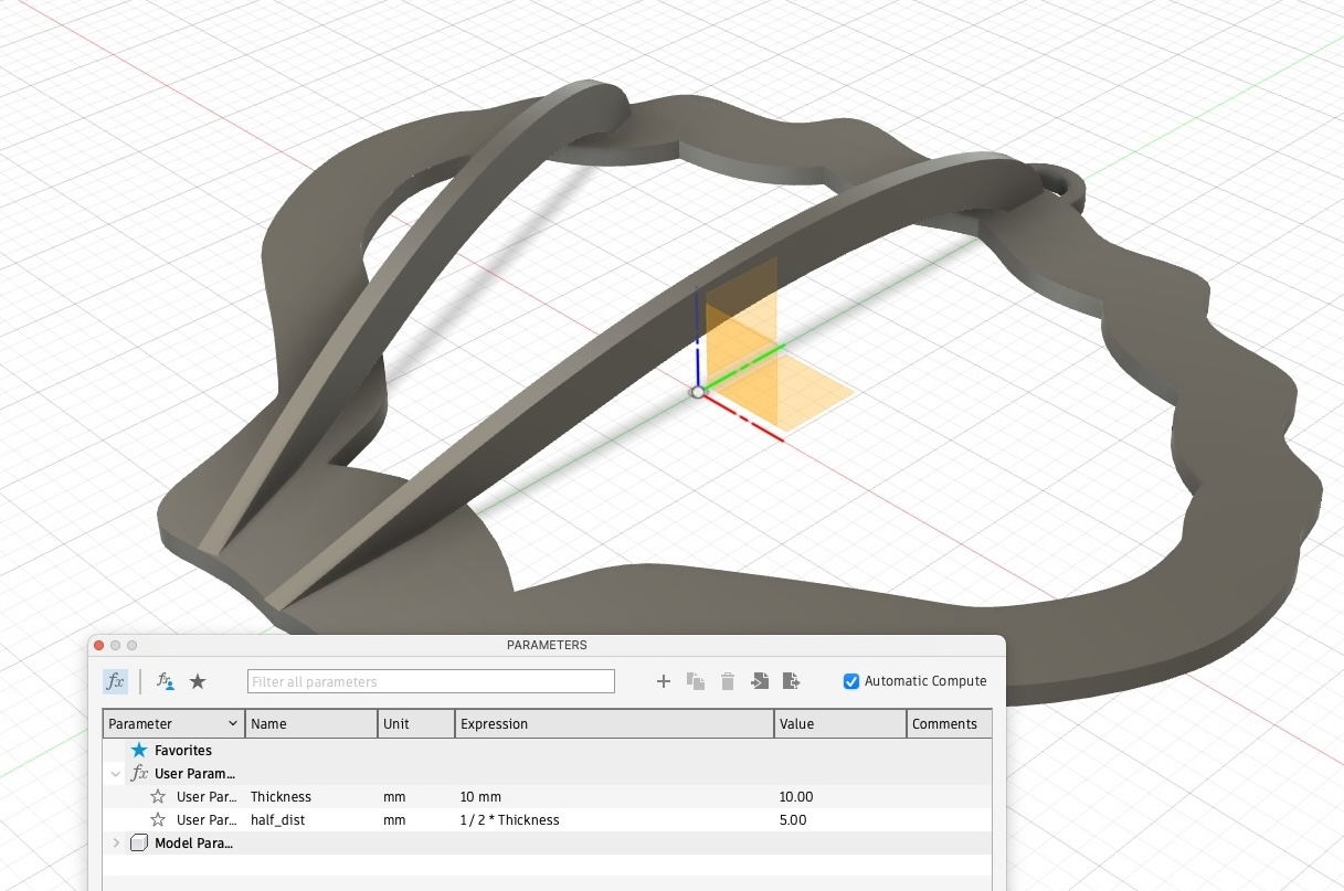
Note: that the board thickness is 10mm and as per our test above the same thickness for the slots should work well. I think it could be beneficial to roughly inspect the board thickness for deviations prior to cutting and to adjust the parameter accordingly.
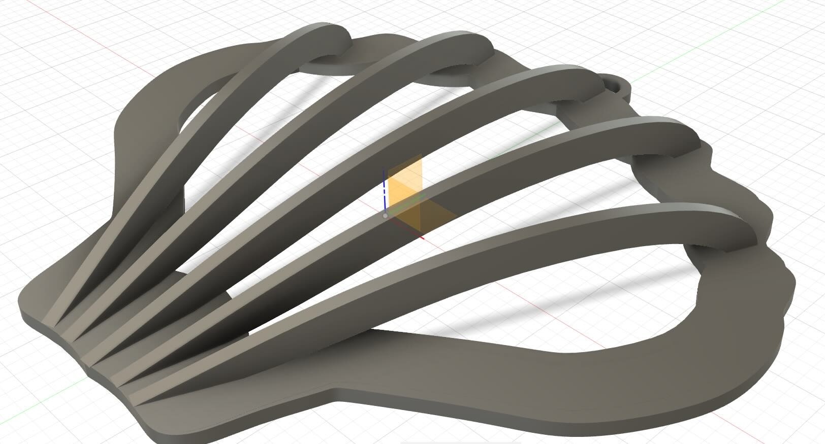
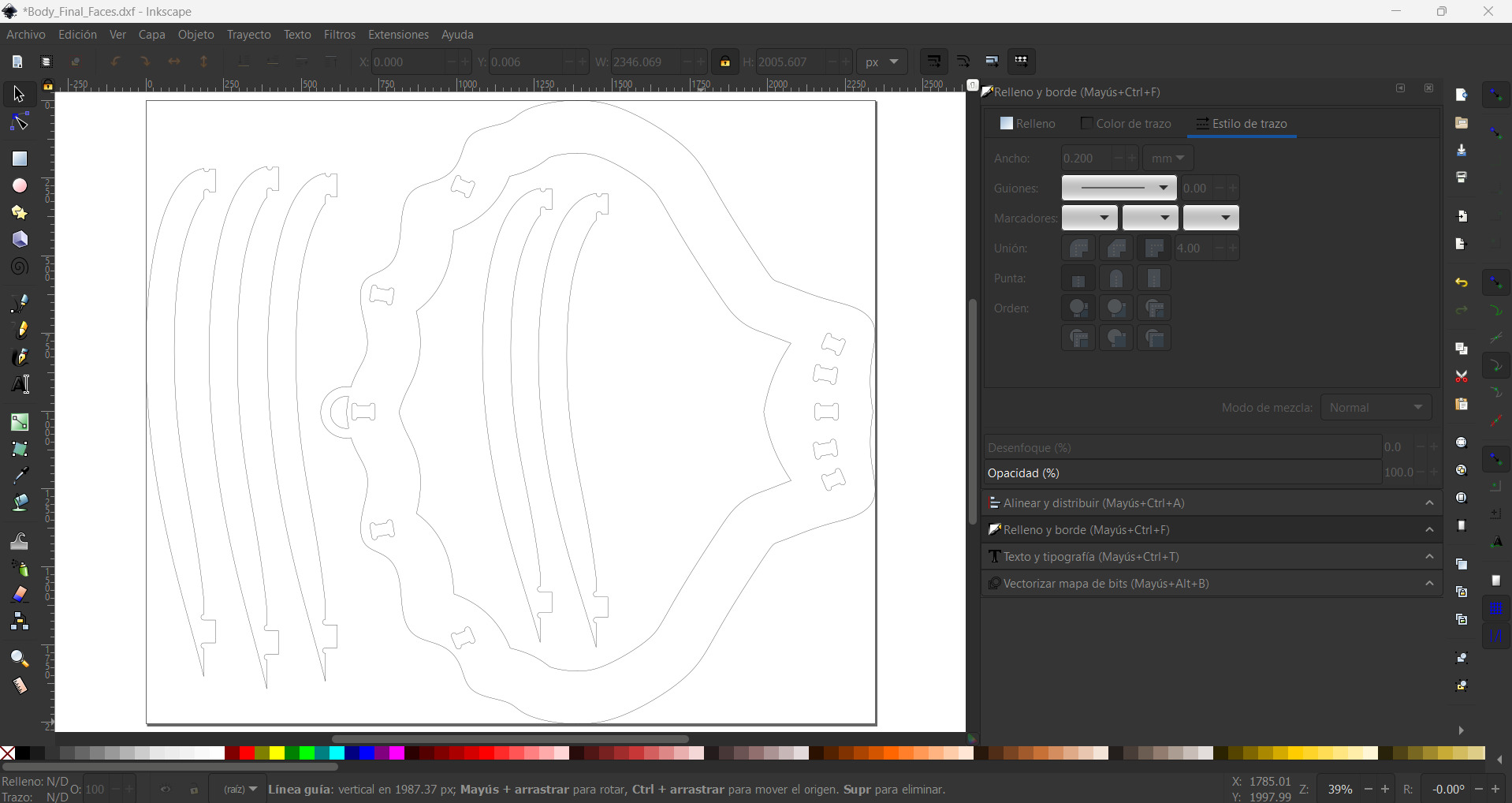
Then we export the different bodies with the shaper tool into an svg file.

And thereafter we use the individual svg files to built a combine Inskape to be imported by Aspire for processing (please see group assignment above.)
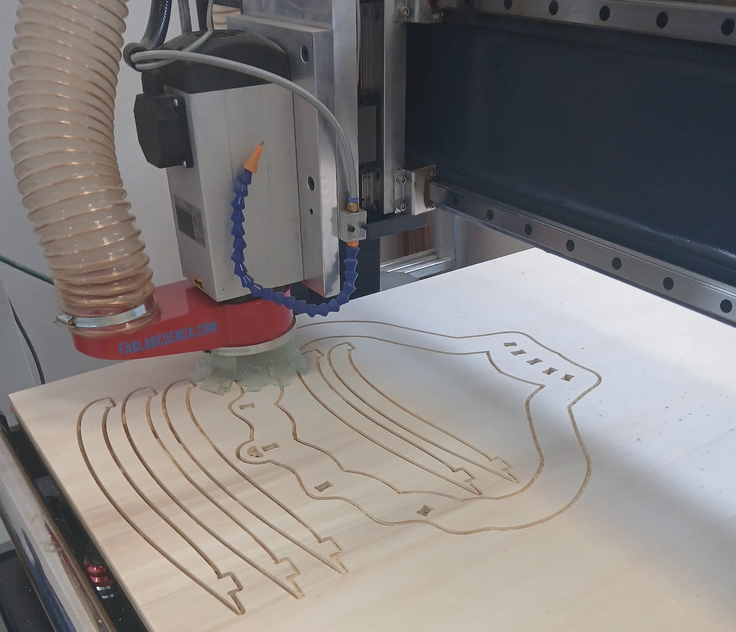
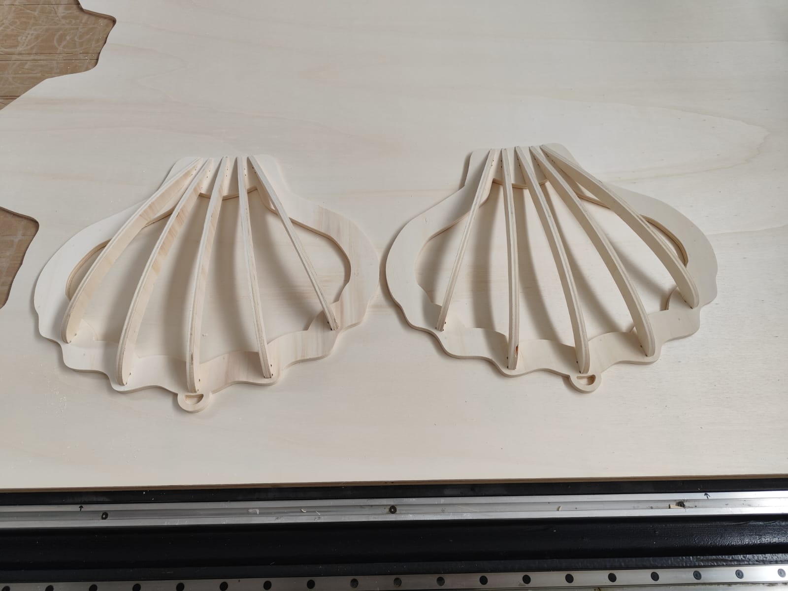
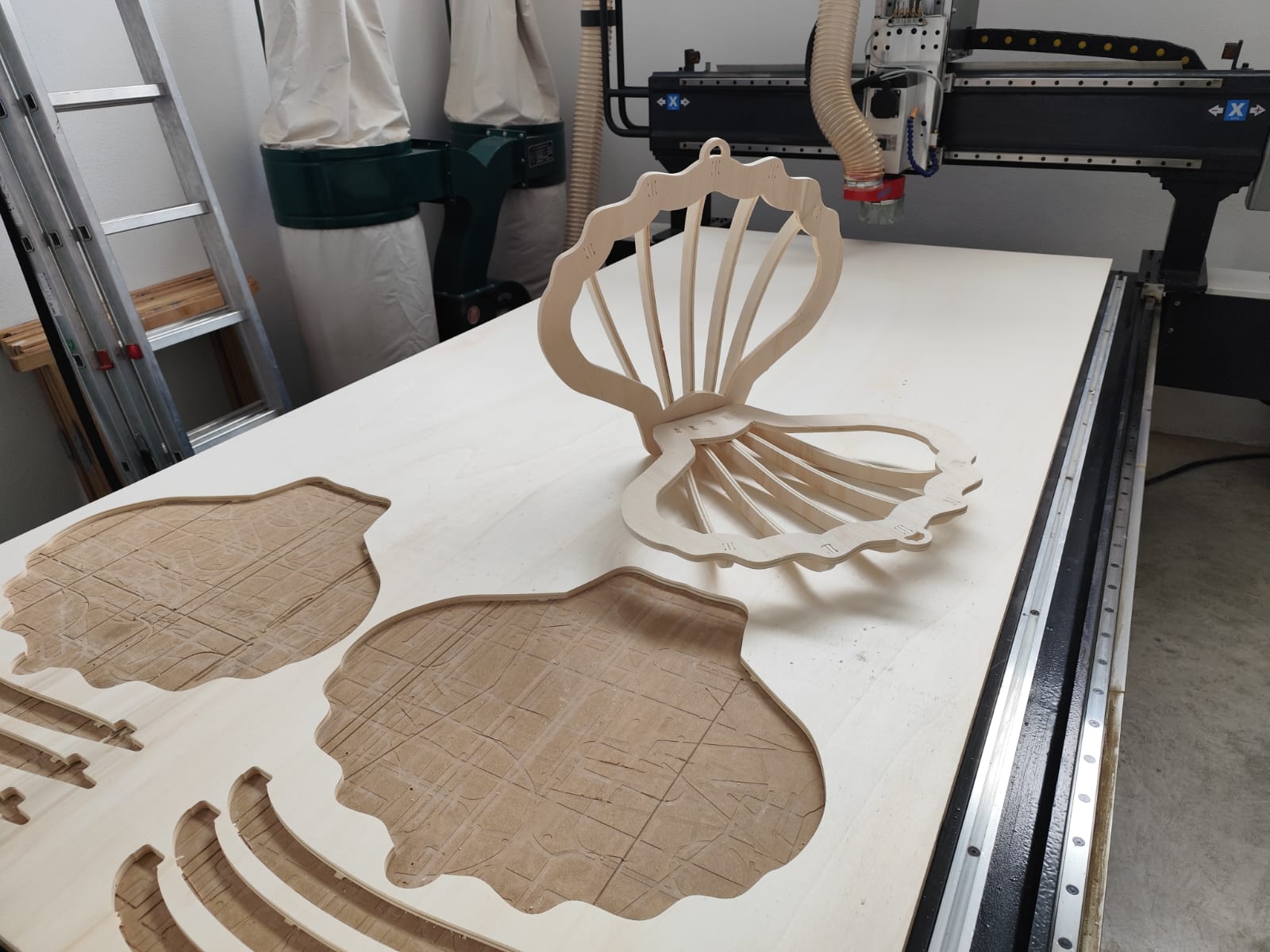
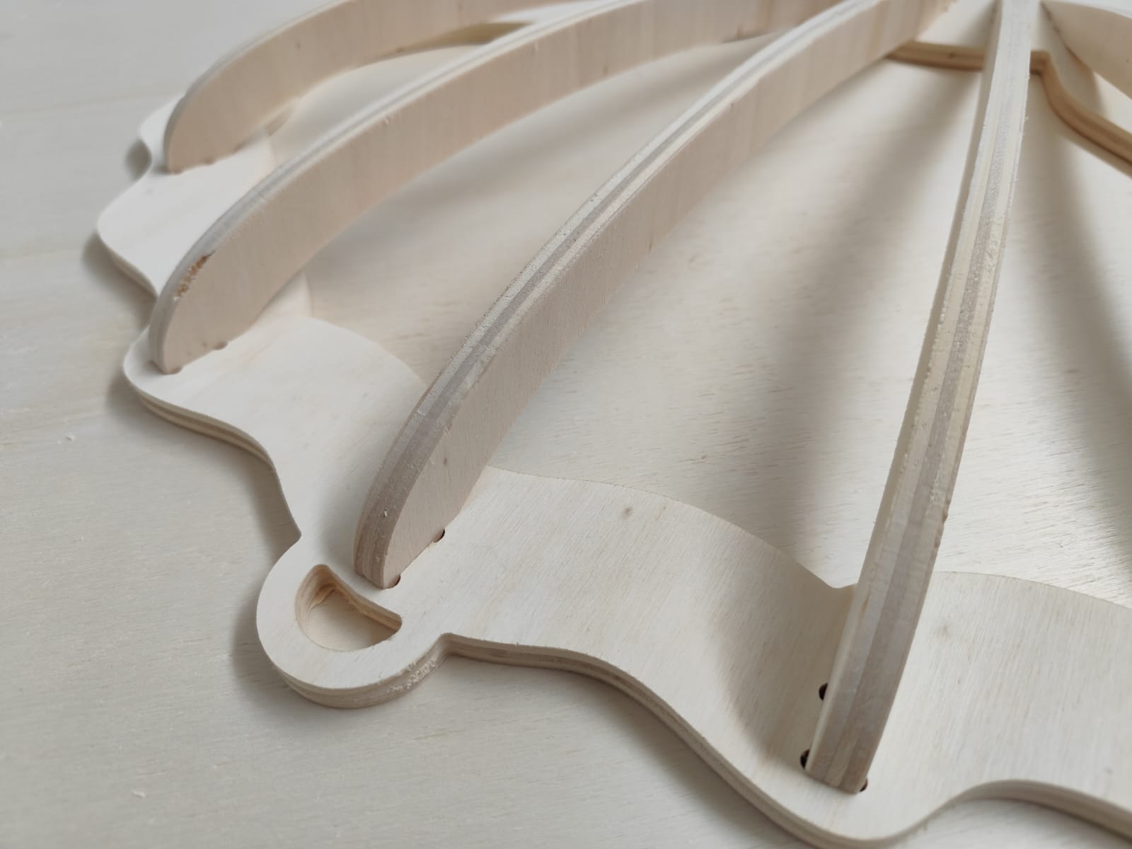
The two shells I cutted are for mounting in the wall as lamps.
Lessons learned
- Setting tool right can provide you with a great deal of precision like using the right bit.
- Lack of attention to detail is not forgiving which leads to serious safety issues to waste a large amount of resources given the scale.
- Finally, this tool saves a lot of time I just think how long and how dificult would be to do this with a jigsaw saw.
Learning outcomes
- Demonstrate 2D design development for CNC milling production
- Describe workflows for CNC milling production
- Have you answered these questions?
- Linked to the group assignment page
- Documented how you designed your object (something big)
- Documented how you made your CAM-toolpath
- Documented how you made something BIG (setting up the machine, using fixings, testing joints, adjusting feeds and speeds, depth of cut etc.)
- Described problems and how you fixed them
- Included your design files and ‘hero shot’ of your final product