Programming
- Browse through the data sheet for your microcontroller
- Write a program for a microcontroller, and simulate its operation, to:
- interact (with local input &/or output devices)
- communicate (with remote wired or wireless connections)
- Extra credit:
- test it on a development board
- try different languages &/or development environments
From the analysis of the group assignment, I finally chose the Seeed Studio XIAO ESP32C3 board, which has a wireless communction function, a faster processor, and a larger memory than RP2040.
1. Data sheet
The data sheet can be found from the offical website: https://wiki.seeedstudio.com/XIAO_ESP32C3_Getting_Started/
The basic functions of the board have already been analyzed in the group assignment, so the following part will focus on the information need for connecting components later, like function of the connection pins.
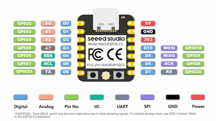
Pinout diagram
- Pin D0, D1 and D2 can be used for analog input
- Pin D4 and D5 can be used for I2C communction
- Pin D6 and D7 can be used for UART communction
so for the normal digital I/O connection, avoid using those pins, considering D3, D8, D9 and D10 first.
2. Programing and simulation
To make it easier to test the program and observe the results, we can use an online simulator for testing.
Online simulator allows us to run and debug code without physical hardware, and easily save and share projects with others.
The online simulator I used is Wokwi, which is a powerful simulator supporting many kinds of microcontroller, including XIAO ESP32C3, and also support for different kind of programming languages, such as Arduino, Micropython, Circuitpython, Rust, etc.
Wokwi online simulator: https://wokwi.com/
To start our programming simulation,
I. find the ESP32 family
II. find the XIAO ESP32-C3
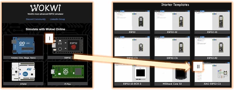
There will be a default basic example, with 3 blinking LEDs: https://wokwi.com/projects/410433244849526785
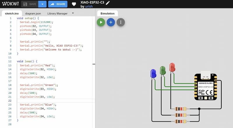
2.1 Simulation : Interacting (3 Input and 3 Output)
I want to build a interacting test, with 3 input (RGB buttons) and 3 output (RGB LEDs). Each botton will control the LED with same color. Compare to the demo, I need to add two more buttons.
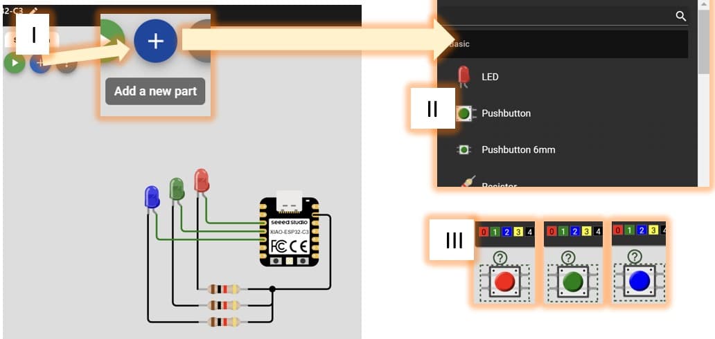
We can add the component by
I. clicking the + botton
II. find the componets you need
III. after clicking the componets, change their color by the color bar above them
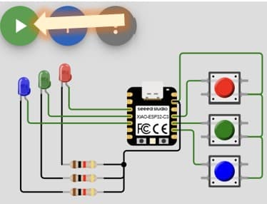
- Push button should be connected by using the two diagonal pins.
- LED have positive and negative terminals, pay attention to the connect direction. (Typically, the longer leg is the positive (+) while the shorter is the negative (-))
Programming detail
We can mark note just behind //.
void setup() {
  Serial.begin(115200);
  pinMode(D2, OUTPUT);
  pinMode(D3, OUTPUT);
  pinMode(D4, OUTPUT);
  pinMode(D10, INPUT_PULLUP); //set as INPUT_PULLUP, which mean active the pullup resistor inside the microcontroller, avoiding the short circuit when the button is pressed.
  pinMode(D9, INPUT_PULLUP);  //when pin is set as pull up, the digital read result will always be 1
  pinMode(D8, INPUT_PULLUP);  //and only become 0 when the button is pressed.
}

void loop() {
  if (digitalRead(D10)==0){digitalWrite(D2, HIGH);} //
  else { digitalWrite(D2, LOW);}

  if (digitalRead(D9)==0){digitalWrite(D3, HIGH);}
  else { digitalWrite(D3, LOW);}

  if (digitalRead(D8)==0){digitalWrite(D4, HIGH);}
  else { digitalWrite(D4, LOW);}
}
Result: https://wokwi.com/projects/424317095939542017
2.2 Simulation: Communication (Wireless connections)
Although the XIAO ESP32C3 has a build-in wifi, it's hard to test this function through the online simulator.
As an alternative, I use an IR remote and receiver to simulate wireless capabilities.
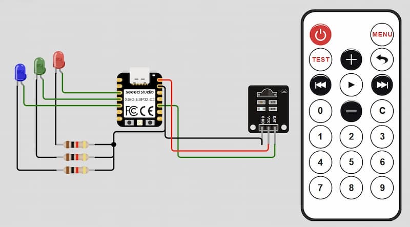
IR remote: https://docs.wokwi.com/parts/wokwi-ir-remote
IR receiver: https://docs.wokwi.com/parts/wokwi-ir-receiver
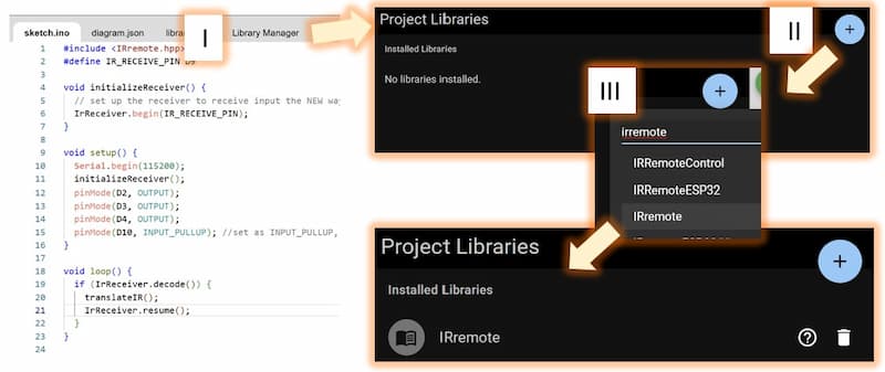
We need to install library to active the IR series command.
I. Click the Library Manager botton
II. Click the + botton
III. Find the IRremote
The function is like this:
- Press
1to opne LED red - Press
2to opne LED green - Press
3to opne LED blue - Press
powerto close all LED
Programming detail
#include <IRremote.hpp>

void setup() {
  Serial.begin(115200);
  IrReceiver.begin(D9); //set pin and initialize the receiver
  pinMode(D2, OUTPUT);
  pinMode(D3, OUTPUT);
  pinMode(D4, OUTPUT);
  pinMode(D10, INPUT_PULLUP); //set as INPUT_PULLUP, which mean active the pullup resistor inside the microcontroller, avoiding the short circuit when the button is pressed.
}

void loop() {
  if (IrReceiver.decode()) { //do something when signal reveived
    translateIR(); //pair the signal to the result
    IrReceiver.resume(); //move on to the next signal
  }
}

void translateIR() {
  // Takes command based on IR code received
  // The case code can be checked by the datasheet of the receiver: https://docs.wokwi.com/parts/wokwi-ir-remote
  switch (IrReceiver.decodedIRData.command) {
    case 162: //Power button
      Serial.println("Off");
      digitalWrite(D2, LOW);
      digitalWrite(D3, LOW);
      digitalWrite(D4, LOW);
      break;
    case 48: //Button 1
      Serial.println("num: 1");
      digitalWrite(D2, HIGH);
      break;
    case 24: //Button 2
      Serial.println("num: 2");
      digitalWrite(D3, HIGH);
      break;
    case 122: //Button 3
      Serial.println("num: 3");
      digitalWrite(D4, HIGH);
      break;
  }
}
Result: https://wokwi.com/projects/424330366096839681
3. Extra credit:
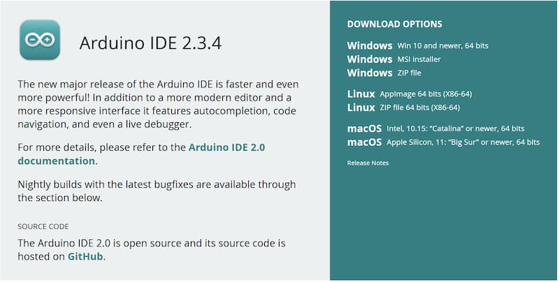
3.1 Testing on development board - Arduino IDE

-
Software Installation: Visit the Arduino website and download the installer.
-
After install the IDE, we need to install the ESP32 series board
I. go to the left bar and click the "board icon"
II. find esp32 at the BOARD MANAGER bar
III. install the esp32 (by Espressif)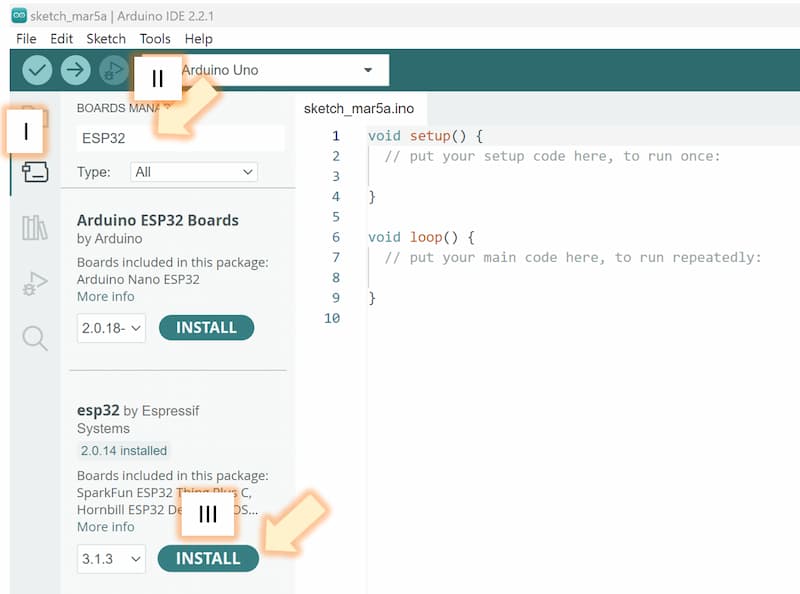
-
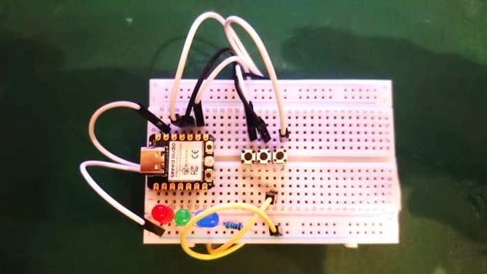
Perpare the hardware. Here I just used the same components and connection as Simulation 2.1 above.
-
After connect the development board to the computer, we need to confirm the model of the development board is mateched
I. Check the model of the development board, for me I usedXIAO_ESP32C3.
II. If the model doesn't match, click to change it
III. Find the correct model and port -
Upload a sample program
I. Open the file:File➜Examples➜01.Basics➜Blink
II. As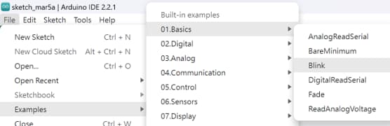
XIAO_ESP32C3don't has a built-in LED, so change allLED_BUILTINintoD2Programming detail
void setup() {
  pinMode(D2, OUTPUT);
}
void loop() {
  digitalWrite(D2, HIGH);  // turn the LED on (HIGH is the voltage level)
  delay(1000);                      // wait for a second
  digitalWrite(D2, LOW);   // turn the LED off by making the voltage LOW
  delay(1000);                      // wait for a second
}
III. Upload the program by click the
Uploadicon or pressCtrl+U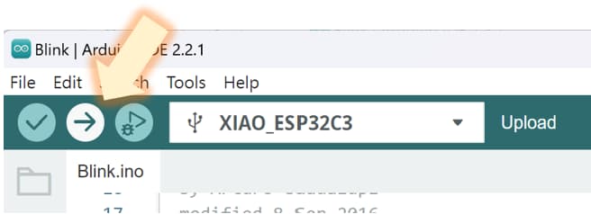
Check the result:
- Test my program
This time I used the same program as Simulation 2.1 above.
Check the result:
3.2 Different languages - Python
In wokwi, we can also use python as the program language. Here are samples to use python to program:
LED blink in python
Result: https://wokwi.com/projects/424553688559613953
LED blink in python
from machine import Pin
from time import sleep

# Define the LED pin
ledR = Pin(4, Pin.OUT)  # Use correct gpio

# Blink the LED in a loop
while True:
 ledR.value(0)   # Turn the LEDR depend on inputR
 sleep(1)
 ledR.value(1)   # Turn the LEDG depend on inputG
 sleep(1)
3 Inputs and 3 Outputs (Simulation 2.1 above)
Result: https://wokwi.com/projects/424553181367533569
3 I/O in python
from machine import Pin
import time

# Define the LED pin
ledR = Pin(4, Pin.OUT)  # Use correct gpio
ledG = Pin(5, Pin.OUT)  # Use correct gpio
ledB = Pin(6, Pin.OUT)  # Use correct gpio
buttonR = Pin(10, mode=Pin.IN, pull=Pin.PULL_UP)
buttonG = Pin(9, mode=Pin.IN, pull=Pin.PULL_UP)
buttonB = Pin(8, mode=Pin.IN, pull=Pin.PULL_UP)

# Blink the LED in a loop
while True:
 ledR.value(not buttonR.value())   # Turn the LEDR depend on inputR
 ledG.value(not buttonG.value())   # Turn the LEDG depend on inputG
 ledB.value(not buttonB.value())   # Turn the LEDB depend on inputB