Interface and application programming
- write an application that interfaces a user with an input &/or output device that you made
TJC HMI Touch Screen
HMI (Human-Machine Interface) touch screens are user interface devices that allow operators to interact with machines and systems through a graphical display. The version used here can connect to the development board directly throught UART communication method(TX and RX). The current HMI touch screen has two versions, one is Nextion Version, the other is TJC Version. Both of the hardware and the software is similar, but the TJC version support Chinese language to work in China only. Nextion is the international Version, it can connect the Nextion Editor smoothly in English. As our region is in China, the following assignment is using the TJC version.
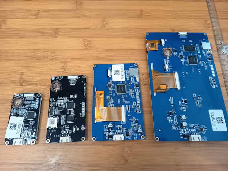
Hardware
Different size of the HMI screen
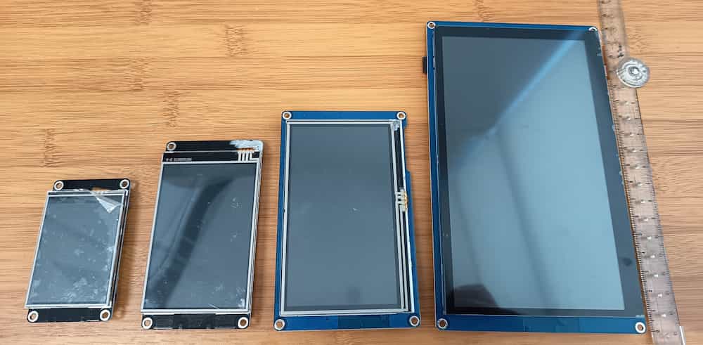
- The first 4 number after TJC mean the resolution of the model, For example, TJC3224 mean the screen is 320 pixel(horizontal) X 240 pixel(vertical)
- The 2 digital after the 4 resolution number mean the serial number, like K0, X3, X5..., different serial having a differnet specification, see the offical webpage
- The 2 number after the serial number is the size in inch. 24 mean 2.4 inch, 35 means 3.5 inch...
- The 011 after the dash is the hardware version. Both of the examples are version 11
- The letter(s) after the 011 means the type of touch screen, R means Resistive and C means Capacitive.
Default Sample Testing
The touch screen already have a default programmed interface in it, we can first have a try to see whether the screen is working.
The default screen and effect may not be the same in different type of the HMI screen.
Connection
Customize the interface
Software used
The software used for TJC version is USART HMI.

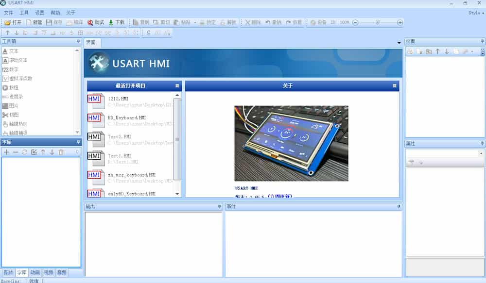
Basically the interface of the software of
USART HMI and NEXTION EDITOR is the same, just different in language.First of all, build up a basic interface and try to upload it to the screen.
Details
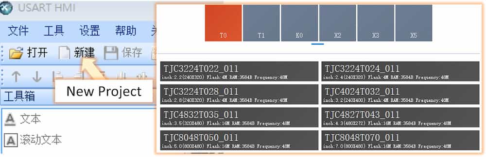
New Project(新建) button and a new interface will appear. and choose the correct model of the screen to start.
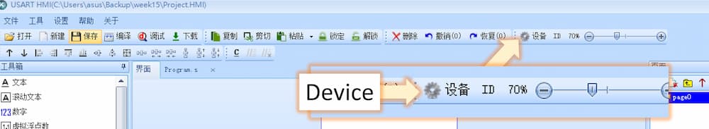
Device(設備) button to adjust.Before next step, it will be better to create a font data as there are no font data in default. If there aren't any font data, all the font in the project can't be shown.
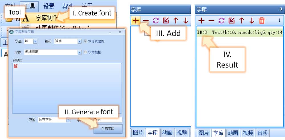
- I.
Tool(工具)⮕Create font(字庫制作) - II. You can choose the font you need here. After finish, click the
Generate font(生成字庫)to create a font data file. - III. Add the font data file just create to the
Font(字庫)section by click the+mark - IV. If the data is showed, the addition of the font data process is finished.
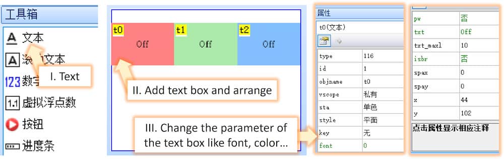
- I. Choose the type of function box you need in the interface. I add a text box for example.
- II. You can arrage the position by drag the boxes.
- III. The parameter of the box can be adjusted in the property area at the right bottom corner.
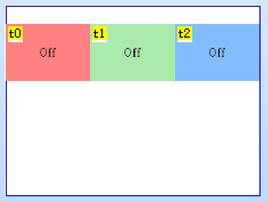
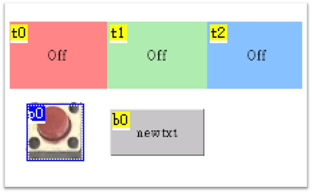
A sample of the interface with three text boxes.
Details
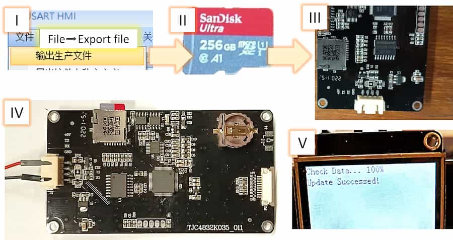
- I.
File(文件)⮕Export file(輸出生產文件)to export the interface data in.tftformat - II. save the above
.tftfile into a micro SD card - III. Power off the touch screen and insert the micro SD card into the touch screen
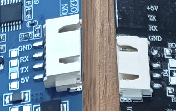
- IV. Power on the touch screen (connect the power wire to
+5Vpin andGNDpin) - V. When power on, the scree will start the uploading process.
After the Update Successed! is showed, remove the power and remove the SD card. The interface data is uploaded into the screen and when the power is on next time, it will show the new interface data.
There might be some common error during the uploading process:
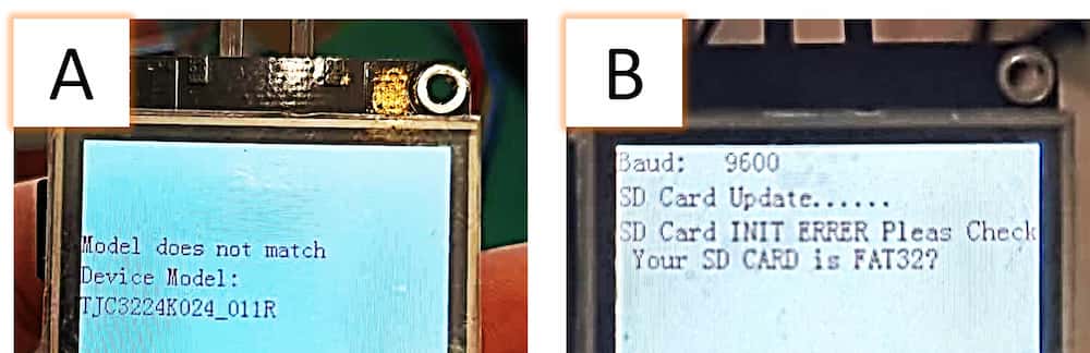
- A: You choose wrong model in the software, adjust the model in
Device(設備)and upload again. - B: The SD card format isn't
FAT32format, format the SD card inFAT32form and upload again.
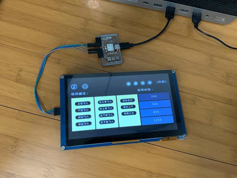
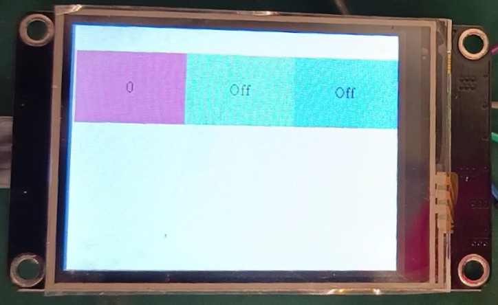
The screen after the data is uploaded.
Control the screen from the development board
Start from this section, the screen will communicate to the development board with UART communication, which mean it will use a TX and RX pin to communicate to the development board.
As the default TX(D6)RX(D7) is used to communicate to the computer when uploading program, it will conflict when the pin is connecting to the screen and fail upload.
To make the process easier, we can set a extra RXTX by <HardwareSerial.h>, creating a new TXRX and named it as TJC in the program. (Actually same meaning as Serial1).
In the following examples, D0 will set as TX1 and D5 will set as RX1.
The D0(TX1) should connect to the RX pin on the screen, and D5(RX1) should connect to the TX pin on the screen.
We can send variables or change parameters within the touch screen without installing any library by ArduinoIDE, same as button presses, page switches, and value updates. Below is an example of changing the text on t0 object from "Off" to "On"
Sample code
#include <HardwareSerial.h>
HardwareSerial TJC(1);

void setup() {
  TJC.begin(9600, SERIAL_8N1, D5, D0); //Set a new Serial1 name as TJC
}

void loop() {
  TJC.print("t0.txt=");
  TJC.print("\"");
  TJC.print("On");
  TJC.print("\"");
  TJC.write(0xff);  // We always have to send this three lines after each command sent to the nextion display.
  TJC.write(0xff);
  TJC.write(0xff);
}
And here is an example to use the three buttons on the development board to change the state of the three text on the RGB text box.
Sample code
#include <HardwareSerial.h>
HardwareSerial TJC(1);
const int TJCtx = D0;
const int TJCrx = D5;
char str[100];

void setup() {
  Serial.begin(9600);
  TJC.begin(9600, SERIAL_8N1, TJCrx, TJCtx);  //Set a new Serial1 name as TJC
  pinMode(D2, OUTPUT);
  pinMode(D3, OUTPUT);
  pinMode(D4, OUTPUT);
  pinMode(D10, INPUT_PULLUP);  //set as INPUT_PULLUP, which mean active the pullup resistor inside the microcontroller, avoiding the short circuit when the button is pressed.
  pinMode(D9, INPUT_PULLUP);   //when pin is set as pull up, the digital read result will always be 1
  pinMode(D8, INPUT_PULLUP);   //and only become 0 when the button is pressed.
}

void loop() {
  if (digitalRead(D10) == 0) {
    digitalWrite(D2, HIGH);
    TJC.print("t2.txt=");
    TJC.print("\"");
    TJC.print("On");
    TJC.print("\"");
    SendEnd();
  } else {
    digitalWrite(D2, LOW);
    TJC.print("t2.txt=");
    TJC.print("\"");
    TJC.print("Off");
    TJC.print("\"");
    SendEnd();
  }

  if (digitalRead(D9) == 0) {
    digitalWrite(D3, HIGH);
    sprintf(str, "t1.txt=\"On\"");
    TJC.print(str);
    SendEnd();
    delay(100);
  } else {
    digitalWrite(D3, LOW);
    sprintf(str, "t1.txt=\"Off\"");
    TJC.print(str);
    SendEnd();
  }

  digitalWrite(D4, !digitalRead(D8));
  sprintf(str, "t0.txt=\"%d\"",!digitalRead(D8));
  TJC.print(str);
  SendEnd();
}


void SendEnd() {
  TJC.write(0xff);  // We always have to send this three lines after each command sent to the nextion display.
  TJC.write(0xff);
  TJC.write(0xff);
}
The testing result:
Control the development board from the screen
We can set the screen boxes to send a signal while it's been pressed or released. Also we can set the action after they have been pressed.
Details
To make it easier to look, I add a picture box p0 with a button picture, a button box b0.
t0 text box change to 1 when I press the p0 button picture, I can set the program t0.txt="1" at the Event when pressed(按下事件) of the p0 box.Here I add different event to change the text and background color of the text boxes t0, t1 and t2 when the boxes p0,b0 and t2 is pressed or released.
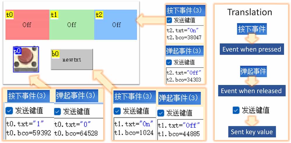
Remeber to tick the Set key value box if you want the development board to receive the signal of the event.
We can see the simulated reaction result by press the Simulation(調試) button.
The testing result in the USART HMI software:
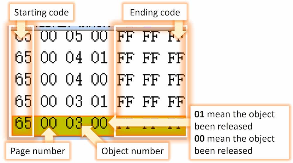
If the Set key value box is clicked in the software, the screen will set a singal to the development board when the event actived. The format is like the following:
Details
The code:
#include <HardwareSerial.h>
HardwareSerial TJC(1);
const int TJCtx = D0;
const int TJCrx = D5;
const int ledr = D4;
const int ledg = D3;
const int ledb = D2;
const int inr = D10;
const int ing = D9;
const int inb = D8;
int var = 0;
char str[100];
char lstring[32];
void setup() {
  Serial.begin(9600);
  TJC.begin(9600, SERIAL_8N1, TJCrx, TJCtx);  //Set a new Serial1 name as TJC
  pinMode(ledr, OUTPUT);
  pinMode(ledg, OUTPUT);
  pinMode(ledb, OUTPUT);
  pinMode(inr, INPUT_PULLUP);  //set as INPUT_PULLUP, which mean active the pullup resistor inside the microcontroller, avoiding the short circuit when the button is pressed.
  pinMode(ing, INPUT_PULLUP);  //when pin is set as pull up, the digital read result will always be 1
  pinMode(inb, INPUT_PULLUP);  //and only become 0 when the button is pressed.
}

void loop() {
  if (TJC.available() > 0) {
    lstring[var] = TJC.read();
    lstring[var] += '0';
    Serial.print(lstring[var]);
    var++;
  }
  if (var >= 7) {
    var = 0;
    Serial.println("end");
    Serial.print(lstring[2]);
    Serial.println(lstring[3]);
    if (lstring[2] == '5') {
      if (lstring[3] == '1') { digitalWrite(ledr, HIGH); }
      if (lstring[3] == '0') { digitalWrite(ledr, LOW); }
    }
    if (lstring[2] == '4') {
      if (lstring[3] == '1') { digitalWrite(ledg, HIGH); }
      if (lstring[3] == '0') { digitalWrite(ledg, LOW); }
    }
    if (lstring[2] == '3') {
      if (lstring[3] == '1') { digitalWrite(ledb, HIGH); }
      if (lstring[3] == '0') { digitalWrite(ledb, LOW); }
    }
  }
}
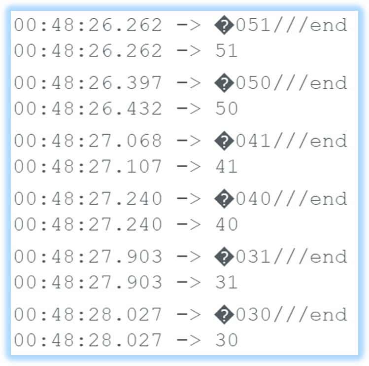
We can use the Serial.read(), or the custom TJC.read() to set the received signal into a variable. The signal is showed in seven code, ending with ///. We can determine the signal is sent by which touch boxes by the object code (the third code), and what is the event action by the event code (the forth code).
Here is the signal received from the screen:
The example above is a simple application that don't need to use any library. For more complicated programming, you can try to use the Nextion library, which is compatible in both TJC and Nextion series.
Nextion library tutorials