Mechanical design & machine design
Project Overview
 The WordMiser Oracle
"The WordMiser Oracle" is a cross-space collaboration project, connecting the SenseCAP Watcher AI assistant from the Chaihuo Maker Space in Shenzhen, with the typewriter machine at the Macau Science Center in Macao, creating a unique interactive experience.
The core concept of this project is to create an "AI oracle that write words," which must limit its responses to 30 characters (adjusted to 25 characters based on our actual tests) and physically write them out by the typewriter machine.
The project can be divided into following phases:
- Phase 1: Build up the hardware
- Phase 2: Wireless communction
- Phase 3: Further improvement
Individual contribution:
My role is mainly focus on the hardware design, building up and upgraded.
Build up the hardware
Data research
In phase 1, our target is building up the basic writing/drawing machine, with the function to input a text or picture and let the machine write / draw it out. For this purpose, I had a research on different type of machine:
Comparing structure
The purpose of the machine is holding a pen to write, which is similar to using a arm to hold thing, similar as a robotic arm. So first we analysis some common types of robotic arm.
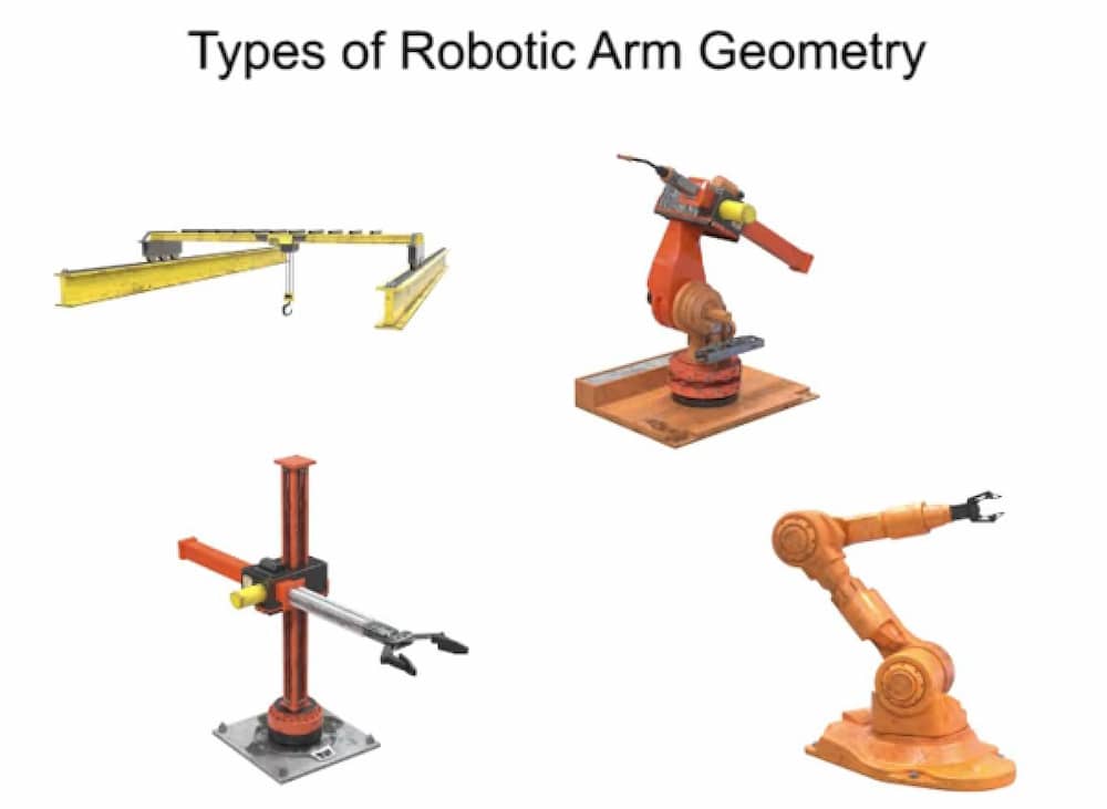
And our final choice is Cartesian coordinate robot structure. The working principles of this type of machine is similar to CNC machines, which is controlling an end efforter to go to a specific coordinates. As the X and Y axis is working in linear separately, it is easy for building up, controlling and programing.
We found that in last year, Chaihuo Maker Space had also built up a writing machines, which is also a Cartesian coordinate robot structure.
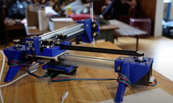
Reference: https://fabacademy.org/2024/labs/chaihuo/docs/assignment/week-10mechanical-design-machine-design./
But the a two bar structure is not suitable for long distance transportation (as we need to take the machine from Shenzhen to Macao), and it need a quite large spare space whiling operating.
Although the work structure is still a bit lacking, the components used in the machine generally meet our requirements. Therefore, we plan to reuse some parts and refer to other structures, like the alumimum bar and gear belts.
We find another good structure sample, a laser machine project(https://www.instructables.com/CNC-50mW-Laser-Engraver/). The base stucture is very stable, and the size is smaller. We decide the machine is writing on A4 paper, so the size is fit. So we will build up the basic stucture of the machine refer on it, and design a pen holder adding on it to hold the pen.
As we want to spend more time for the improventment and application, we want to limit the time wasted on the machine building, we hope to assemble the machine using existing resources as much as possible.
Here is the resources we found in the Labs:
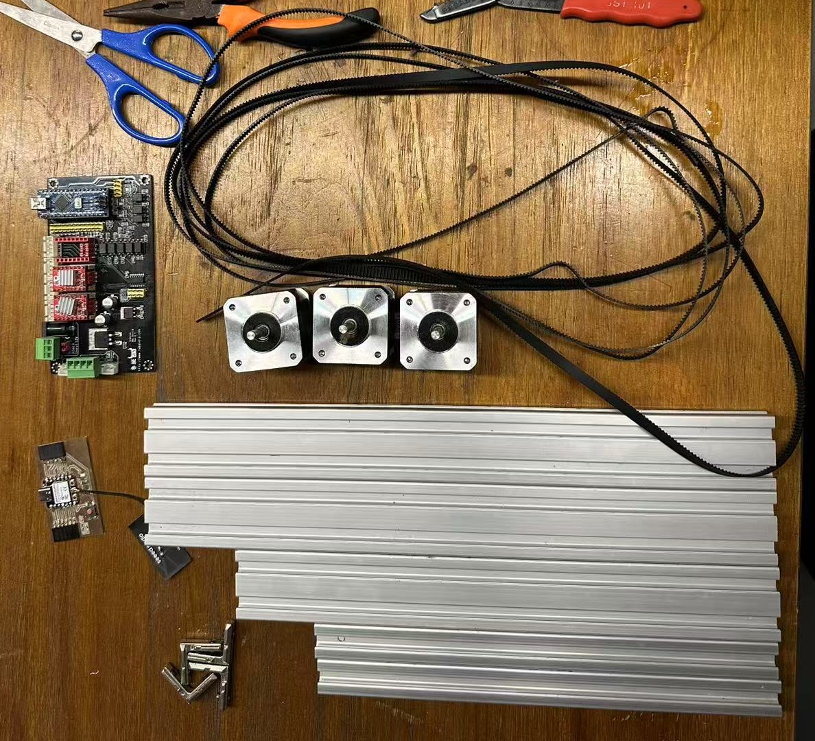
Specification
| Component | Specification | Quantity |
|---|---|---|
| MCU | Arduino Nano | 1 |
| Arduino CNC Shield | Rev2.7 | 1 |
| Stepper motor | Nema 17 | 3 |
| Stepper Motor Driver | A4988 | 2 |
| Servo Motor | MG90S | 1 |
| Alumimum bar | 20 * 20 * 25cm | 2 |
| Alumimum bar | 20 * 40 * 35cm | 2 |
| Alumimum bar | 20 * 40 * 29.7cm | 2 |
| Gear belt | 6mm * 36cm | 1 |
| Gear belt | 6mm * 42cm | 2 |
| Nylon roller bearing | M6-23mm | 12 |
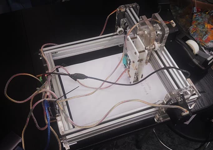
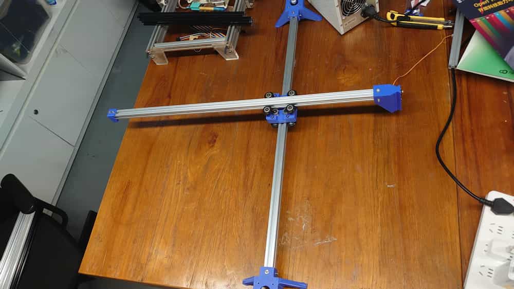
1. Building the machine
Building process
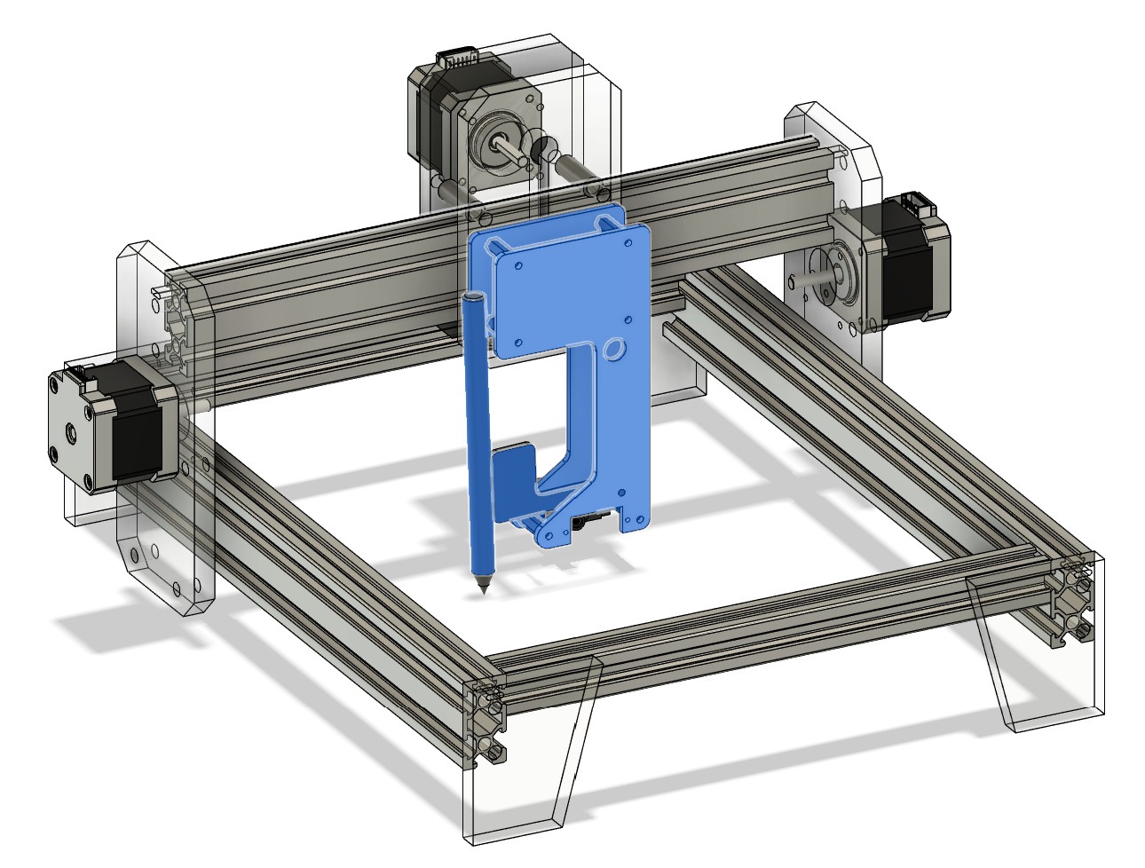
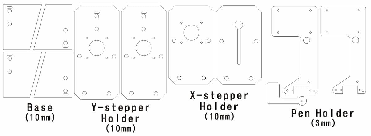
To make sure the design work, I build the 3D models of the components above in Fusion 360, and also design a pen holder using 3mm acrylic board.
Stepper model:https://grabcad.com/library/nema-17-stepper-motors-coaxial-60-48-39-23mm-1
Servo model:https://grabcad.com/library/mg90s-micro-servo-2/details?folder_id=14030136
Simulation:
The acrylic board part is export as following:
The overall result: Machine design_v1
And we build it with real components.
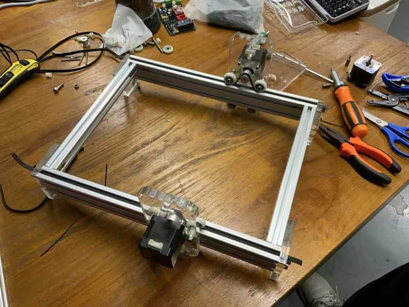
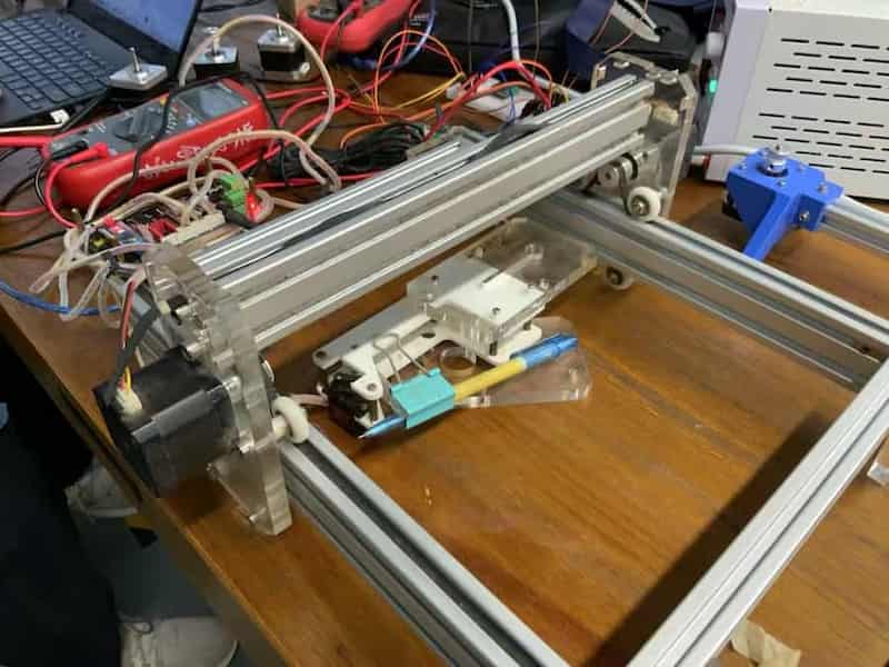
The final outlook:
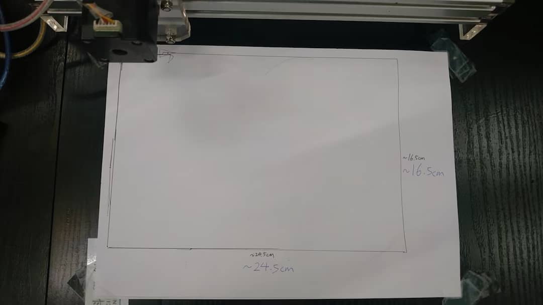
Manually printing area test
The printing area is about 24.5cm x 16.5cm
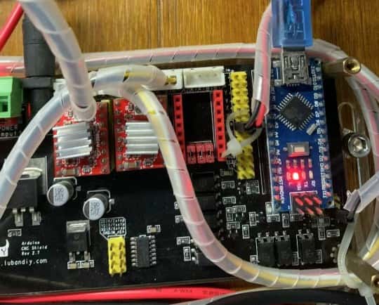
2. Firmware controlling
The MCU on the machine is arduino Nano.
Details
The firmware we used for controlling is GRBL. GRBL is a popular open-source firmware for controlling CNC machines with Arduino. It interprets G-code commands and controls the stepper motors accordingly.
The GRBL firmware can be found in Github website, and can be download to the Arduino nano board through Arduino IDE.
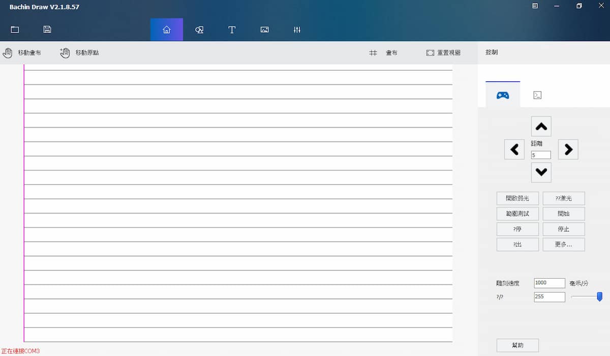
After the firmware is ready, we do test the motor by direct control from the computer. The testing software is Universal G-Code Sender '
3. Writing Testing
After the connection between the machine and computer is set, the next step is doing a text writing test.
Details
Here we use bachinmaker as the testing software, as it can easily input text, adjusting their font and size for the testing.
- First we try to write the text from the software built-in function. '
The word can be written but there are no pen up and pen down. Here are one of the sample text "off":

-
We try to add the pen up and down action with G-code is (M03 and M05), but the function is reverse.
Plug-in failedWe find a inkscape plug-in which can generate gcode control from the vector file, with the instruction: https://inkscape-manuals.readthedocs.io/en/latest/extensions.html#installing-extensions and the plug-in is: https://drive.google.com/file/d/1Kfc7F9UUtgKDv8e2ULvpZOiOcIrNbcVQ/view With the instruction, the plug-in can set the pen up action as M03 or M05, and so as the pen down action. But after the plug-in is downloaded and installed, it can't be opened in inkscape, and we had try it in different version of inkscape and different operation system(Windows and MAC OS), and both fail.
Solving method:
Our final solution os change the servo motor to another side, so the rotate direction of the servo will be reverse, and no need to change the draft controling code.
And here is the final result: writing the text with pen up and down
Here is a simple to write/draw the fablab logo of the two places:
Further improvements
During the testing, there is some improvements found, and I hope they can be improved in the future. So I designed a version 2, here is the simulation:
The improvements direction are:
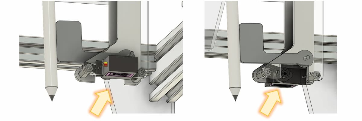
Simplify the structure of the pen holder
- Redesign the pen holder parts make the installion of the machine become easier. Also, simplify the design reduce the size of the pen holder, which can enlarge the writing area
Make the paper installation easier
- A base is added under the machine, and there is a slider board to holder the paper, so the paper can be installed to the right position easily.
Member in our team
- Chon Kit Kuok
- Hongtai Liu
- Lei Feng
- Long Wai Chan

Individual contribution
- Writing machine hardware and programming
- MQTT data receiver


Individual contribution
- Text-to-G-code conversion
- MQTT Transmission
- Project video directing and post-production

Individual contribution
- Mechanical structure 3D model design
- Hardware connection and upgrade