Solar Cooker
Welcome to my Solar Cooker Project page, I hope this can inspire more people to look to the sun for inexpensive cooking methods.
I would like to give a special thank you to Daniel Mateos, Adai Sulinach, Josep Marti, Camlia Simsiroglu and Andrew Mark, Gonzalo Guarner, Katya Castellanos and Mark Shamash for helping me significantly during the project. The Fab Academy organisation also deserve a mention. Bless you all.
Table of Contents
1. Project Vision
The one resource we will hopefully always have on Earth is the Sun. The suns rays are responsible for most life on earth providing plants and humans alike with photons, vitamin D and heat.
There are millions of people across the world without access to safe, reliable fuel for cooking in poorer parts of the world that can lead to severe health problems. In the richer parts of the world solar cooking is overlooked in favour of gas, electric or wood-fired cooking methods due to their abundance, relatively low price and convenience.
Intention is to develop an inexpensive low -tech cooking method that can be adapted into the modern lifestyle.
1.1 My current knowledge of solar cookers
My only experience with solar cookers coming into this project is a small solar cooker I visited at commune in Portugal and the Parabolic Satellite Dish I have seen used to boil water. Perhaps there is a reason we don’t have more practical ones?
1.1.1 Reasons why I think it might work
I saw somone on Instagram melting rocks with a solar ray he made from an old TV screen
https://www.instagram.com/joemyheck/reel/Cxb1QHwJ6k1/
Global understanding of laser technology is constantly improving, the same for material science, thermo-dynamics and optics.
1.1.2 Resources
Following hours of research and gaining practical experience in the FabLab vision changed considerably. The following references were imperative to understanding solar concentration:
Nonimaging Optics. (Roland Winston, Juan C. Minano etc.) [1]
Design and development of a novel and cost effective modified Compound
parabolic trough collector, Durgesh Kumar, Punit V. Gharat [2]
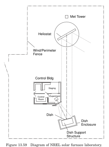
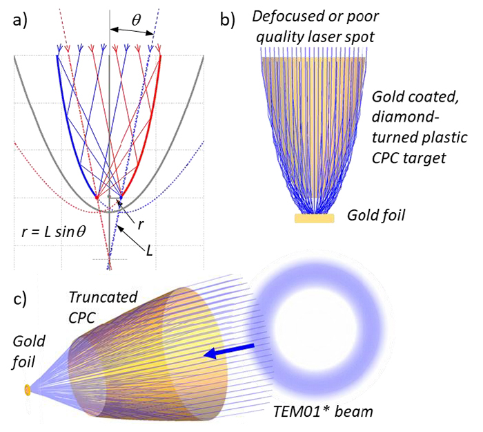
Expanded the experimental capabilities of the National Ignition Facility’s (NIF) Advanced Radiographic Capability (ARC) laser. compound parabolic concentrators (CPC), give ARC — NIF’s “laser within a laser” — the ability to produce effects associated with laser intensities more than 10 times greater than it was designed to deliver.https://www.llnl.gov/article/46096/focusing-target-gives-powerful-boost-nifs-arc [3]
Insulated Solar Electric Cooker https://wiki.lowtechlab.org/wiki/Insulated_Solar_Electric_Cooker_(ISEC) [4]
A New Approach for Design Optimization and Parametric Analysis of Symmetric Compound Parabolic Concentrator for Photovoltaic Applications by Faisal Masood 1,2,*,Perumal Nallagownden 1,Irraivan Elamvazuthi 1,Javed Akhter 3 andMohammad Azad Alam 4
https://www.mdpi.com/2071-1050/13/9/4606 [5]
Effect of Surface Radiation on Natural Convection in Parabolic Enclosures by Gerardo Diaz
https://www.tandfonline.com/doi/abs/10.1080/10407780701789518 [6]
New Methods of Reflector Design by Harald Ries, Julius Muschawek and Andreas Timinger
DOI:10.1364/OPN.12.8.000046 Optics and Photonics News 12(8): 46-49 [7]
Toward a best-form CPC-like nonimaging optical concentrator by Isaac Metcalf, Gang Chen, and Thomas A. Cooper . Optics Express • Vol. 30, • Issue 25, • pp. 44556-44568 • (2022) https://doi.org/10.1364/OE.476189 [8]
Performance of compound parabolic concentrators with polygonal apertures by
Thomas Cooper, Fabian Dähler, Gianluca Ambrosetti, Andrea Pedretti, Aldo Steinfeld. Solar Energy Volume 95, September 2013, Pages 308-318 https://doi.org/10.1016/j.solener.2013.06.023 [9]
https://kusudama.me/#tutorials/HowTo [10]
Preliminary investigation on optical performance of linear fresnel lens coupled compound parabolic concentrator Xueyan Zhang, Jiayue Li, Jun Chen, ei Chen
https://doi.org/10.1016/j.energy.2023.127910
https://www.sciencedirect.com/science/article/abs/pii/S036054422301304X?via%3Dihub [11]
A comprehensive review of solar cooking systems Mehmet Akif Ceviz, Burak Muratçobanoğlu, Emre Mandev, Faraz Afshari First published: 17 April 2024 https://doi.org/10.1002/wene.516 [12]
2. Conception and Design
2.1 Initial Vision, how it started
My initial vision for the cooker is:
- a hyperbolic funnel with reflective wall that is aimed at the sun;
- The suns rays are reflected onto a reflective lens:
- Light is reflected into a spherical insulated oven whose walls are made up of tiny mirrors, like a disco ball reflecting the light around the oven.
- There will be a metal mesh suspended in the middle of the oven where the user can place their food, or cooking stone.
- There will be a pizza oven type entrance for accessing the oven.

2.2 Revised Concept - Portable Solar Cooker
The aim of this project is to study the feasibility of making a light-weight portable solar cooker. This will be in the form of an experiment with the following components:
- Solar Concentrator (Compound Parabolic Concentrator)
- Cooking pot (standard cooking pan)
- Insulation (Cork to insulate the cooking pot)
- A portable electronics box which accurately measures and records the temperature of the cooking surface.
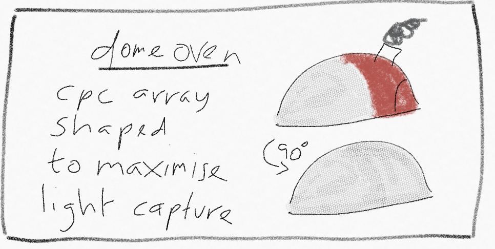
2.2.1 Solar Concentrator
The most important part of this project is the Solar Concentrator that will concentrate light rays on to a focal area, increasing the light intensity onto a cooking pot, heating it up enough to cook some food.
The majority of direct-type solar concentrators used for cooking or heating involve the reflecting light back onto a heating surface [12]. My goal is to investigate the possibility of using Compound Parabolic Concentrators (CPC), usually used to increase laser intensity in high energy systems [3], for solar cooking.
I spent over a week reading relevant material to gather an understanding of sun concentrators and non-imaging optics, and their applications. The most useful resource being Non-Imaging Optics by Roland Winston, Juan C. Minano and Pablo Benitez from Elsevier academic press [1].
2.2.1.1 Compound Parabolic Concentrator, Fundamentals
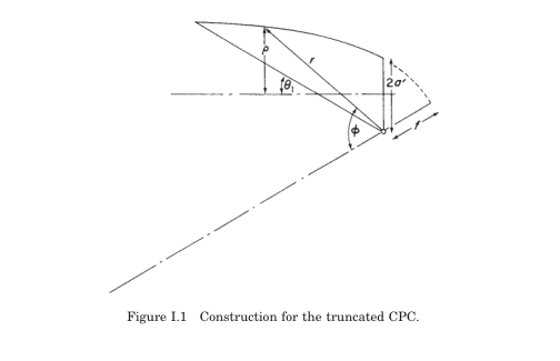
CPCs use the edge-ray principle assuming all rays entering the aperture at the maximum acceptance half-angle (these are the "extreme rays") should, after one reflection (or no reflection if they pass directly), be directed to the edge of the exit aperture (the absorber).
Compound Parabolic Concentrators CPC, are mathematical parabolas oriented, positioned (specifically their foci), and truncated to achieve the desired light collection properties. Equations described by Rabl and Winston referenced in [1] are their mathematical formulation.
Once I had a significant understanding of the terminology and concepts I noted the key parameters for the design process:
- Exit Aperture,
- Acceptance demi-angle,
- Length of the CPC,
- Truncated length of the CPC,
2.2.1.2 CPC optimisation for experiment
I then used Gemini to help me determine the building the 3D model in Blender with big help from Adai. The actual history can be found here.
The conversation I had with Gemini in order to determine the python scripts for CPC choice, optimisation, troubleshooting and the steps required to build the 3D design in Blender can be found here: CPC Optimisation
For the experiment I used an 18 degree θ_a and a h_trunc of 1.0 m so that it is manageable. The expected Power generation is around 409 W assuming a solar irradiance with an optical efficiency of 0.75 for a 39cm exit aperture.
2.1.1.3 Design and Manufacture
In order to achieve the objective of an ultra light weight portable solar cooker, the CPC design is inspired from tents. The walls of the CPC are made from reflective fabric (BoPET otherwise known as MYLAR), with a tent pole like structure: the poles are made from 3mm thick fibre glass and PLA connectors have been 3D printed using the Bambu X1 Carbon.
2.2.1.3.1 Reflective Walls
2.2.1.3.1.1 Design
The parabola was created using a python script based on the edge ray principle. The input file and the script are given below.
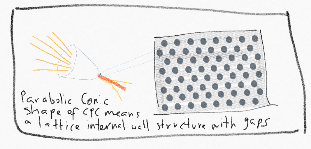
I then rotated it 360° with the “screw” modifier with 64 steps. This allowed me to mark equally distanced seams (CTRL +E → Mark SEAM) to unwrap (CTRL + E —> UNWRAP) the parabola into 8 pieces. This is only an approximation, this parabolic shape is more conic than a perfect parabola, but for this proof of concept I still hope to see the influence of solar concentration. These were then exported in the UV Editor to be modified in Rhino for the laser cutter.
These were then imported into Rhino, and the outline was traced with the help of the MAKE2D function, EXPLODING and regrouping the outline (Rhino file below). These are then laser cut in cardboard with the RayJet400 to use as a template with the Mylar.
2.2.1.3.1.1 Fabrication
The RayJet400 was used to cut out a template to be used for cutting out the mylar. We could not use it directly due to the high reflectivity of the MYLAR.
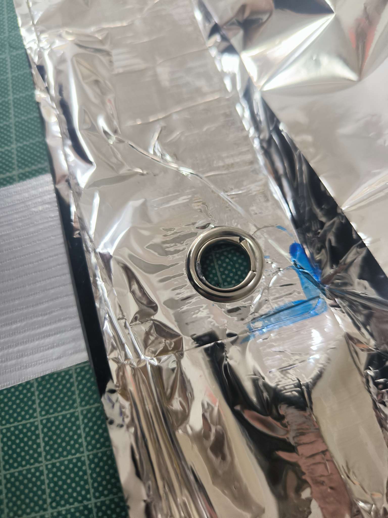
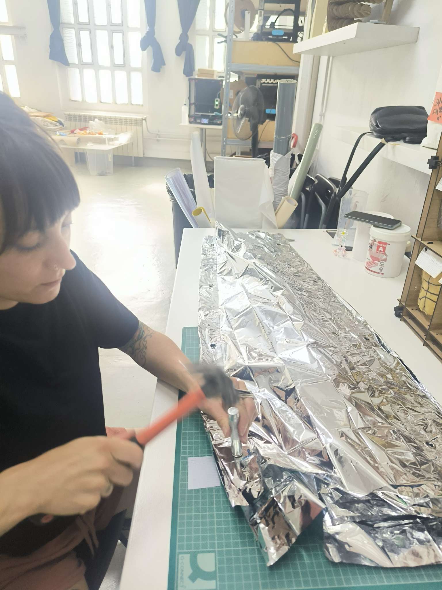
Once the pieces have been cut and scotched together (the mylar tears easily so it is not adapted to sewing, hopefully the CPC doesn’t heat up too much so the adhesive fails or the nylon catches fire!), it is time to add rivets on overhang on the vertical edges, where 40-50mm was left for this purpose.
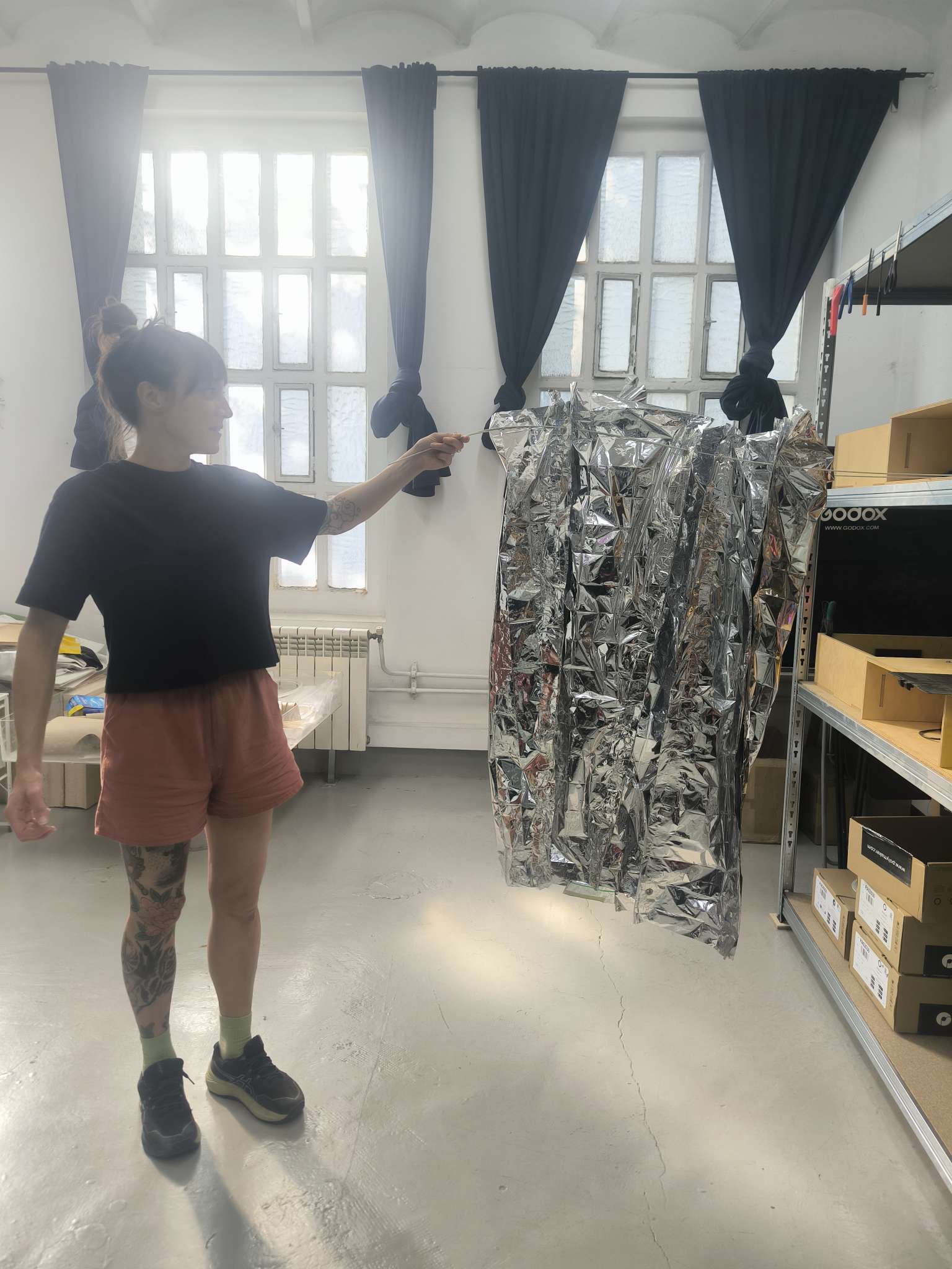
The parabola starts to take shape, and it can be stored or used as a shower curtain too!
2.2.1.3.2 Pole Connectors
The wire frame is made from taking edge cuts at various heights.
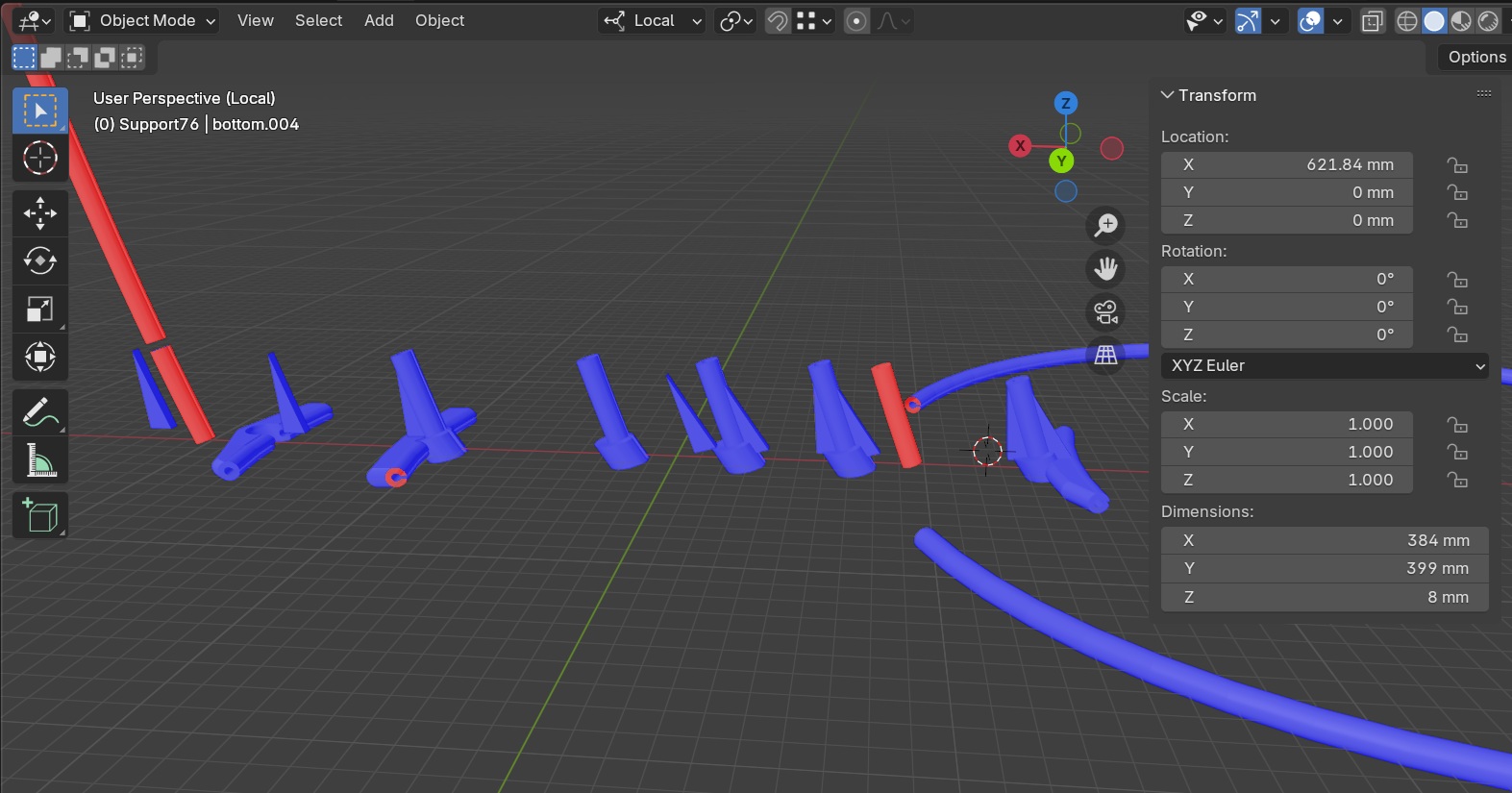
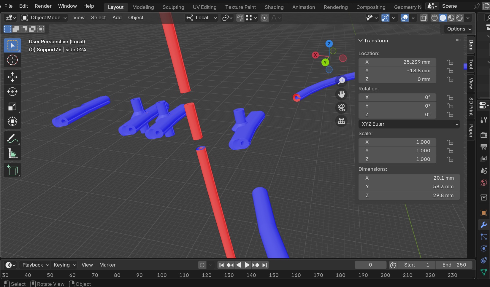
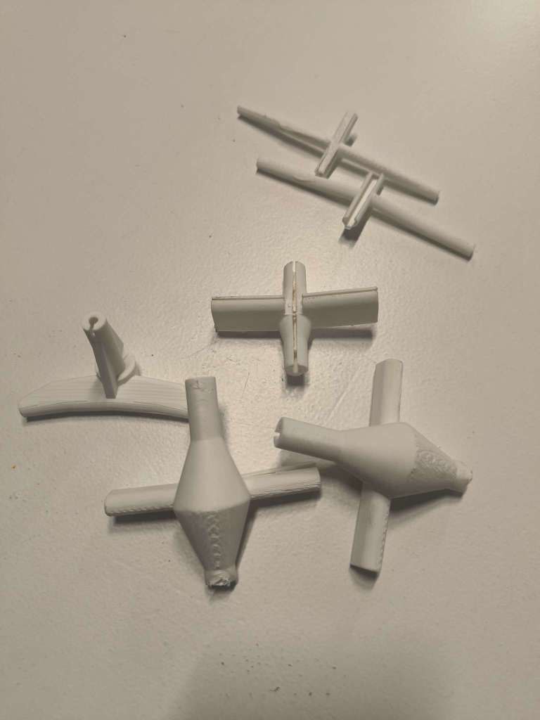
In Figure 2.12 the video shows how the connectors were created from duplicating the edge rings at heights 0, 0.33, 0.66, and 0.97 m across the height of the parabola, and duplicating the vertical parabola.
- ALT-CLICK the ring from the Z position on the parabola, duplicate, convert to curve.
- Bevel with the teardrop shape similar to that shown in Figure 2.11, with the gap orientated towards the centre of the parabola, then cut the mesh for an appropriate size of connector
The two components are then boolean unioned together so that there is space for the fibre glass wire/poles to pass through. However, the first iteration of connectors shown in Figure 2.13 were too weak.
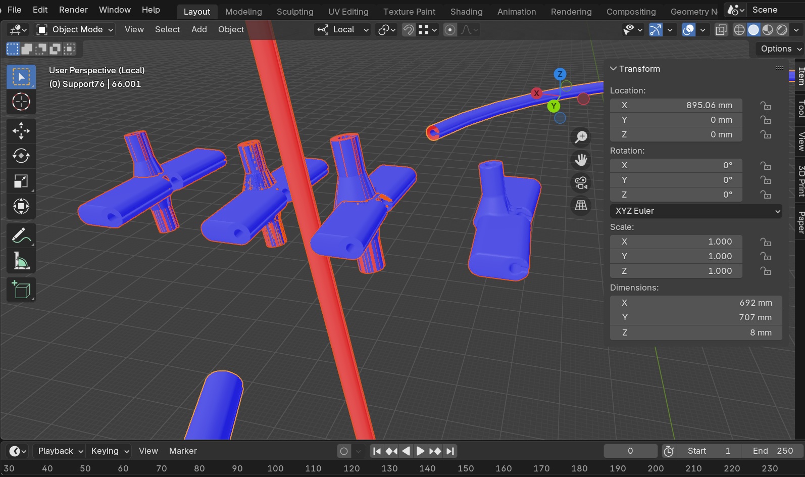
To make supports were made stronger, the following technique was adopted:
- ALT-SELECT the nodes at that height, then unselect the centre vertices with CTRL. Once only the outer-ring vertices are selected scale with S, to get the knee/knuckle like structure.
- The horizontal part was made by adding some rings vertices using CTRL-R with all the vertices selected, placing them closer to the vertical at then half way between the then end. These rings were then selected in pairs, and EXTRUDED (Select vertices to be extruded then CLICK E then X to fix orientation of extrusion) or GRABBED (Select vertices to be extruded then CLICK E then X to fix orientation of extrusion).
- Then Boolean Diff the vertical from the horizontal, delete excess vertices in centre, then the vertical knuckle was scaled slightly bigger to ensure that the boolean union between the vertical and the new horizontal is successful, as shown in the video in Figure 2.14.
From here, the 3D mesh needed to be fixed so that it can be printed correctly. This involves deleting and merging conflicting vertices within the design, until the Make Manifold option in the 3D print returns no unmanifolded areas.
This process is repeated for the other 3 connectors, the different stages are roughly shown in the Figures 2.15-2.18 below.
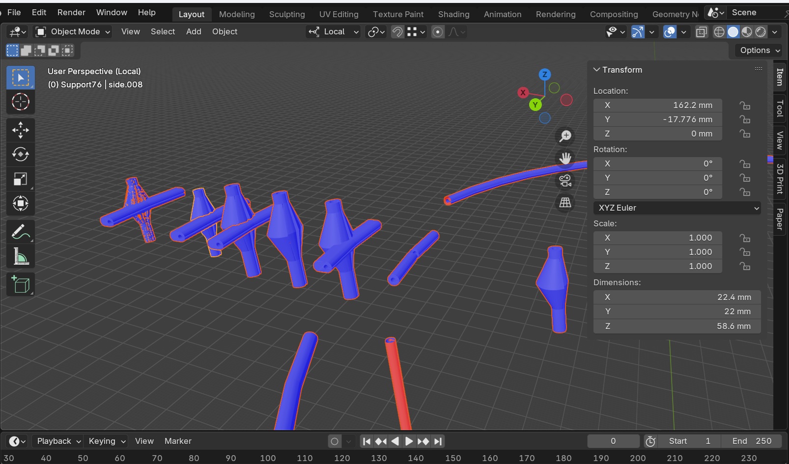
The STL files are given below, along with the initial Blender file containing only the parabola line and revolved cone, again for file size issues.
The stl files were imported into Bambu Studio, and sliced using a standard 0.2 mm layer height and quality with supports for the Bambu Carbon X1 3D printer. You can see the settings, component layout and printing time in the Figure 2.19 below along with the resulting prints in Figure 2.20. Note the improved strength and design between the initial skinny design and the newer bulky design in Figure 2.20 below.
2.2.1.4 Assembly
The final part to complete before assembly is to cut the correct lengths of fibre glass wire for each of the connector heights, and the vertical component of the parabola too. IT was decided to use 4 connectors for adequate strength, notably in order to tackle outside forces from the wind.
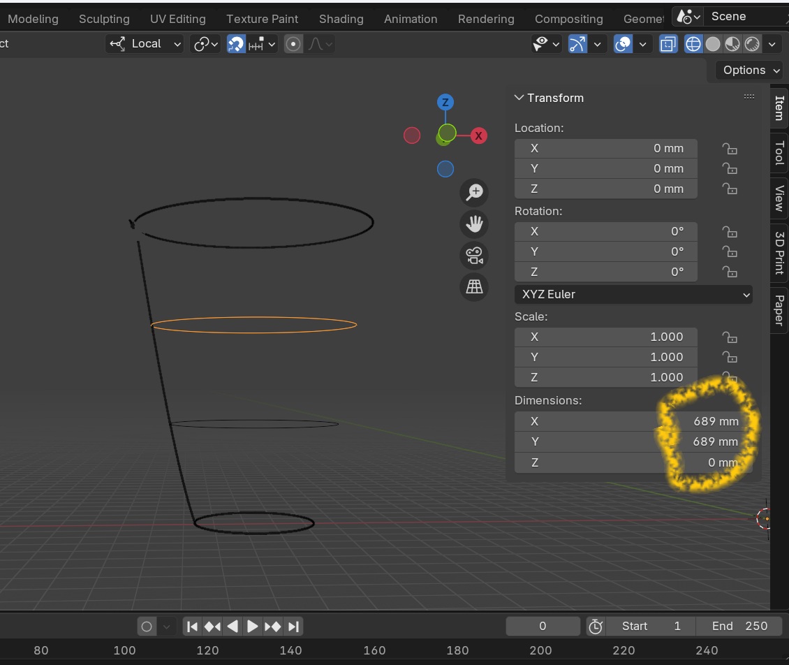
In Figure 2.21, the circumference of the edge ring at each of the connector heigts (0, 33, 66, 97 cm) was noted and adjusted. For the bottom ring, only one wire was used, where as for the other layers two wires were used. In the example in Figure 2.21, 689 mm is the diameter, Dedgering, therefore the circonference is 689 + x PI= 2136. This was divided by 2 = 1068 mm, so therefore two wires of 1068 mm are required to be used with the four connectors at z= 0.66 cm to make the perfect circle for the parabolic shape.
This process is repeated for all four connector heights.
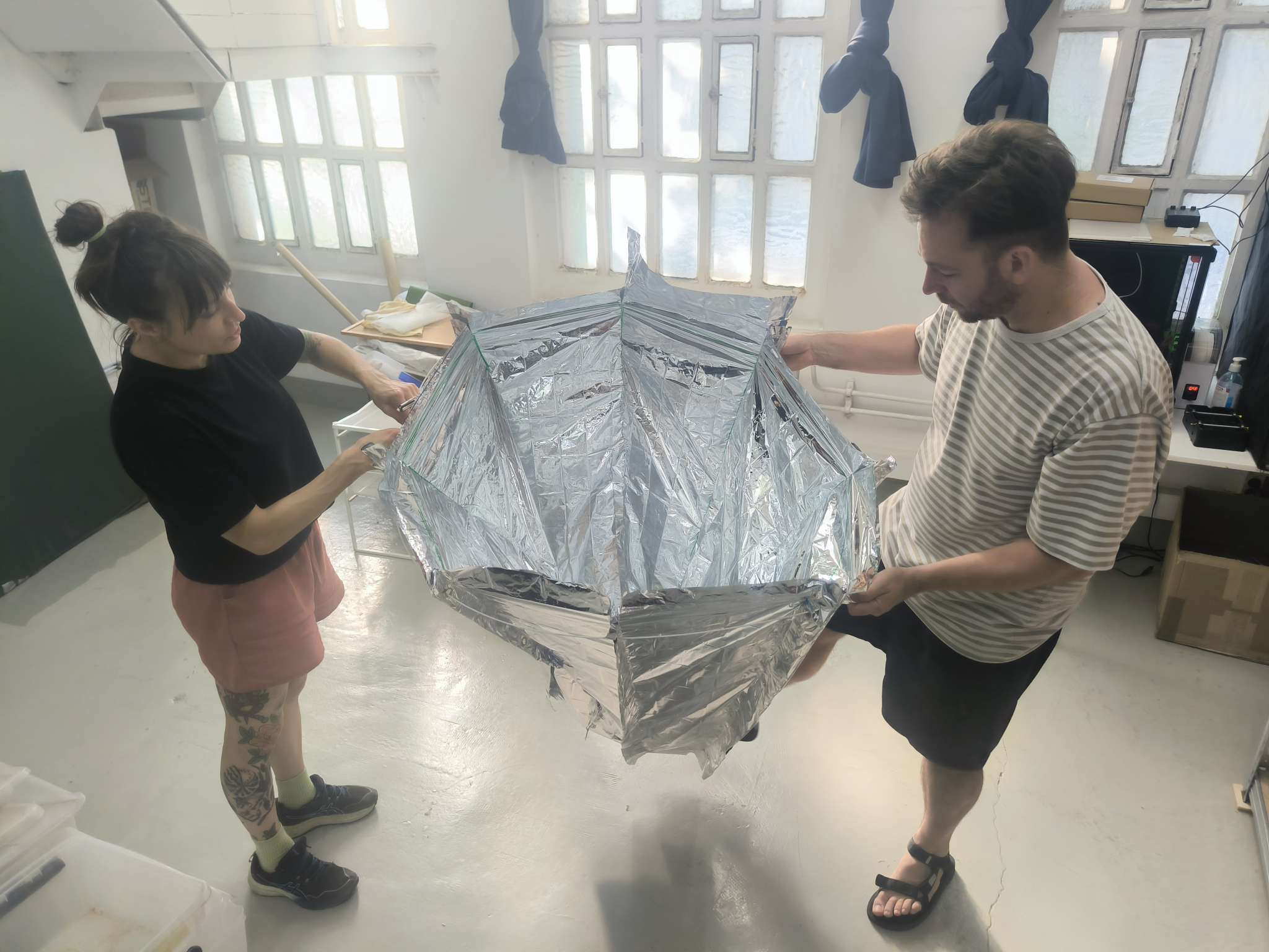
The solar concentrator was then connected together, passing the wire though the rivets of the reflective fabric walls and the vertical position was maintained by the vertical connectors and the elasticity of the wire. Figure 2.22 below shows the concentrator setup in the FabLab concentrating the light of the room at the exit.
For the top and bottom of the concentrator washing line pegs were used to make the material as taught as possible to increase surface tension.
.jpg)
2.2.1.5 Limitations and Future Improvement
The manual cutting and assembly of the MYLAR meant that surface tension was lacking. Although MYLAR has a high reflectivity, ALUPET treated with a heat gun under tension can improve reflectivity enormously. Therefore the next iteration will look to inherently provide surface tension to the reflective walls perhaps through using inflatable materials, folded aluminium sheets or perhaps even going for a more permanent design, intended for communal cooking.
2.2.2 Cooking Pan and Insulation
I decided to use the same cooking pan that I found at my apartment, a 28 cm deBuyer we seasoned steel pan. It provide a dark large cooking surface, even though it is significantly smaller than the 39 cm concentration surface at the exit aperture. This will be acceptable for the first feasibility experiments. Alighning the cooking surface with the exit aperture will surely improve efficiency and heat exchange at a later spiral.
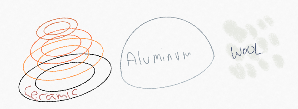
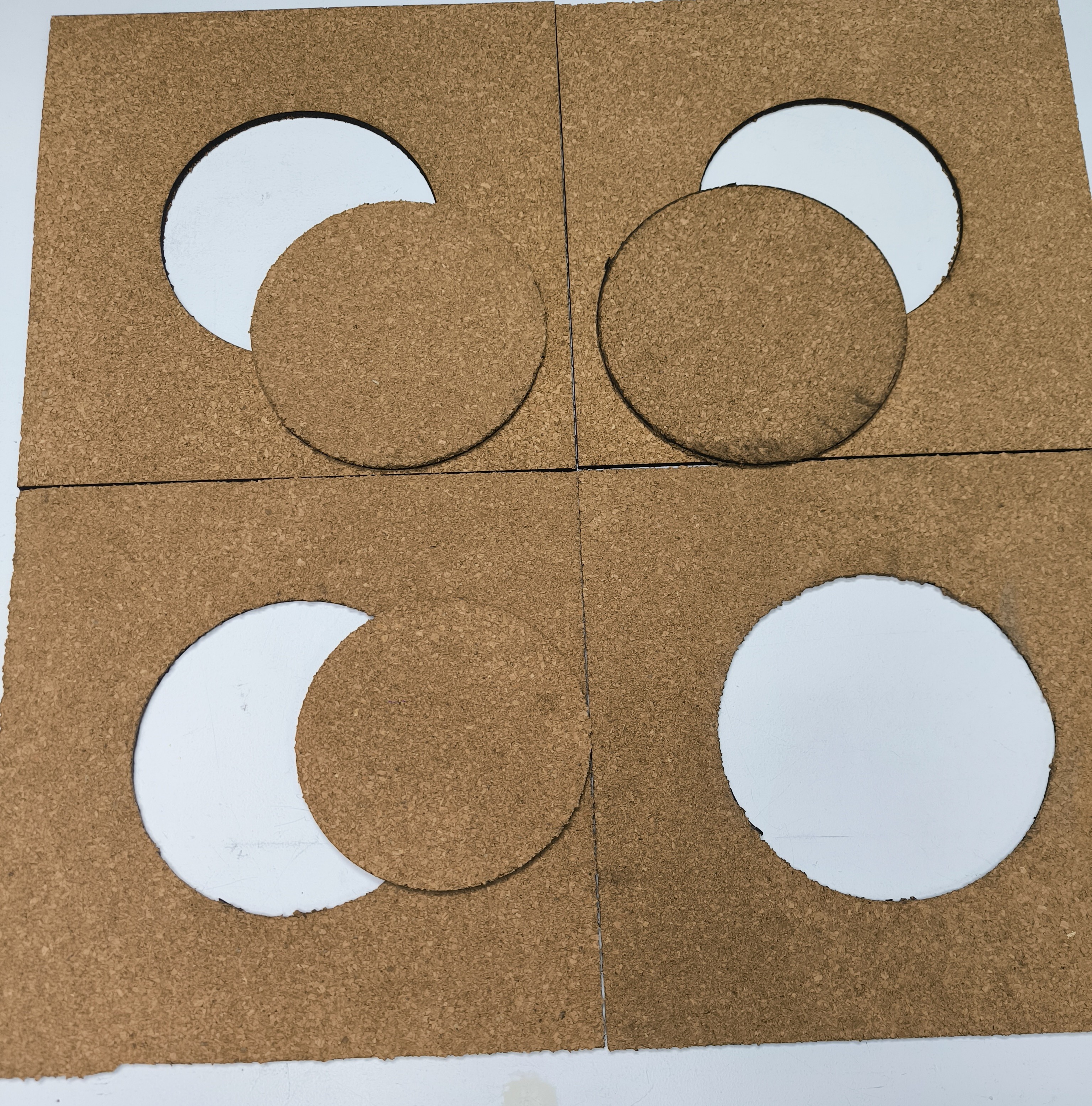
In order to provide a good level of insulation to the pan and prevent uncesseary amibent air cooling, I decided to Laser cut out different diameters corresponding to the the first half of the pan. Each of my cork sheets were 6mm thick, so the idea was cutting different diameter circles to surround the pan at different heights.
The design was simple, 4 different diameter circles that were cut out using the Rayjet400, the rhino file is given below. Figure 2.23 show the different cut outs and the pan resting in position.
2.2.3 Electronics
The electronic design for this project is relatively simple. The idea is to track the temperature of the cooking surface before and after applying the sun concentrator and the food. To do this a ceramic thermistor is placed under the pan, wedged between the pan and the insulating cork floor panel.
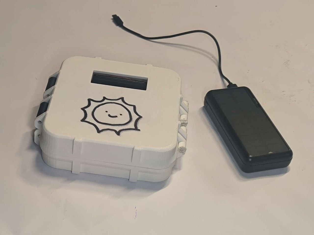
The resistance difference is transformed into a temperature reading which is shown on a RGB LCD screen, that is located in a rugged 3D printed case close to the cooker. For a more comphrensive recording and analysis of the temperature transient, an antenna hsa been added to the microcontroller (XIao ESP32S3) so that it can connect to the Arduino Cloud and record the temperature on there.
Since it is likely to be extremely hot when carrying out the experiment, being a sunny summer’s day in Barcelona, the Xiao and Arduino Cloud can inform a user sat in the shade that the cooking temperature has been reached via a message on the Arduino Cloud Dashboard.
The work can hence be broken down into 3 main components for the electronics :
- PCB Board (XIAO + Grove Connectors + Thermistors + RGB LCD Screen)
- Arduino Coding and Networking
- 3D printed rugged case
2.2.3.1 PCB BOARD + XIAO + Connection
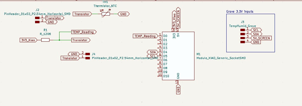
I decided that I was going to use a Xiao ESP32S3 with a thermistor as an input device and an RGB LCD Screen and a connection to the Arduino cloud as the output devices I designed the board to have :
- a 2 pin connector for the wire of the thermistor
- a removable Xiao ESP32S3 connector
- 3 3V3 Grove connectors (1 for the RGB LCD Screen and two spare)
- 1 5V Grove connector for any future updates.
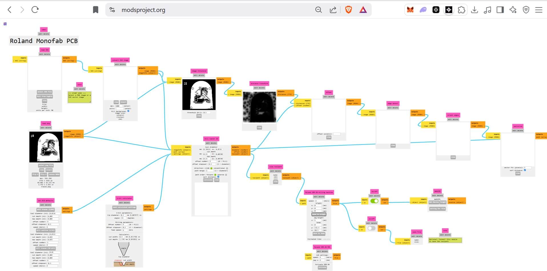
The KICAD design is given hereafter in elsol.zip along with the png files used in modsprojects and the .rml files (PCBSolarCookerMillingPNGrml.zip) used by the Roland milling machine to make the PCB Board. Figures 2.24 to 2.27 show the overview of each step.
- First, designing the schematic
- Second, designing the PCB board and aligning the traces efficiently
- Third exporting the pdf, loading it up in inkscape and separating the traces and holes layers and the outline.
- Using modsprojects.org to load the traces, holes and outline png files and select the correct endmill and maching settings for the ROLAND SRM20. This process is written in more detail in the Week 8 - Electronic Production homework.
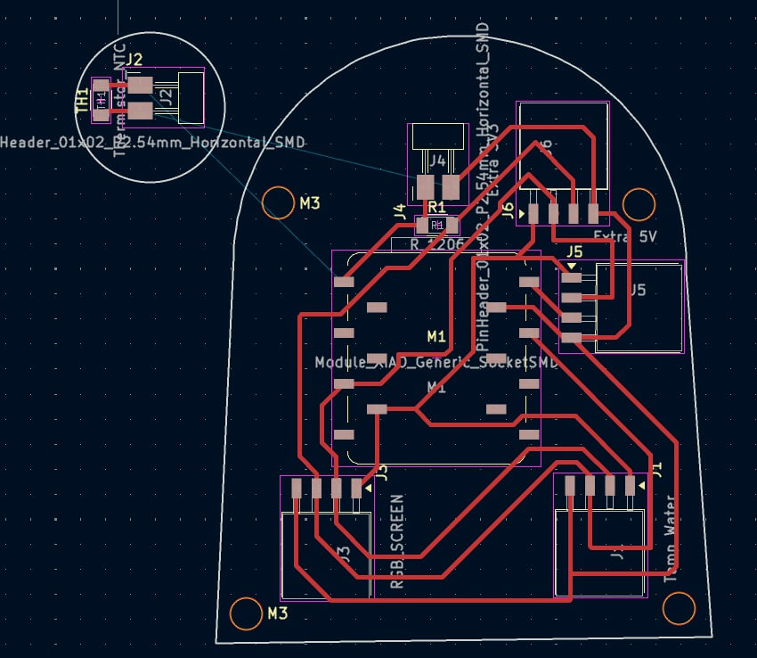

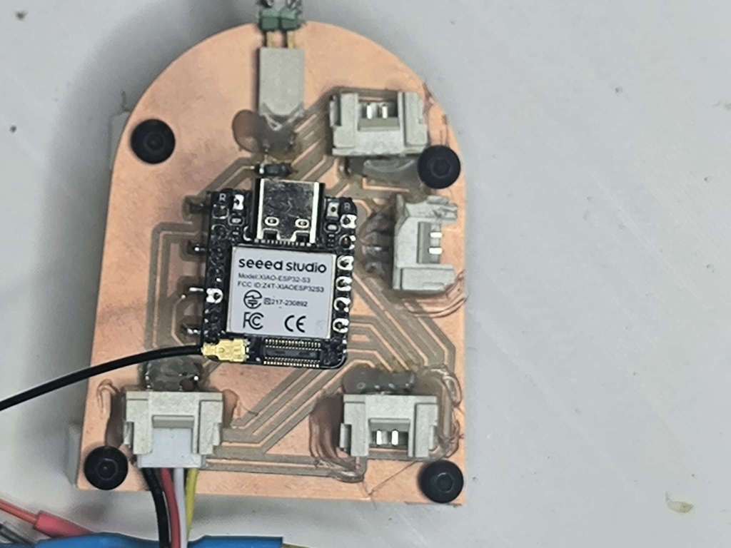
The resulting board is a nicely executed tidy design. I soldered the grove connectors, xiao connectors and the thermistor connectors to the board, and we are ready to do some coding!
2.2.3.2 Arduino Coding and Networking
2.2.3.2.1 Thermistor
The Xiao has one input (thermistor) and two outputs (RGB LCD Screen and Arduino Cloud Dashboard). My conversation with Google Gemini can be seen here.
The Xiao was coded using the Arduino Cloud app, the sketch and associated files to connect the XIao to the Cloud via wifi are given in the zip file below. The device key, wifi password and name of the wifi are defined in the arduino_secrets.h file, entering the respective values between the “”.
#define SECRET_DEVICE_KEY ""
#define SECRET_OPTIONAL_PASS ""
#define SECRET_SSID ""The temperature is calculated using an approximation of the Steinhart-Hart Equation
T = Temperature,
T_0 = Reference Temperature (273.15+25)
Beta = 3950 corresponding to a typical value for an NTC thermistor
R = Resistance changes with temperature, exploited to get a temperature reading
R_0 = 10000 K resistor used in the circuit
// Function to read thermistor and calculate currentTemperatureCelsius
void readTemperature() {
  float totalAdcValue = 0;
  for (int i = 0; i < NUM_SAMPLES; i++) {
    totalAdcValue += analogRead(THERMISTOR_PIN); // Read the analog value
    delay(SAMPLE_DELAY_MS); // Short delay for ADC stability between samples
  }
  float averageAdcValue = totalAdcValue / NUM_SAMPLES; // Calculate the average

  // --- Convert ADC value to Voltage ---
  float vOut = (averageAdcValue / ADC_MAX) * V_IN;

  // --- Calculate Thermistor Resistance ---
  float thermistorResistance;
  // Use voltage divider formula: R_therm = R_series * (V_out / (V_in - V_out))
  // Protect against division by zero or near-zero in the voltage divider calculation
  if (abs(V_IN - vOut) < 1e-6) { // V_out is effectively V_IN (open circuit or very cold thermistor)
      thermistorResistance = 1e9; // Assign a very large number
  } else if (vOut < 1e-6) { // V_out is effectively 0 (short circuit or very hot thermistor)
      thermistorResistance = 1e-9; // Assign a very small number (near zero)
  } else {
      thermistorResistance = SERIES_RESISTOR * (vOut / (V_IN - vOut));
  }

  // --- Calculate Temperature using Steinhart-Hart Equation ---
  // Equation: 1/T = 1/T0 + (1/Beta) * ln(R/R0)
  // Where T is temperature in Kelvin, T0 is nominal temperature in Kelvin,
  // R is thermistor resistance, R0 is nominal resistance, Beta is B_COEFFICIENT.
  if (thermistorResistance > 0 && NOMINAL_RESISTANCE > 0 && B_COEFFICIENT > 0) {
    float t0_kelvin = NOMINAL_TEMPERATURE + 273.15; // Convert nominal temp to Kelvin
    float steinhart_val = thermistorResistance / NOMINAL_RESISTANCE;

    if (steinhart_val > 0) { // Ensure log argument is positive for log()
      steinhart_val = log(steinhart_val); // Calculate natural logarithm
      steinhart_val /= B_COEFFICIENT; // Divide by Beta coefficient
      steinhart_val += (1.0 / t0_kelvin); // Add reciprocal of nominal temperature in Kelvin

      if (abs(steinhart_val) > 1e-9) { // Avoid division by zero or near-zero
        currentTemperatureCelsius = (1.0 / steinhart_val) - 273.15; // Calculate reciprocal and convert back to Celsius
      } else {
        currentTemperatureCelsius = -998.0; // Error in calculation (reciprocal very large)
      }
    } else {
      currentTemperatureCelsius = -997.0; // Error with resistance ratio (zero or negative)
    }
  } else {
    currentTemperatureCelsius = -999.0; // Error with constants or initial resistance check
  }
2.2.3.2.2 RGB LCD Screen
I selected an RGB LCD Screen from the Lab that can connect via I2C. It uses the DFRobot_RGBLCD1602.h library.
The code initialises the LCD backlight colour, and changes colour based on the temperature. Changing the back colour is a little obsolete but it is included anyway.
// Function to update the LCD display
void displayTemperatureOnLCD() {
  lcd.clear(); // Clear the entire LCD screen
  lcd.setCursor(0, 0); // Set cursor to column 0, row 0
  lcd.print("Oven Temp:"); // Print a label on the first line

  // Display Cloud connection status indicator at the top right of the LCD
  lcd.setCursor(15,0); // Set cursor to column 15, row 0 (far right)
  if (ArduinoCloud.connected()) {
      lcd.print("*"); // Asterisk indicates connected to Arduino Cloud
  } else {
      lcd.print("X"); // 'X' indicates not connected to Arduino Cloud
  }

  lcd.setCursor(0, 1); // Set cursor to column 0, row 1 for temperature display

  // Check if the current temperature reading is plausible (above approx. absolute zero)
  if (currentTemperatureCelsius > -270.0) {
    char tempStrC[7]; // Character array to hold the formatted temperature string
    // Convert the float temperature to a string: width 5, 1 decimal place (e.g., " 25.5", "103.2")
    dtostrf(currentTemperatureCelsius, 5, 1, tempStrC);

    lcd.print(tempStrC); // Print the formatted temperature string
    lcd.print((char)223); // Print the degree symbol °
    lcd.print("C"); // Print the Celsius unit indicator

    // Dynamically change LCD backlight color based on temperature relative to cookingThreshold
    // Thresholds are adjusted to make sense for typical cooking/oven temperatures.
    if (currentTemperatureCelsius < cookingThreshold * 0.6 && cookingThreshold > 50) {
      // Significantly below a reasonable threshold: Blue
      lcd.setPWM(lcd.REG_BLUE, 255); lcd.setPWM(lcd.REG_GREEN, 0); lcd.setPWM(lcd.REG_RED, 0);
    } else if (currentTemperatureCelsius < cookingThreshold - 10 && cookingThreshold > 20) {
      // Warming up, but still more than 10C below a reasonable threshold: Yellowish/Greenish
      lcd.setPWM(lcd.REG_GREEN, 200); lcd.setPWM(lcd.REG_BLUE, 50); lcd.setPWM(lcd.REG_RED, 150);
    } else if (currentTemperatureCelsius >= cookingThreshold) {
      // At or above threshold: Red
      lcd.setPWM(lcd.REG_RED, 255); lcd.setPWM(lcd.REG_GREEN, 0); lcd.setPWM(lcd.REG_BLUE, 0);
    } else {
      // Approaching threshold or if threshold is low: Orange/Yellow (or default Blue if threshold is very low)
      if (cookingThreshold > 20) {
           lcd.setPWM(lcd.REG_RED, 200); lcd.setPWM(lcd.REG_GREEN, 100); lcd.setPWM(lcd.REG_BLUE, 0);
      } else {
           lcd.setPWM(lcd.REG_BLUE, 255); lcd.setPWM(lcd.REG_GREEN, 0); lcd.setPWM(lcd.REG_RED, 0);
      }
    }
  } else {
    // Display "Sensor Err" if temperature reading is implausible
    lcd.print("Sensor Err");
    // Set backlight to Red to indicate an error
    lcd.setPWM(lcd.REG_RED, 255); lcd.setPWM(lcd.REG_GREEN, 0); lcd.setPWM(lcd.REG_BLUE, 0);
  }
}
2.2.3.2.2 Connecting to the Arduino.cc
The WiFi.h and WiFiClientSecrure.h along with the thingProperties.h (detailing the wifi connection) libraries allow the Xiao to connect to Arduino.cc via the wifi (ensure that the antenna is connected to the Xiao!). An extract of the code is given here, with annotations (thank you Gemini) to help explain in great detail each part of the code.
// Initialize Cloud Variables and Connection properties (defined in thingProperties.h)
// This function is auto-generated in thingProperties.h. It typically:
// - Calls ArduinoCloud.setThingId(DEVICE_LOGIN_NAME); (or similar based on auth method)
// - Calls ArduinoCloud.addProperty(local_var, cloud_var_permission); for each cloud variable
//   (e.g., ArduinoCloud.addProperty(temperatureCelsius, READWRITE);)
// - Registers callbacks for writable properties (e.g., ArduinoCloud.addProperty(cookingThreshold, READWRITE, ON_CHANGE, onCookingThresholdChange);)
initProperties();

/*
   The following function allows you to obtain more information
   related to the state of network and IoT Cloud connection and errors
   the higher number the more granular information you’ll get.
   The default is 0 (only errors). Maximum is 4.
   Set to 2 for helpful debug messages during network/cloud connection.
*/
setDebugMessageLevel(2); // Set verbosity of debug messages from the Cloud library
ArduinoCloud.printDebugInfo(); // Print initial Cloud library debug information

// --- DEBUGGING WIFI/CLOUD CONNECTION VARIABLES (Should match arduino_secrets.h and Thing Setup) ---
// (This block prints SSID, partial PASS, and partial DEVICE_KEY for debugging connection issues)
Serial.println("--- WiFi and Cloud Connection Debug ---");
Serial.print("Value of SSID variable: ");
Serial.println(SSID); // SSID is usually defined in thingProperties.h (from arduino_secrets.h)

Serial.print("Value of PASS variable (CAUTION - PASSWORD): ");
if (strlen(PASS) > 0) { // PASS is usually defined in thingProperties.h (from arduino_secrets.h)
    for(int i = 0; i < min((int)strlen(PASS), 8); ++i) Serial.print(PASS[i]);
    Serial.println("...");
} else {
    Serial.println("Password is empty!");
}

// DEVICE_KEY is defined in thingProperties.h (from SECRET_DEVICE_KEY in arduino_secrets.h if using device key auth)
Serial.print("Value of DEVICE_KEY variable (first few chars): ");
if (strlen(DEVICE_KEY) > 0) {
  for(int i = 0; i < min((int)strlen(DEVICE_KEY), 8); ++i) Serial.print(DEVICE_KEY[i]);
  Serial.println("...");
} else {
  Serial.println("Key is empty!");
}
 Serial.println("---------------------------------------");
 // --- END DEBUGGING ---

// Connect to Arduino IoT Cloud
// This uses the WiFiConnectionHandler object (e.g., ArduinoIoTPreferredConnection)
// initialized with SSID and PASS from thingProperties.h.
// This call is BLOCKING and will wait until connection is established or a timeout occurs.
Serial.println("Attempting to connect to Arduino IoT Cloud...");
ArduinoCloud.begin(ArduinoIoTPreferredConnection); // ArduinoIoTPreferredConnection is your connection handler object

// After attempting connection, check and report the status
if (ArduinoCloud.connected()) {
  Serial.println("Connected to Arduino IoT Cloud!");
  // NOTE: ArduinoCloud.syncState() was commented out in your original code as potentially
  // not available or needed with current library versions for basic variable sync on connect.
  // Cloud variables with READWRITE permission usually sync automatically upon connection and change.
} else {
  Serial.println("Failed to connect to Arduino IoT Cloud.");
  Serial.print("Final WiFi Status Code: ");
  Serial.println(WiFi.status()); // Print WiFi status code for debugging
  Serial.println("Check credentials in arduino_secrets.h / Thing setup.");
  Serial.println("Check network (2.4GHz, signal).");
}

// Initialize or verify local values linked to Cloud variables after connection attempt
if (cookingThreshold < -50.0 || cookingThreshold > 300.0) {
  Serial.println("Cooking threshold seems uninitialized or out of range after sync, setting fallback default.");
  cookingThreshold = 25.0; // Apply a local fallback default
}
 Serial.print("Initial/Synced cookingThreshold: "); Serial.println(cookingThreshold);
 Serial.print("Initial/Synced alertSentFlag: "); Serial.println(alertSentFlag);
The result is an interactive dashboard on Arduino.cc where you can modify the cooking threshold, the temperature value at which a message is sent to notify the user that the cooking temperature has been attained, 80°C in this case. In Figure 2.27 notice the messages:
- -113.6 °C is where there was an error with the pins defined for the resistor, 0°C was when the threshold temperature was changed by error, and 80°C was when the experiment started. The transient is misleading as the temperature actually attained 102°C.
2.2.3.3 Rugged Case
I spent a day trying to design my own case by extruding a child’s drawing of the sun in Blender but I decided that it was taking too much time with the deadline fast approaching. So I chose to take a rugged case design from printables.com and modify it to have supports for PCB board design and the RGB LCD Screen.
The design I copied, the modified design blender file the two stls and the sliced latch file is given below.
https://www.printables.com/model/750780-ifixit-mako-driver-kit-rugged-box
The case was 3D printed with the Bambu Carbon X1, and the input and output devices were screwed in place. I forgot to make space for the cable between the portable battery and the Xiao and also the thermistor cable. It was enough to keep the case slightly open during the experiment, so I decided not to melt a hole into the side of the rugged case. The case can be seen in Figure 2.28 below.
2.3 Solar Cooking Experiment
Now it is finally time to test if the setup can attain temperatures appropriate for cooking. First I would like to point out the limitations:
- Solar Concentrator lacks precision and only loosely approximates the parabola designed in CPC creation.
- The exit aperture of 39 cm is much larger than the 28 cm pan. The pan handle also means that the concentrator is tilted on the handle, therefore there is some loss of light reflected and also some space for the heat to escape that is not isolated.
The setup for the experiment was that of a camp fire, the pan is placed in the cork insulation on the floor The concentrator is supported on the ground with three bag of rocks, and directed to the sun manually. The rugged case was placed next to the cooking plate, with the thermistor wedged between the floor plate and the bottom of the cooking pan. The setup is shown in Figure 2.29 below and some of the experiment can be seen in the final presentation video here.
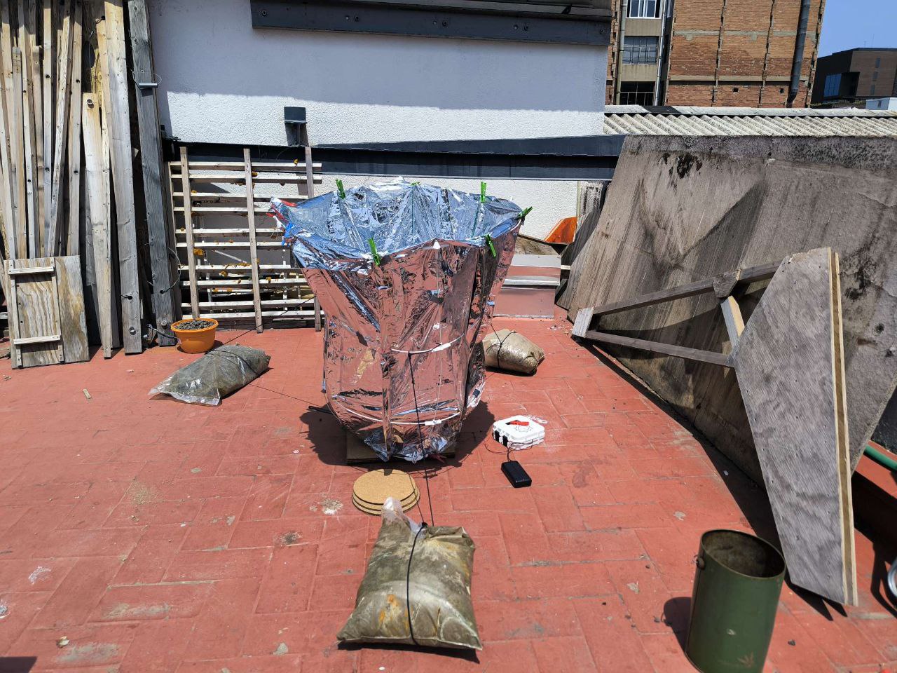
Figure 2.30 below shows how the pan heated up directly in sun without the concentrator. The temperature rounded off around 62°C.
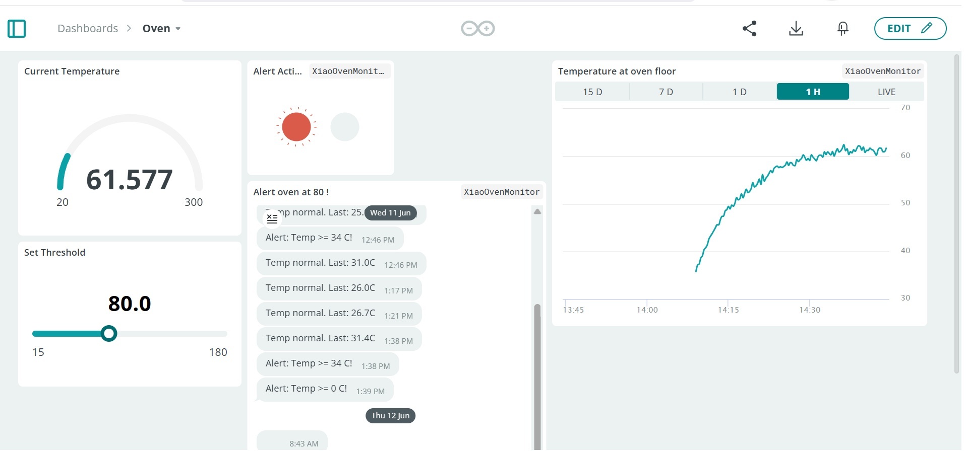
Once the sun concentrator was added the the temperature increased steadily to 100°C and topped out at 102°C. Butter was then added, with the temperature dropping to 85°C. The temperature started to rise again, and I added the organic eggs. The temperature dropped to 70°C, and then cooked slowly for an hour. For precaution I waited until the pan had retained 75°C and the eggs looked cooked. This transient can be seen in Figure 2.31 below.
Slices of truffles were added, and the eggs were enjoyed with rocket and capers. Yummy. Once again the whole process can be seen in the final video presentation here.
2.4 Experiment Outcomes
2.4.1 Discussion
The solar concentrator has a significant impact on temperature. Further improvements to the concentrator will only improve the heat transfer, better insulation and a more appropriately sized cooking surface will increase the cooking temperatures.
I was able to cook tasty eggs, possibly the tastiest eggs will ever eat ! I was however hoping to attain temperatures closer to 180°C. Perhaps after some improvements have been made.
I hope to develop this project further, as it has the potential, to generate suffucient cooking temperatures for a variety of dishes. The design can be low-tech and inexpensive and used in many countries where there is sufficient sunshine, especially between the tropics. I will of course take some time to work on other projects, in the hope that I will have fresh ideas at a later date.
I hope other people can be inspired by this project to use solar concentrators to prepare meals.
2.4.2 Possible Improvement
A number of improvements can be implemented to improve cooking temperatures and make it more practical for home or community cooking.
- A more robust and precise solar concentrator, experimenting with more permanent structure, using origami and metal sheets, using an inflatable membrane, sticking ALUPET to the surface with an adhesive and post treating it to have a better reflectivity.
- I truncated the CPC design at 1m, it would be interesting to see the difference with a full height CPC > 2m. Also 16° acceptance half angle could possibly be more appropriate.
- A pully system could be put in place to move the 3 lengths of rope so that the concentrator is always directed at the sun.
- Improving the UI, and experimenting with different foods to get a cookbook of different cooking times.
Warning : Cooking temperatures need to be high enough to not propagate unhealthy bacteria. Food should be cooked to a temperature of at least 145°F (63°C) and preferably 165°F (74°C).https://www.fsis.usda.gov/food-safety/safe-food-handling-and-preparation/food-safety-basics/danger-zone-40f-140f#:~:text=If the temperature is above,or below 40 °F.
2.5 Bill of materials