02— Computer Aided Design
Week 2: Computer Aided Design
Assignment
Deliverable(s)
- Model (raster, vector, 2D, 3D, render, animate, simulate, ...) a possible final project, compress your images and videos, and post it on your class page
Learning Outcome
- Evaluate and select 2D and 3D software
- Demonstrate and describe processes used in modeling with 2D and 3D software
Core Questions
- Modeled experimental objects/part of a possible project in 2D and 3D software
- Shown how you did it with words/images/screenshots
- Included your original design files
00 — Setup + Grid Search Method
Before We Begin
I chose to model the Lego brick because it allowed me to get a sense of exactly how Fusion, Blender, and Rhino varied in their workflows. Specifically, all three programs handle array and layer management very differently. Rhino’s treatment of array/object copying was definitely my favorite—though that is just about the only thing I like about Rhinos UI.
My final project was done in Fusion. Going forward probably a hybrid modeling approach is where I will land with some primary software, likely Fusion pulling all of the files together. I still don’t really understand how to place object properly in either Rhino or Blender with accuracy so I need to figure this out before I know how to really model something using a normal workflow. With both I think I need to follow tutorials that are more about modeling a specific object because I barely understand the mesh based workflow.
Ultimately, I think the most valuable lesson I learned in the process of trying to speed run the basics of modeling in Rhino and Blender was that there is definitely a place for a soft modeling in my current CAD workflow. I think the knowledge will make me far better in 3D too because I am starting to recognize all of the times in the past where I was simply using the wrong tool for the job or relying to much on habit or what was familiar when modeling when some more explorations or a different overall approach might have been more relevant.
Some Philosophy: The What and Why of Grid Searching
I have identified an approach I like taking when I am overwhelmed with the shear amount of potential options and paths to solving a problem. This approach I refer to as a grid search. This is also an approach I use when trouble shooting hardware or when I have just started learning a new skill. The idea first came to me from an experience I had 10 years ago when I was lost on a two week group camping trip deep in a forest in the High Seirra’s in California. It is not revolutionary or even particularly clever, but it is a kind of blunt force tool I keep on hand when needed.
It was partway through the trip and we had just began the section where we camp 48 hours alone. After just settling in to my solo camp spot the granola I had been eating all week began to catch up with me and I immediately had to run to a spot far away from my camp… a little too far. I went in a random direction towards the river without thinking about where I was going and then immediately got a bloody nose from dehydration. So all of the sudden I was lost and could not remember where my camp site was.
What I did know though was that I only ran for about 5 min. This meant I was something like .4km from my campsite. Similarly I knew that I had run to a stream so when facing the stream I knew it was behind me. With this limited, but helpful information I roamed for an hour and a half randomly and often to the same locations not able to find my campsite. As it began to get dark it dawned on me… the one way I could guarantee that I found my campsite was to search in a grid—it would be slow—might even be slower, but it would guarantee that I would find my campsite. In this scenario what I needed was a guarantee. So all I did was stupidly walked laps back and forth at an increment of about 10 meters and I found my campsite in about an hour.
How does this apply to learning software? The way I apply this kind of approach with learning something like software is to first scan for resources that seem thorough, relevant and concise. When I am alone and not super pressed for time I actually prefer learning from books. Instructional books tend to provide reliable and concise information because there is more effort put into their editing. Similarly, books geared towards teenagers or even kids tend to avoid needlessly complex descriptions or jargon. On a few occasions I have simply read a book like this cover to cover very slowly and just taken an extreme amount of notes almost like I was attempting to rewrite a shorter version of the book. I have only managed to do this for a hand full of books and it takes me an embarrassingly long time like several months. The times I have done it though it has never been a waste of time…yet. Ultimately the more general lesson for me as my temperament is actually more impatient is that being thorough an methodical is often more efficient. Anyways, that blunt force tool is there when I need it.
Style guide for key commands
LMBLeft Mouse Button
RMBRight Mouse Button
MMBMiddle Mouse Button
MWMouse Wheel
cmd
ctrl
alt
shift
+to denote keystrokes pressed sequentially
s , w, e etc.denote any single letter key presses
menu itemdenote a level 1 menu or button item in a primary active workspace
menu item→ menu item 2would represent a multi level button or menu level selection
menu item → item a / item b / item cwould denote relevant menu options to choose from
01— Image and Video Compression
Capturing Images / Gifs / Videos
Cleanshot
- Cleanshot is a paid app that is absolutely worth it on Mac OS and is a critical part of my Fab academy workflow. It lets me flexibly capture pictures gifs and videos and modify them in various ways prior to saving. Just get it and use it if you are on mac OS. Gifox is another option specifically for gifs if you need more gif specific settings.
Compressing Images
Image Magick command line approach
- First I Installed Imagemagick through terminal (MacOS w/ prior Homebrew installation)
brew install imagemagick
- Then I queried chat GPT to generate a command line prompt to compress images that existed in the working directory. This way my workflow is to simply place all of the screenshots and photos I need into a folder right click the folder and click
open in terminalthen paste my script for processing the photos into the terminal window. After experimentation with image quality this is the script I now use for photo processing.magick mogrify -format jpg -quality 65 -strip -resize 800x -- *.jpg 2>/dev/null && ls -v -- *.jpg 2>/dev/null | awk '{printf "mv \"%s\" \”about_me_%03d.jpg\"\n", $0, NR}' | bash
Preview (MAC)
- For single photos I just open them in preview click
sizein sub menu and set my width dimension to 800px
- I then export the file as a
.jpgwith a quality of 30 / 50% using a calculated file size of less than about 90KB
Video Compression
ffmpeg command line video compression
- First I Installed ffmpeg through terminal (MacOS w/ prior Homebrew installation)
brew install ffmpeg
- Then I queried chat GPT to create a command line prompt to compress the videos. As in the photos I place them in a folder prior to running the script and confirm they are all .mov. Something to note is this script only works for .mov (case senstive) this is not a problem because this is the file format I am primarily using.
ffmpeg -i "$file" -vf "scale=480:-1" -c:v libx264 -preset fast -crf 28 -c:a aac -b:a 128k "${file%.mov}.mp4”
Embedding
Conventional HTML workflow
- Originally I was using standard HTML embedding for both photo and video.
Photo
<img src="images/sample-image.jpg" alt="Sample Image" width="640" height="360">Video
<video width="640" height="360" controls>
<source src="videos/sample-video.mp4" type="video/mp4">
Your browser does not support the video tag.
</video>
iFrame Workflow
- I now simply place all of my assets including project files into notion and export the whole thing as
HTML. This provides the HTML and all assets in an organized folder.
- Folder is moved into website repository
- Folder name and HTML page inside folder are renamed based on my convention [notion_week#]
- Notion page is then placed into appropriate page on website by using an iFrame element in my IDE (Cursor).
	<iframe
				src="./notion_week_3/notion_week_3.html"
				frameborder="0"
				scrolling="no"
				onload="resizeIframe(this)"
				id="notionFrame"
	></iframe>
02 —Basics of Blender
Core UI Flow
List item summary: I am still tweaking how I approach learning software in general. For working with blender I did the obvious and just tried to get an overview of the main modeling workspace keeping a kind of mental note of its idiosyncratic with other CAD platforms I have experience with. I sorted this out through reviewing my notes from the class session (mostly just shortcuts) and watching and copying Blender Tutorial for Complete Beginners - Part 1 very slowly. In fact this is something I have noticed in the past with software tutorials. In this case a 20 min tutorial took me 6 to 8 times that set video length to follow along play with the ideas and write notes… so 20 min ~ 3 hrs in this case.
- Object vs Edit Mode
tabswitches between them
object mode→ object mode- For things related to positioning and transforming discrete entities.
object mode→ edit modeselect modewhen in edge face mode1vertices selection mode
2edges selection mode
3face selection mode
- Viewport render modes
- Use display render preview when you want a preview of shadows
- Adding Objects
shift + aopens add menu- An object can then be selected and an editing pane can be opened on the bottom left to toggle a contextual menu for that object.
- Modifiers
- Very deep, but many modifiers can be added no destructivel to object or object groups(?) in your collection.
- Applying Transforms
ctrl avery important to apply changes like scale after they are made. Opens a menu and allow you to apply transforms this needs to be done after an important change like scaling
- Shading in viewport to great smoothing or reveal mesh
RMB + shade flat / shade smooth / autosmooth
Personalizations
- Changing core interface settings: monitor default scale, orbit, pan and zoom commands to mimic Autodesk Fusion, Setting default units.
- Monitor default scale
- Orbit pan and zoom like fusion
- Setting default units
scene → units → mm
scene → units → unit scale [0.001]
viewport overlays → scale [0.001]
view → (clip) end [10,00]
select camera → camera properties → (clip) end [10,000]
file → defaults → save startup file
menu→ Render imageto render image- Renders will occur from the point of view of the camera
- Outliner
- Essentially what is more commonly reffered to as a layers panel found in other software. All object types in your scene are listed here with the ability to add ‘collections’ (folders).
- Render vs viewport
- Many feature can be enabled or disabled for the render / viewport. The selected render engine only is applied when
‘viewport shading is selected’otherwise the default light weight renderer is used
- Many feature can be enabled or disabled for the render / viewport. The selected render engine only is applied when
Essential Key Commands
List item summary: Clearly Blender is idosyncratic in its exstensive use of key commands. From prior experience I know its better to just rip the Band-Aid off early and just and start memorizing the really core key commands through playing in the software.
g + x, y or z ’g’ initiates a grabbing mode ‘x’ ‘y’ ‘z’ lock the transpose direction
s + x, y or z sets scaling mode and ‘x’ ‘y’ ‘z’ note what you are scaling
r + x, y or z sets rotation mode and ‘x’ ‘y’ ‘z’ across which planes you are rotating
a select all objects in a scene
n opens property menu
shift + s full rotary menu opens
g + b vertice selection mode
shift + z wireframe mode
x delete
right click if you want to cancel out of a move mid move
g + MMB allows you to snap to an axis during move
click ‘camera’ moves camera positition
f12 quick render
shift + tab enable disable snapping
shift + c to move cursor to central origin
ctrl + 1 subdivision modifier
~ view select wheel
w selection tool
Detail camera adjustment
→camera icon + → camera object ‘g’ free pan camera from camera pov
→camera icon + → camera object g + r free pan camera from camera pov
→camera icon + → camera object g + MMB zoom from camera perspective
Working Blender Tutorial from Blender Guru
List item summary: With
shift + n → Insert TorousTweak polygon count to a low value with reasonable fidelity to give you the below. Lower poly gives you faster load times and polycount can be increased later.
- Set shading to
right click → shade smooththis will hide the low poly look.
- Click on modifiers
generate → subdivision surfacesthis is a way to non destructively subdivide faces to create a higher polygon surface and thus greater object fidelity. This is why the initial polygon count does not need to be super high.
- Switch to
→edit modethen1then select vertice→ proportional editingthengthen adjust withMWto shrink or enlarge. Basically you are trying to just make the donut look more organic.
- Edge select donut edge vertices in edit mode.
ctrl + LMBthen usesto flatten donut edge vertices.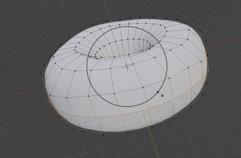
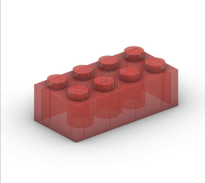
Making The Lego
- Doing this straight off the dome… no tutorial. Switch to modeling workspace… fuck just found this.
- Create the rectolinear envelope for the Lego piece - without the lego stud height. Make your cube in origin center → obviously… (I typcally use workflows based around origin center as they seem to be faster to build) use technical drawing dimensions to define set your length width and height of the envelope. Do this by pressing
nand inputing dimensions in relevant fields. USEctrl aand applyall transforms.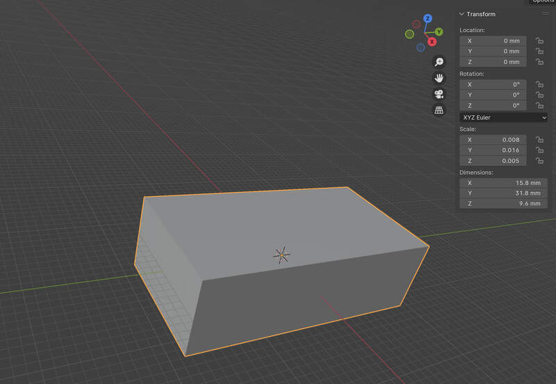
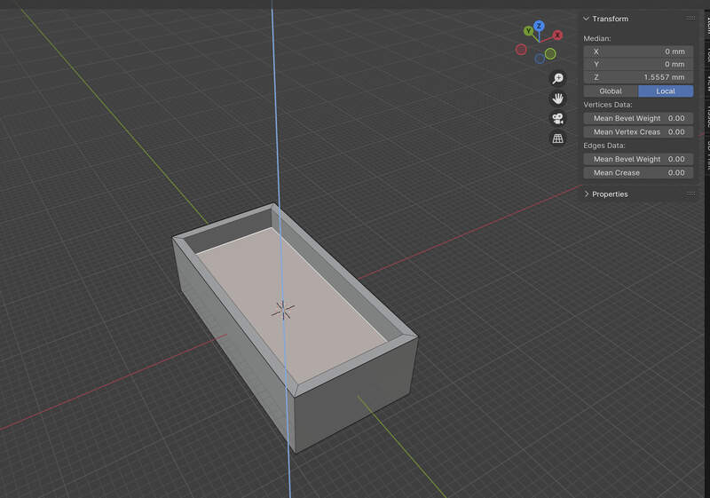
- Select the bottom face and create an offset with
inset facetool based on technical drawing offset [1.2].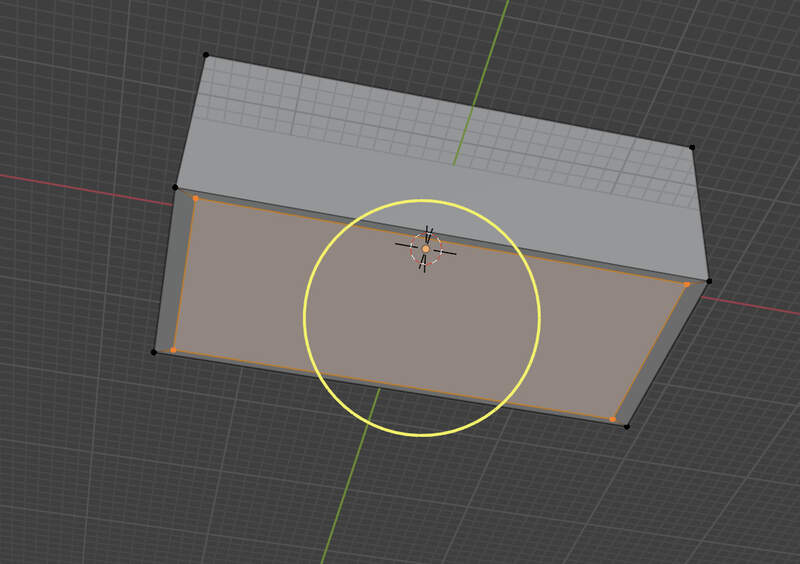
- Extrude face internal to specification
- Create and dimension cylinder
gmove to lego cornercmd + ato apply tranformations. Move up so it is flush with face manually move to position in the properties paneln.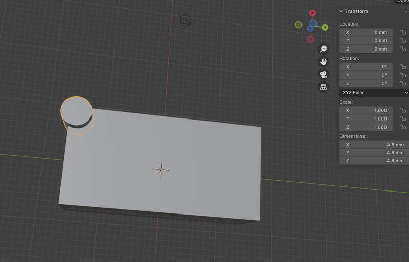
- Add array to cylinder object select
constant offsetset offset to [8] as its the distance between object centers. Add another array modifier in the object set the Y distance to [-8]. Apply changes of modifiers so they are ‘commited’ to the mode. This fixed an issue I had that was creating a weird profile when joining elements.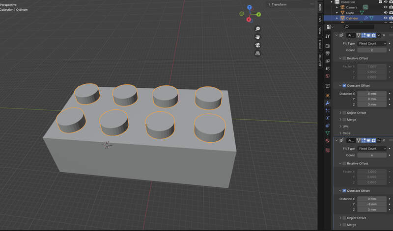
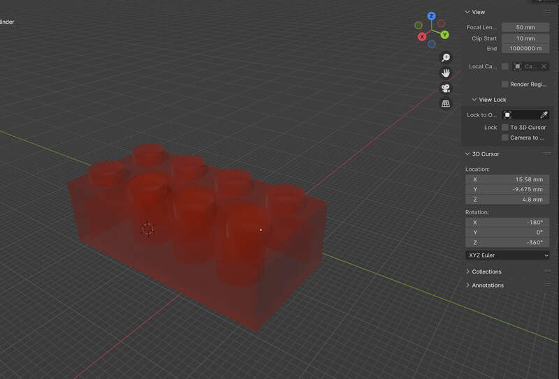
- Create cylinder copy cylinder insitu resize second cylinder for boolean cut operation. Perform boolean cut operation through boolean generator set to difference. Apply generator.
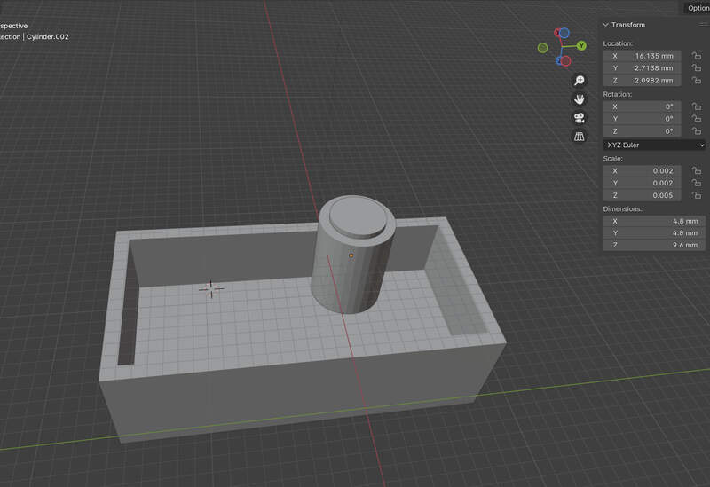
- Position cylinder apply array generator so they pattern at 8mm from center.
- Final result (just the primary body without the finer internal details)
— Citations
- Working through blender intro course section 02 https://youtu.be/tBpnKTAc5Eo?si=tYhqqYDMM42NLH4O
- Page on HackMD was consulted to for additional info in the program fundamentals section https://hackmd.io/ojtXMAVIQYyJJ86pPzzNpA
02—Basics of Rhino
Core UI Where and What
- Construction Plane (CPlane)
- Basically the primary 2D → 3D workflow appears to be similiar to hard surface modeling sketches workflow to programs like solidworks or Fusion.
- Viewport Area
- Top area
Front→ wireframe/shaded...allows you to select many viewport options.
- Bottom area
Perspective/Front/…are a selection of different custom view sets that can be saved.
- Top area
- Right Panel
- Layers Pane
- Appears to use a layer system that operates like blender however, not sure if it manages non destructive editing feature in this zone like blender does.
- Properties Pane
- Also pretty typical contextual object editing like blender.
- Layers Pane
- Left tools Panel
- Command Line Entry
- Rellies on command line heavily instead of key commands. Just start writing to automatically write in command line terminal.
- Help Tool Bar
- Always active in the right toolbar pane and is contextual.
Toolbar Resetto get back to original configuration
- Command Line Entry
- Bottom Pane
- Selection Filters
- Seems to be similiar to Fusion’s selection selection filter system through the cursor dropdown. Probably more relevant when working with meshes.
- World coordinates
- Working Unit
- OSnap
- Enables or disables the snapping options panel (left)
- CPlane
- Construction plane defines working plane
- Gumball (CPlane)
- Auto CPlane (Object)
- Record History
- Selection Filters
Core Concepts / Workflows
- Gumball
- Allows for transform,scaling, rotation
- Enable the
Gumbal(Cplane)- Scale from gumbal
shiftto scale uniformly
- Scale from gumbal
- Command line workflow
Movecommandshiftconstrains movementtablocks it inline with an axis
- Input values during object tranformation to set a context specific value.
- Copy by holding
option
- Gumball can be relocated
- Enable the
- Allows for transform,scaling, rotation
- CPlanes (construction planes)
- Sketches that work across all object kinds and can be used for things like creating surfaces, extruding, into 3D solids and object alignment. The do not utilize geometric constraints.
- SubD / Nurbs / Mesh
- SubD — A kind of fake mesh that seems to be better optimized for the design workflow in Rhino, but appears to utilize similiar design workflows to mesh based modeling.
- Mesh — Seems to make more sense to simply convert designs to mesh rather than designing in mesh. Mesh would be your final output for a context that utilizes mesh as a final input like 3D printing or game assets.
- Nurbs — Rhino’s implementation of a hard modeling work flow utilizing iso curves etc. By choosing
surfaceyou are using a nurbs workflow.
- Shrinkwrap
- Is very cool. Enables you to clean up a noisy or messy mesh file. Very useful when working from STLs
- Parametric workflow
- Is… a hot mess. It utilizes command line history which behaves differently than mac has some things that apply dynamically to objects and not others. Also utilizes like grasshopper that is managed as a second application through its node workflow.
- Grasshopper is fully parametric and rhino objects can be imported as static objects into
Essential Key Commands
Ctrl + J Join
BooleanUnion BooleanUnion
MergeSrf MergeSrf
MergeAllFaces MergeAllFaces
Weld Weld
JoinEdge JoinEdge
CollapseMeshFace CollapseMeshFace
Rebuild Rebuild
Grasshopper launches grasshopper
Learnings From Experimentation
shiftwhile drawing will deactivate orthographic snapping. You can also enablePlanarto permanently constrain the sketch to a single working plane.
- Active layer have a check mark in them and the color will denote the sketch line color
- Rhino is actually a hybrid package for nurbs like objects and meshes, but primarily uses nurbs based modeling like other solid modeling CAD packages.
- Dual workflow
- Primitives (knurb + mesh) workflow
- You can model objects based on primitives seamingly like Blender. I am sure there are some non-destructive advantages to using this workflow utilizing knurbs based primitives.
- Sketch based workflow (polylines)
extrude crv→ selectpolyline→ clicksolidextrude your selected polyline into a… surface? check make sureAutoCPlaneis off!
Push Pullwork only on surfaces
- Primitives (knurb + mesh) workflow
Rhino Lego
Discoveries While Working
- Enable
endin snaping panel to snap to a point on a solid.
- Your drag oreintation will define your dimension ‘from’ point so you can skip use -values.
- Option command is very powerful as it allows you to set distances between copies by directly inputing a spacing value from original object origin to new objects orgin.
- Not having the z axis up is killing me…
viewport dropdown→topplan + enterfile->save as template
Design Steps
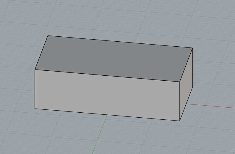
- Create center based rectangular solid from world orgin. Dimension to Lego envelop -stud height.
- Click bottom
Insetcommand set inset value → push pull
- Create CPlane alignment rectangle on edge as a construction sketch to position a dimensioned 3D cylinder solid.
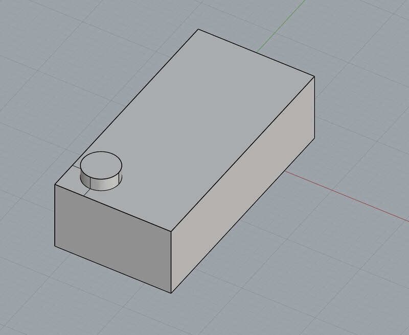
Optiondrage and input from center spacing value… repeat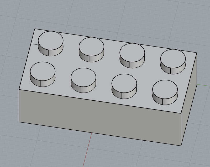
- Create cylinder dimensioned shelled internal cylinder by subtracting a smaller cylinder object through
boolean difference
- Position cylinder by
moveselect point and enter 0, 0 since it is modeled at origin.option + inputvalue approach to copy and place cylinders.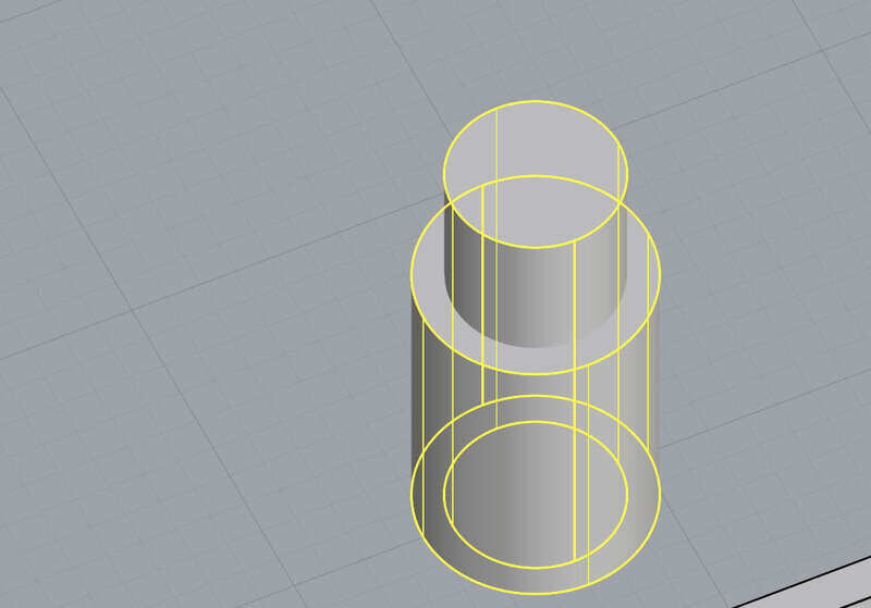
- Draw cylinder in alignment with the center of the stud at the cplane to later subtract from interior then use option move protocal then
groupobjects and useboolean differenceto create cutaways.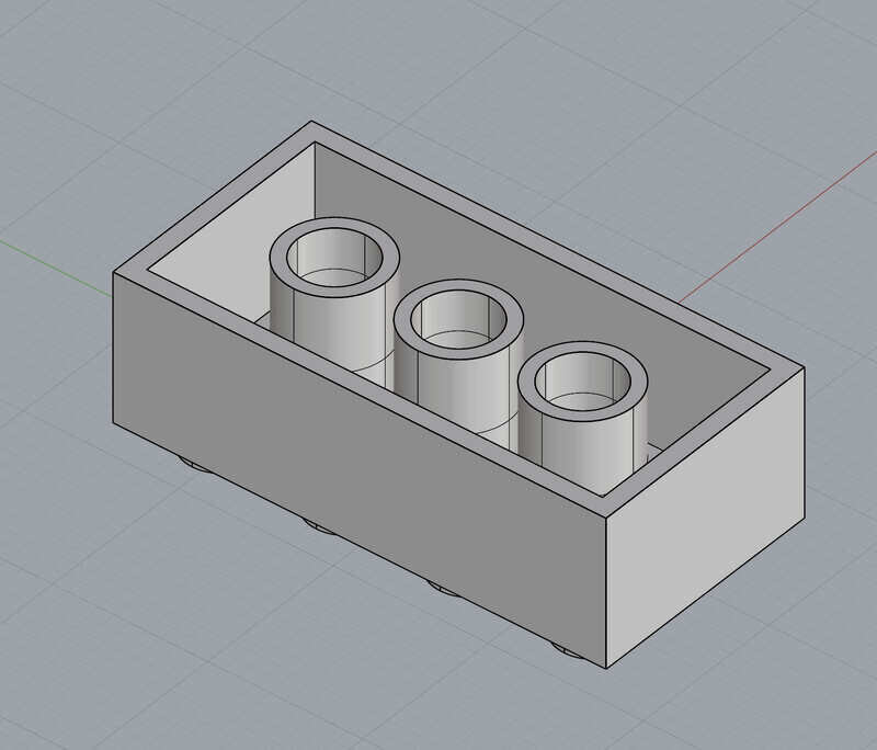
- Create rectangular solid at center that is slightly tall.
Push pullto sizeboolean joinpush pullto remove center of cylinder.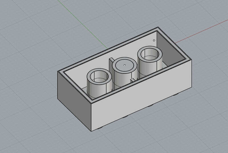
- Set cplan at bottom inset and save cplane as “lego” manually draw all nubs and
extrude crv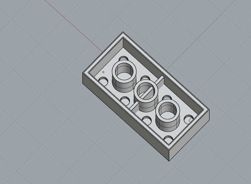
- Selection filter
select curvesdelete all curves
- Final Design
—Citations
- Dani Mateos—https://hackmd.io/@danimateos/S1WJmnO_Je
- The Rhino Essentials
- ChatGPT
- Chat GPT was utilized heavily to answer basic questions that were simply posed as they came to mind when experimenting with the UI. The questions followed the basic format of “what is the CPlane Function” “is Rhino parametric” “how do I reset the tool bar” etc.
03 Autodesk Fusion
A — New To me UI
- I did model the Lego in Fusion, but since I already have experience using fusion I didn’t feel I needed to document the process. That said the thing that was on my mind while making it was how well it was really modeled. I did not 3 subjects I have been avoiding in Fusion though that I would like to learn and that I think would improve my workflow.
Form
- Is Sub Division modeling like in Rhino… this is very interesting I have always been confused how this differs from mesh. Basically nurbs based mesh. These subdivided 3d forms can then be converted into solid object.
- Its a mode and does not represent a parametric operation with historicity. So it only show up as the a mesh body object that was created.
Surface Modeling
- Working with objects with no width. I can think of a few instances where I should have used a surface to cut or replace a face.
Rendering
- A basic understand of how to properly light and texture and object along with basic considerations around optimization.
—Citations
- Asking chat GPT what various functions in the software do i.e. “what does the function Form do in Autodesk Fusion” etc.
04 — 2D Software
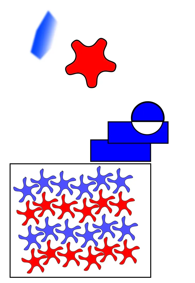
A — Inkscape!
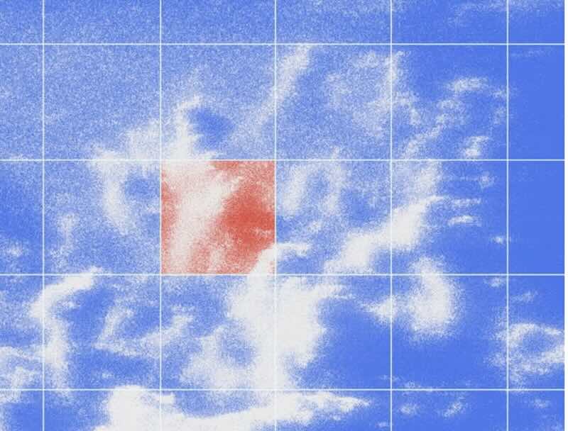
I didn’t get a chance to look deeply into inkscape I use illustrator as my defualt application, but do like inkscapes more focused feeling UI. Below is a sketch I created while simply clicking around and trying to find simililarities in Inkscapes vector workflow to Illustrator’s vector workflow.
- Rectangle tool was use to create rectangular profile. Line/ fill functions were identical to illustrator.
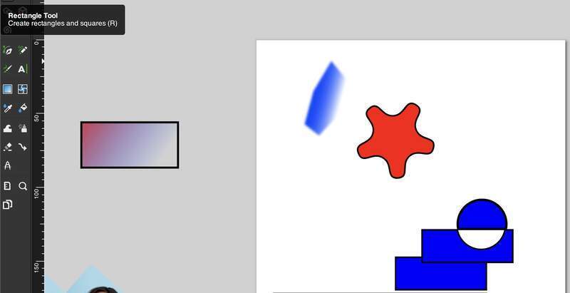
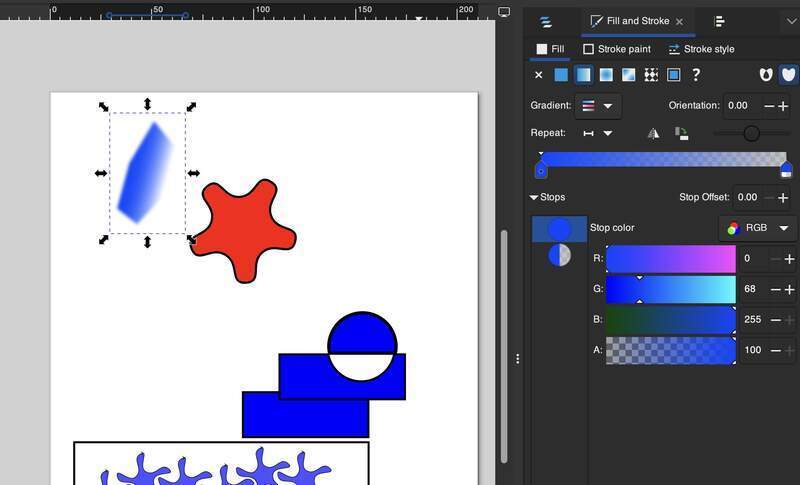
- Gradient was applied to this element by applying a gradient to the fill and feathering it.
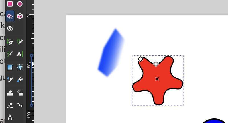
- This red shape was created by first creating a start and rounding over its edges.
- the white blue circle was created by divided the shape from the rectangle and deleting the resuling cut shape.
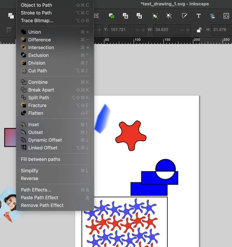
- The weird start thing are placed manually in a grid by copy paste and recoloring.
- Final— Composition is supposed to be a zig zag leading the eye from left to right.
B— Illustrator
I have decided that learning new software is less of a priority for me for FAB lab I like the software I use generally an I could be a lot better at using it. Especially Illustrator I use it as a blunt tool for layout and generating tool paths from 3D to 2D.
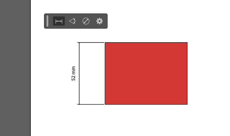
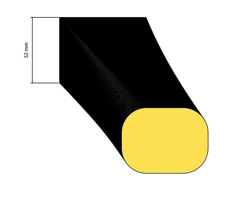
New tools to me
Dimension Tool— Select points and drag out aligned dimension
Blend tool — e
Object types— Pasted from Chat GPT prompt: “what are the main types of objects in illustrator in brief?”
1. Paths (Vector Shapes) – Made of anchor points and lines, used to create scalable shapes and outlines (e.g., lines, polygons, curves).
2. Compound Paths – Multiple paths combined to create complex shapes with transparent areas (e.g., cutouts).
3. Text Objects – Editable text that can be point text (single line) or area text (paragraphs).
4. Images (Raster Objects) – Placed bitmap images (e.g., JPG, PNG) that are not scalable without quality loss.
5. Symbols – Reusable vector graphics stored in the Symbols panel for consistency across designs.
6. Groups – Multiple objects grouped together to act as a single object for easier manipulation.
7. Artboards – Not an object but a workspace unit, each artboard represents a design layout or exportable area.
8. Layers – Organizational structure for managing and stacking objects in a design.
If you want, I can explain any of these in detail with examples. 😊
04— Raster Image Software
This is a bit of a funny one I have experience using Lightroom, but I have always used it in pretty basic ways. For the most part, I am doing simple color grading and photo editing with Apple’s ‘Photos’ and the IOS apps VSCO, West and Gliché. For exporting and file formatting I am now using Image Magick command line tool and I continue to use illustrator to bulk export and format raster images which is actually quite feature rich for basic photo editing even as a vector software.
Photoshop
I have some experience of photoshop but could use a little refresher.
- Similar setup screen to Illustrator.
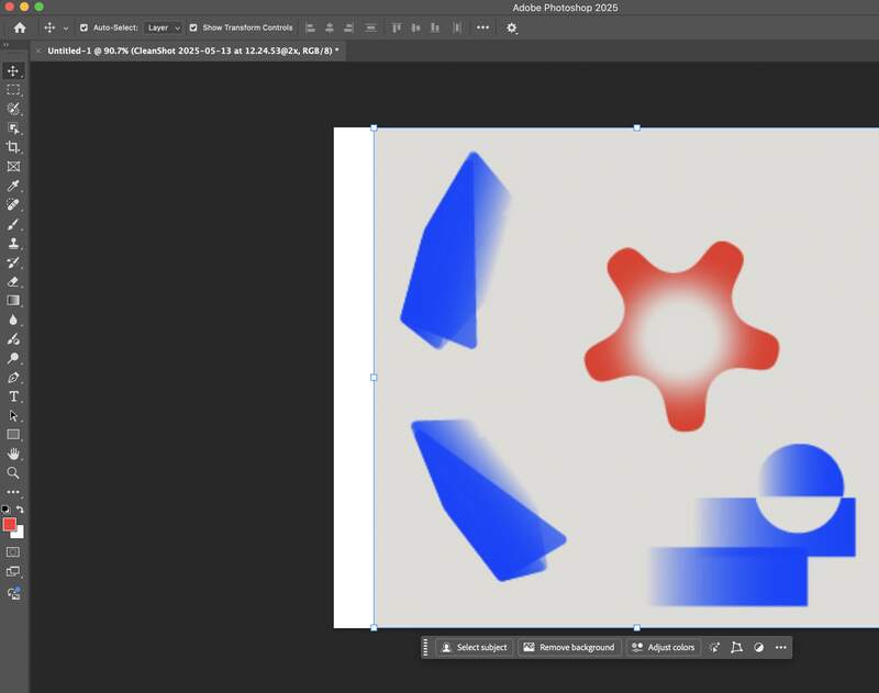
- Right off the bat, I am noticing Photoshop is pushing its Ai powered tools like generative fill, automatic background removal, and subject detection. These tools are actually pretty promising and I could see having a use for these tools within the more fully featured Photoshop environment.
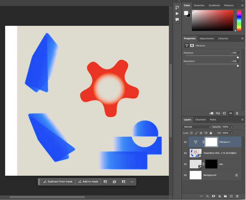
- Workflow is obviously different than illustrator in that Photoshop uses adjustment layers unlike illustrator these can be raster objects or effectors. Also your initial resolution and size setting matter a lot as you are editing with pixels and not vectors. The ordering of the effectors also matters a lot and masks can be added to limit what they effect.
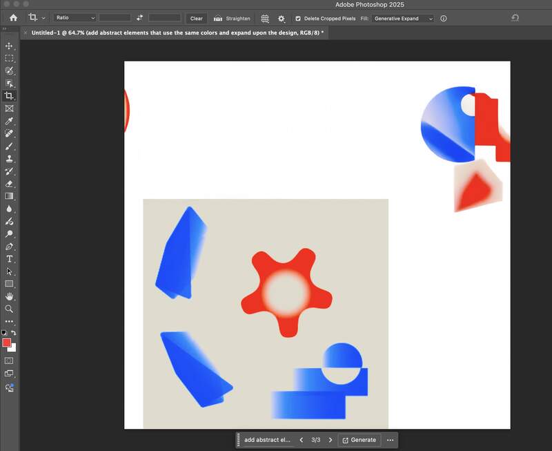
- In addition to the layering workflow you have a lot of more destructive tools on the left tool panel that allow you to crop, use advance selection techniques like lasso and destructively delete part of the image. Below I decided to use the crop tool and mess with the generative expand feature. Again it is interesting to have a more professional with more thoughtfully implemented Ai image editing capabilities. I am unclear as of now how useful this actually is for creating high quality work though.
- In sum yes photoshop is powerful. It has been almost 10 years since I have really used it and since that the interface feels a lot more streamlined. That said at this point its very hard for me to think using a workflow that is not illustrator based as that is the adobe design software I have spent the most time. If I need to do advanced photo editing / recoloring though I will definitely be jumping back into Photoshop.
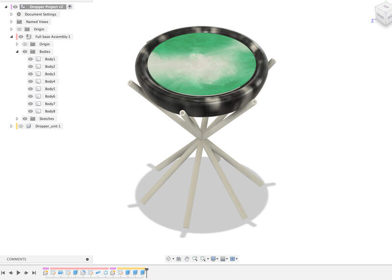
05— Final Project Fusion Test Render
What the Heck is it?
- It is a dish that holds a piece of paper. Above the dish is delta xy system that oreints a set of multiple colored ink droppers. The ink is dropped opposite to the position of the viewer only after staying still for a couple of seconds. This would probably be achieved using a fancy motion sensor or even a 3d camera like the Microsoft Kinect.
- Another concept would be to drive the whole thing with a 360 degree camera array with ai people an pose tracking… so a group of people would have to sit for a long while before the drop is released. The purpose of course would be to get a full group of people to settle into the moment in order to experience the work.
- I think the concept of having a system that uses a proxy that can tell if someone is focusing is something I would be interested in developing. I think on a basic level it wouldn’t be too hard to achieve with the most robust being using some direct brain monitoring.
Why?
- To slow the viewer down and make them focus on the work and in turn get them to focus in general. Practically all of the work I aim to create is to hone peoples focus in.
My Project Files