13—Molding and Casting
Assignment
- Group assignment:
- Review the safety data sheets for each of your molding and casting materials
- Make and compare test casts with each of them
- Compare printing vs milling molds
- Individual assignment:
- Design a mold around the process you'll be using, produce it with a smooth surface finish, and use it to cast parts.
00—Reflection
Past Experience
I have produced molds of different kinds, but I have never really tried to create a mold of my own. I have the most experience with thermal molding PETG plastic sheet that I gained from the old shop I worked at. Actually, it was one of the reasons I got the job in the first place. At the time I had been working on a 2 week contract with the company PVS Graphics in Portland, OR specifically to help them produce these thermo molded PETG parts. The project was these promotional influencer kit / food carriers for Popeyes. These custom painted plastic 6 part carriers costed $500 piece! They did not have enough people to produce these so I was hired on temporarily to help get this project out the door. There was quite a lot of post processing / painting, cleaning, painting again, printing, trimming, assembling that went into them for something that was essentially garbage.
I didn’t design the molds, but was able to come up with a reliable production process to produce the parts using our fairly basic thermo molding machine. The original molds were CNC cut and layered MDF. In hindsight it became clear that this was really not the right material for the job. The MDF was constantly delaminating from the heat and very likely off gassing formaldehyde. Below Included some photos of what the process looked like. So that said I am looking forward this week to actually making the mold part.
This Week
Priorities this week were to learn to work with molding materials, re-familiarize myself with Fusion’s CAM workspace, and also work with custom CAM post processors again in Fusion. I plan to work with the large format CNC router at IAAC for my final project and plan to program my CAM in Fusion. I thought it would be good to start with the Roland SRM-20 as a test.
Originally I was planning to devote all of my time Sunday to Wednesday to work on this weeks material, but Sunday I had to do my $$$ making work and the blackout on Tuesday in Spain made me lose a day of work. For this week I really wanted to have a lot more context to compare the different molding compounds, but I ran out of time to do the deep research I wanted to do. Mold making clearly has a lot of nuance to it. I am happy with what I was able to accomplish this week which was mainly learning to setup getting the custom post processor working with the Roland SRM-20, basic mold design for working with machining wax, and a solid workflow for mixing and pouring smooth-on fast setting silicone.
000— But first, More Preamble
Earlier in the program I did this personal project that was technically a molding process. I decided to document it here because it did require some molding techniques and learnings from working with candle wax which was my chosen part material for this week.
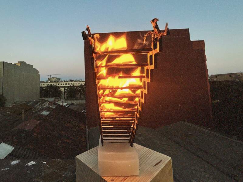
The Whole Design Process for Staircase
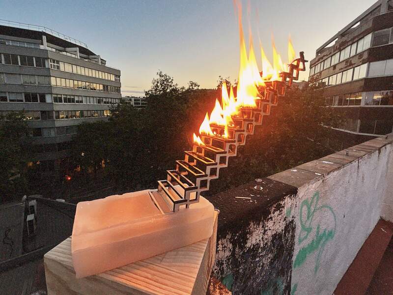
- For a long time I was thinking about making a small sculpture around the motif of a staircase. I have at the same time been fascinated by the idea of working with fire in my art work. So somehow I arrived at the idea of staircase burning… from the top down. I put this idea on hold for a few weeks until I came across this photo on Instagram of a painting by Hydeon below. It was quite serendipitous because it sort of confirmed it was at least an interesting visual motif.

- The CAD took some time to get right. The design required a parametric approach as I wanted the ability to tweak its height so I could get the right look and also easily adjust it if it created too much leverage at the base. For this reason the base was designed with plenty of holes and surface area for the casted wax to grab a hold to.
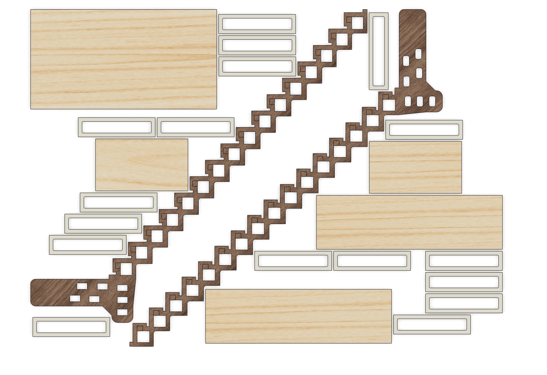
- It took 3 versions of the CAD to get all of the details right and produce a model that could easily be worked with parametrically. A big part of the design was optimizing material usage so that lever on the base would not be significant an so that when on fire the it would burn at a consistent rate. Below is the resulting CAD.
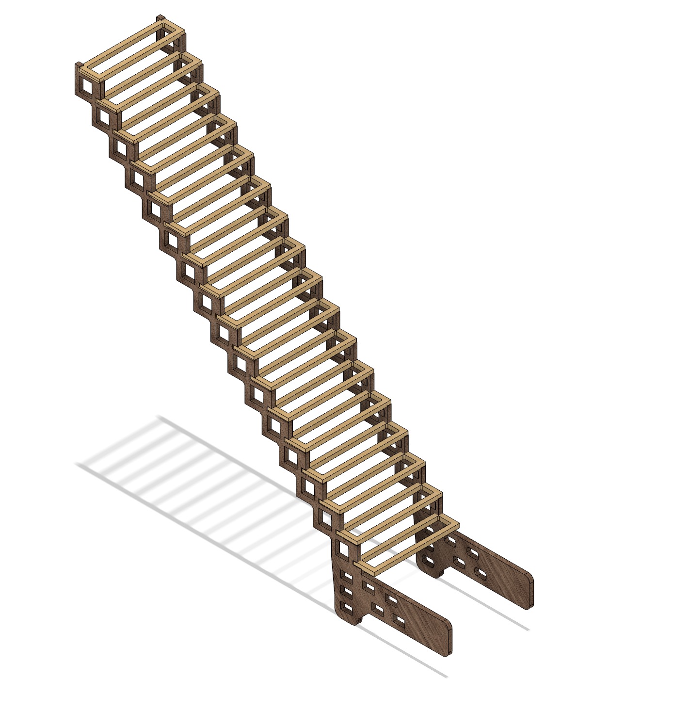
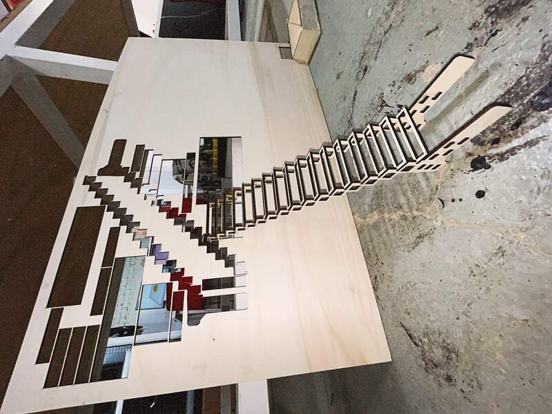
- I nested and laser cut the model and it assembled with press fits. Slots had to be hand adjusted as the kerf value was incorrect.
- Below is the resulting assembled model.
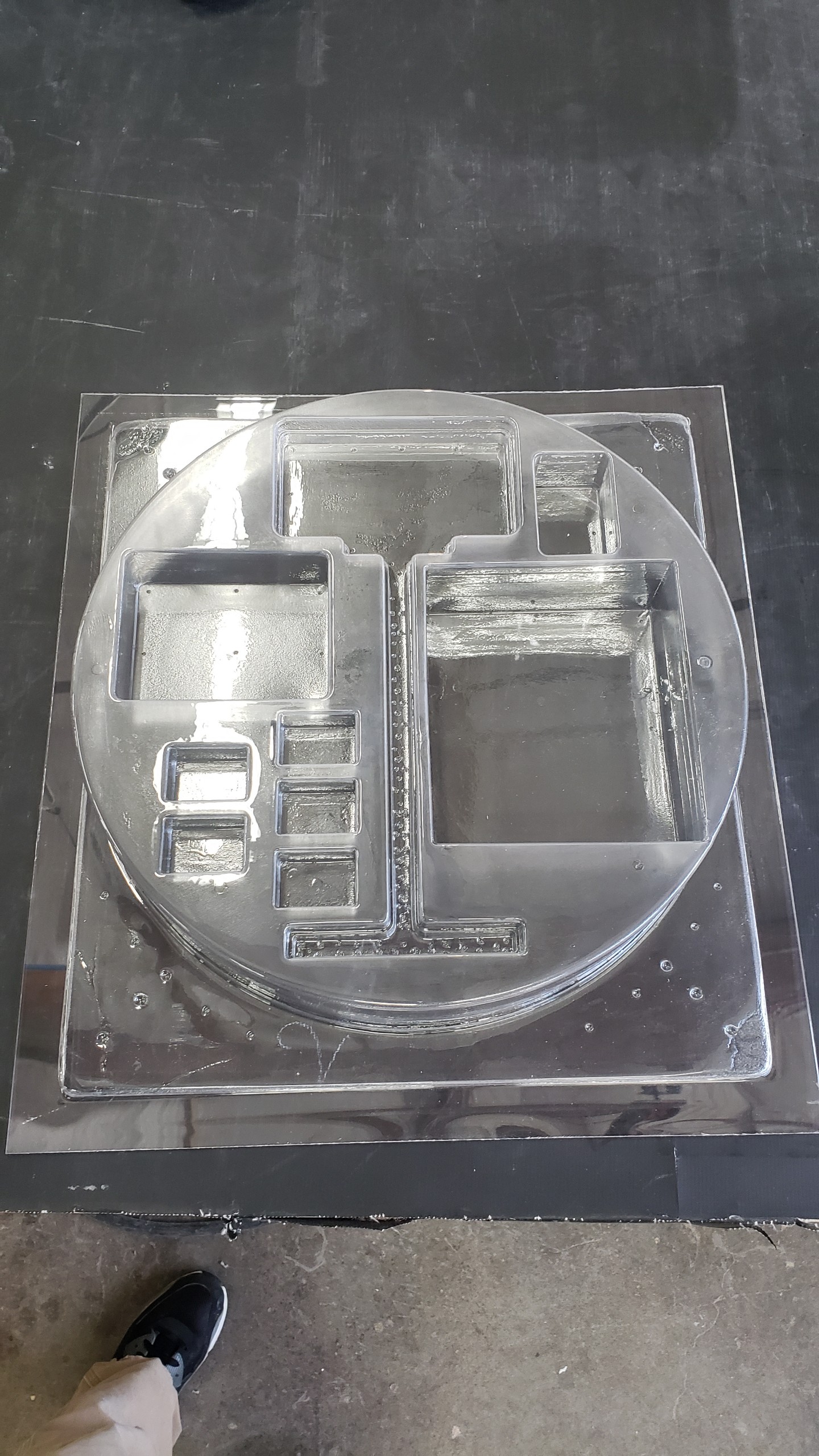
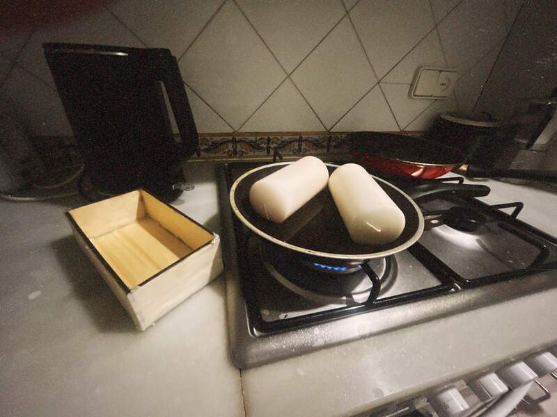
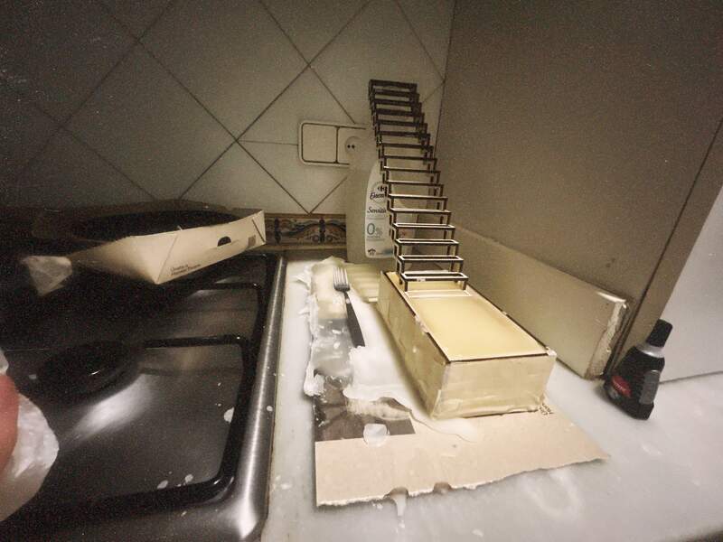
- The last step was casting the base. The candles were purchased from flying tiger as that was the cheapest place to source the wax. It was surprisingly easy to work with and clean the wax. A learning here though was to sped more time designing and sealing a more robust mold (do it does not leak) and allowed for overfilling so that I could pour to the top height without overflowing.
Final Photos ie. The Burn
01— Mold Making Basics
Important concepts
- Safety
- Stay away from fumes if you can use a respirator and or work under a ventilation hood
- Read the safety sheet
- Wear nitrile gloves
- Cover everything in paper
- Pot life
- Any 2 part epoxy will have a pot life which is how long it will last once the two parts have been thoroughly mixed.
- Paints like enamel paints typically have a pot life when mixed as well.
- Mixing Ratio
- Mixing ratios for 2 part materials are given either by weight or volume
- Curing / post curing
- Curing time— is how long it takes for the material to set once it has been thoroughly mixed
- Post curing time— curing time can be expedited if you increase the ambient temperature sometimes a datasheet provides info on this.
- Reduce bubbles — at every stage
- Proper mixing technique—When you first mix your two part material your goal is to shear the two materials together you do not want to add bubbles to the mix. To do this you do not lift up your stirring stick as you mix you simple rotate it around at an even rate over the course of the full mixing time.
- Vacuum Chamber — Its typically a good idea to further extract air through a simple vacuum chamber. The vacuum chamber can be depressurized multiple times to further extract air from the mix.
- Pouring technique— You want to pour the material at an even rate to produce a thin strand of material. Pouring like this minimizes the chance of further incorporating bubbles into the mix.
- Mold Release
- Not always necessary, but I think its worthwhile to use just in case. For a past project I used Polytek poly-ease when de-molding PETG thermo molds in the past and it worked very well.
Our Mold making workflow
About section: Many workflows exist for mold making. The differences between workflows, similar to 3D printing technologies varies quite a lot and can be very application specific. The method we are using in class can be roughly summarized as a 3 step process.
Positive: Milled Wax Buck / Resin Printed / FDM printed
- This is the first part where you create your positive form. This can be taken from a preexisting object, or 3d modeled and reproduced through milling or 3D printing.
- A few of the main terms to describe this initial part are: Positive, Master, Pattern, and Buck
Negative: Silicone / Epoxy / etc.
- This is the part where you actually create the mold. This can be made out of a variety of different materials. A common material to choose is some variation of a 2 part silicone mixture. Silicone allows for high fidelity when reproducing small details and its flexibility can allow for easy de-molding of hard materials.
- It is important to choose the right mold material. The difference in hardness between your mold and the molded material as well as the chemical interaction between the two is very important to consider beforehand.
Positive: 2 Part Polymer / Pourable food material etc.
- The final part can be called just a part or in some cases a casting.
- Material choice is similar to the set of materials used for the mold could be could be used in the final molded part.
02—Creating My Positive in Fusion
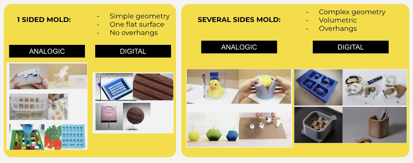
Mold Design Types Simple Overview
CAD Modeling process in Fusion
*I have omitted details that are more general to 3D modeling in Fusion.
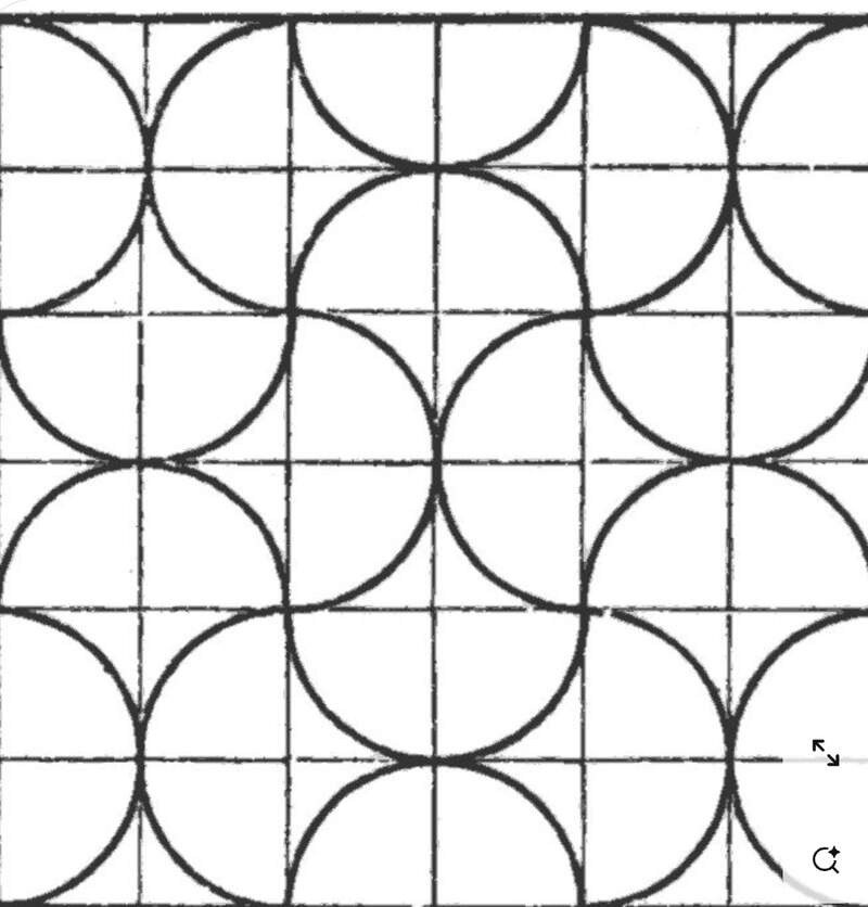
- The concept—I wanted to create something that would be a very simple first test of the molding process while still producing an interesting result. For this week I wanted to see if I could create a design that is based on 2 tessellating tiles patterns with small channels that could funnel lighter fluid. Ideally when ignited the channels would create a ‘chasing’ effect throughout the design. Below was a reference design I found on Pinterest when doing some visual research for the idea.
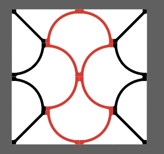
- Sketching in Illustrator— After a few hours of playing around I settled on an hour glass motif for the design. It took some more time to confirm that the design would tessellate properly and that the design could pass the lighter fluid between the tiles. To solve this problem I added these little junction squares to the tile patterns. Below is the final design, but I have also included the Ai file if you want to look at other ideas I explored. The black and red lines are where the inset channels are in the design.
- Creating the mold in fusion—
- I pulled the sketch lines out of Illustrator by converting them into SVGs and re-scaling them to fit the 50mm x 50mm square tile. Below is a photo of one of the finished tiles.
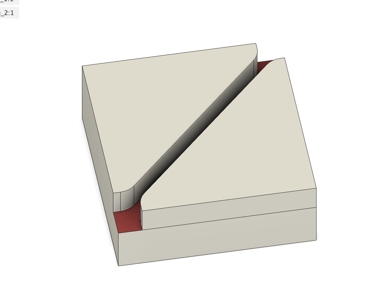
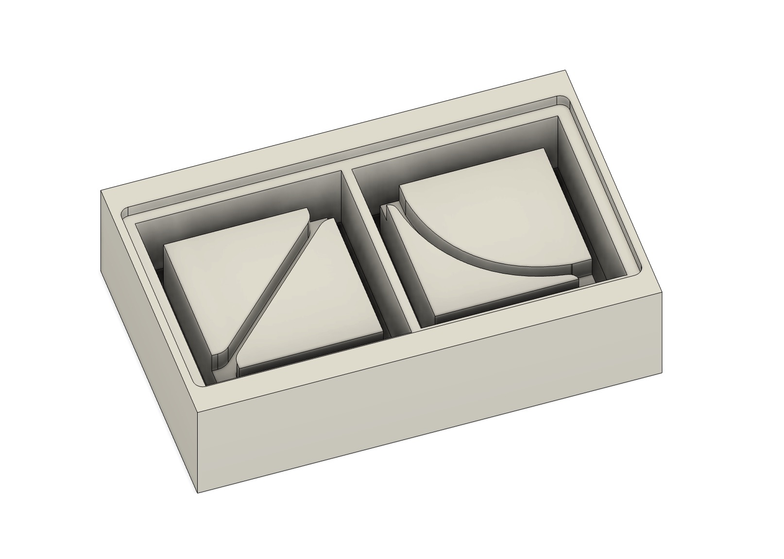
- I then had to create my molding buck with the two pucks I had designed. This took a bit of mental gymnastics as I had to make sure to think carefully through the milling process and the resulting silicone mold. I added about 6mm of extra material on the bottom and side around the tile positive shapes to give the mold enough structure. Draft angles were omitted because I figured I could get away without using them. Really this was not a problem because of the nature of the design and the molding silicone I used. However, if I did it again I would add draft angels to the channels in the tiles because I thing they would improve the movement of fluid within them.
- I pulled the sketch lines out of Illustrator by converting them into SVGs and re-scaling them to fit the 50mm x 50mm square tile. Below is a photo of one of the finished tiles.
03—Group Project and Reflection
The group project was just an extension of our in person experience and our 1 on one conversations with each other. Not a lot was gained from this assignment. My primary learning from this week was don’t use silicone molding materials if you cant ensure the freshness. Also FDM 3D printing is a totally reasonable way to make a mold positive if you start at a low layer height and sand and fill your mold.
Check out the group project here
04— Fusion CAM and 3D Milling workflow for the Roland SRM-20
Setting up the Fusion CAM file
I was pretty rusty with Fusion CAM especially for 3D milling. The points I am making below are common sense things to do, but there is a lot I am missing about specifics. A lot of these specifics about what tool paths to use when are simply things I have forgotten and I unfortunately did not have enough time to do a deep dive into this. Ultimately, though since the milling material is wax I had a pretty big margin to work with when choosing things like speed and feeds.
While speeds and feed settings were fine I would not recommend following my machining approach exactly. The approach I took is just the one that allowed me to clear all of the material to create positive model it took about 2 hours of mostly fiddling with different path types to achieve this. Even still I would need to do more research to improve the surface finish on the part as it had some spots where the tool jabbed into the material.
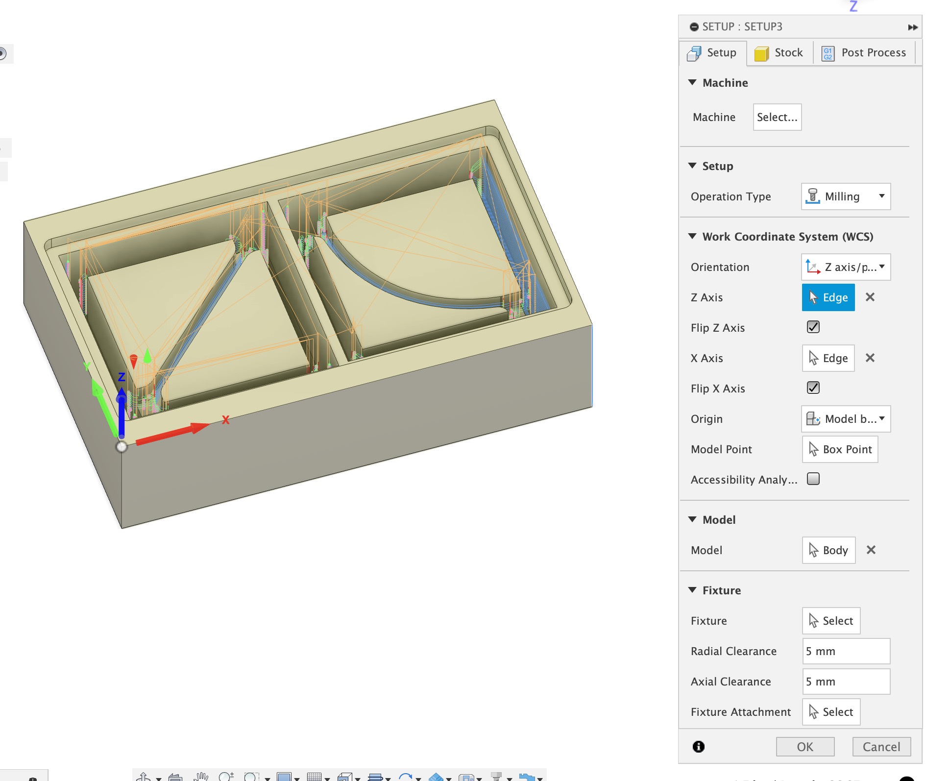
- Once you are in the Fusion Manufacture space you need to create your setup. I used a fixed box size with no additional stock added. I always set up my stock from the bottom left. The tutorial I found for working with the SRM-20 showed the coordinate orientation. I followed this exactly because if I remember correctly each machine sets its X Y and Z coordinates differently.
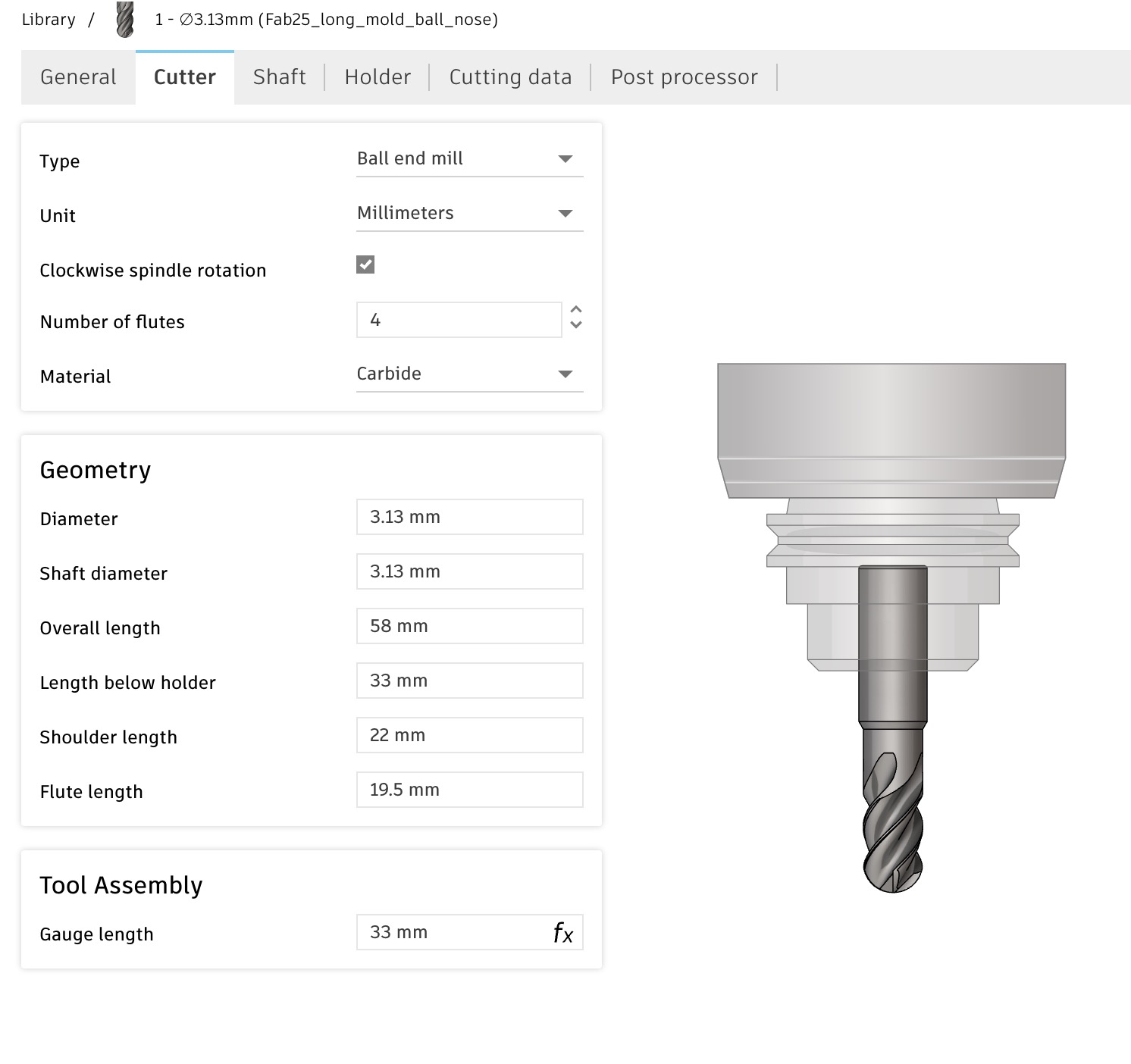
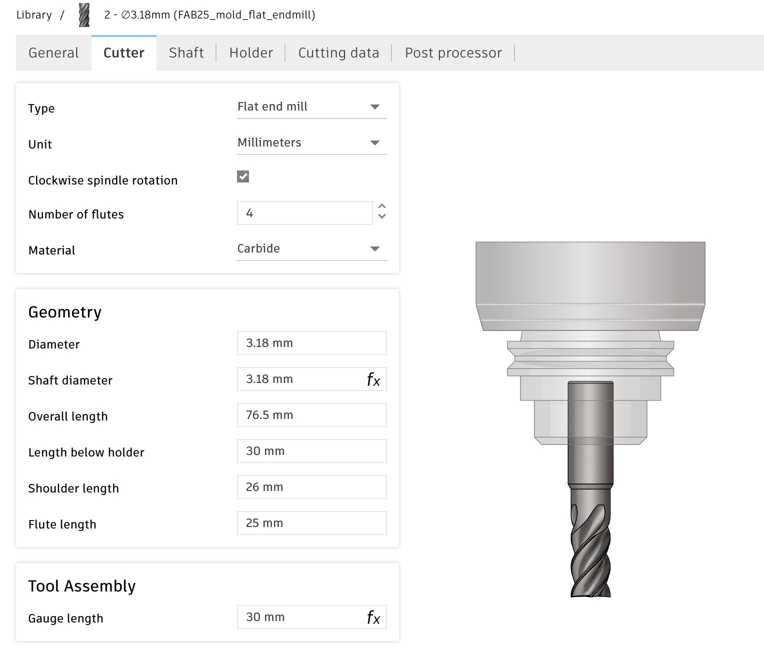
- Create your custom tools. In this case I used a flat 1/8” endmill and a ball nose 1/8” endmill. These were the longest bits we had and I needed them because I needed to mill deep cavities in my mold.
- I chose a
3D Adaptive Millingtool path first with the following settings. 1500 mm/min is proved to be somewhat aggressive but I saw it in another tutorial and it worked fine. Settings in the passes tab were mostly default. This caused no issues but I might have backed off to about 1200mm/min. *spindle speed should have been set to 7000 RPM.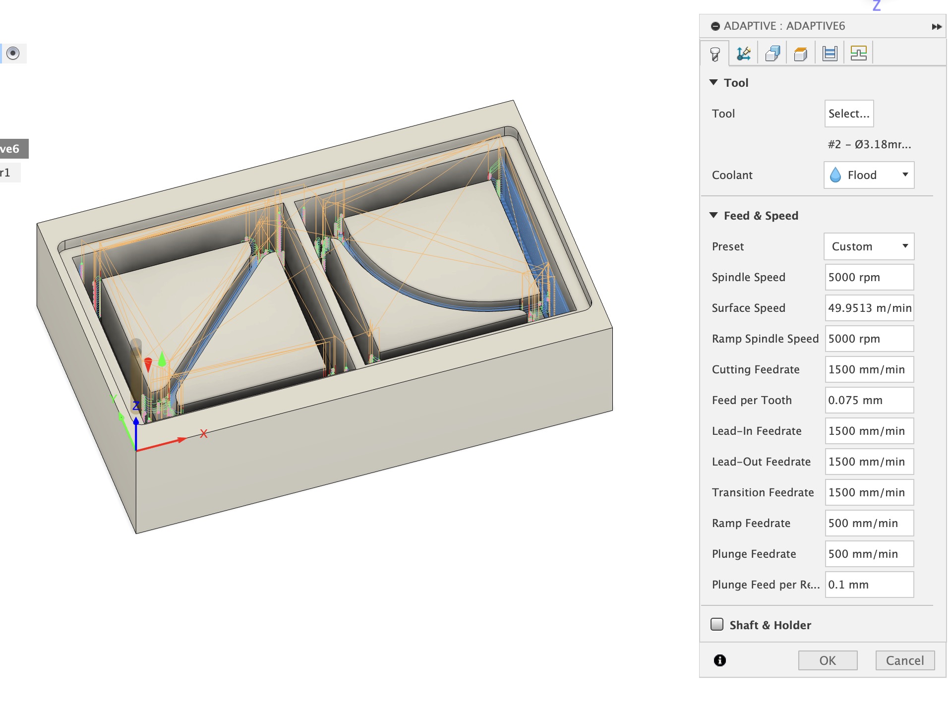
- For the second tool path I used a 3D
contour pathwith the following settings for speeds and feeds.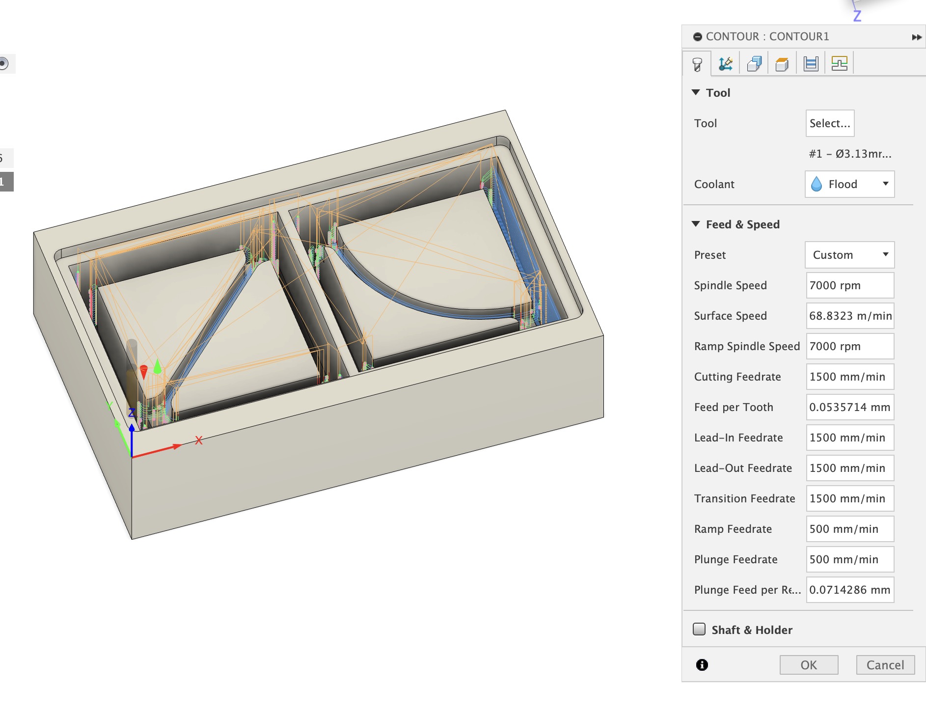
Posting out to the Rolland SRM-20
I actually did this part first and ran a dummy file on the mill to confirm the post processor was working correctly. I would recomend doing this when you are running custom post processors for the first time.
- A quick google search turned up great Fab Lab documentation about doing exactly this which can be consulted here. Several other people have used Fusions CAM with this Mill, but this was the best guide I found.
- First you need to add the new post processor into the manufacture space. First click open the post library by clicking the
Post Libraryin the manufacture workspace. You search the file which is “Roland RML” and simple drag it into your local folder.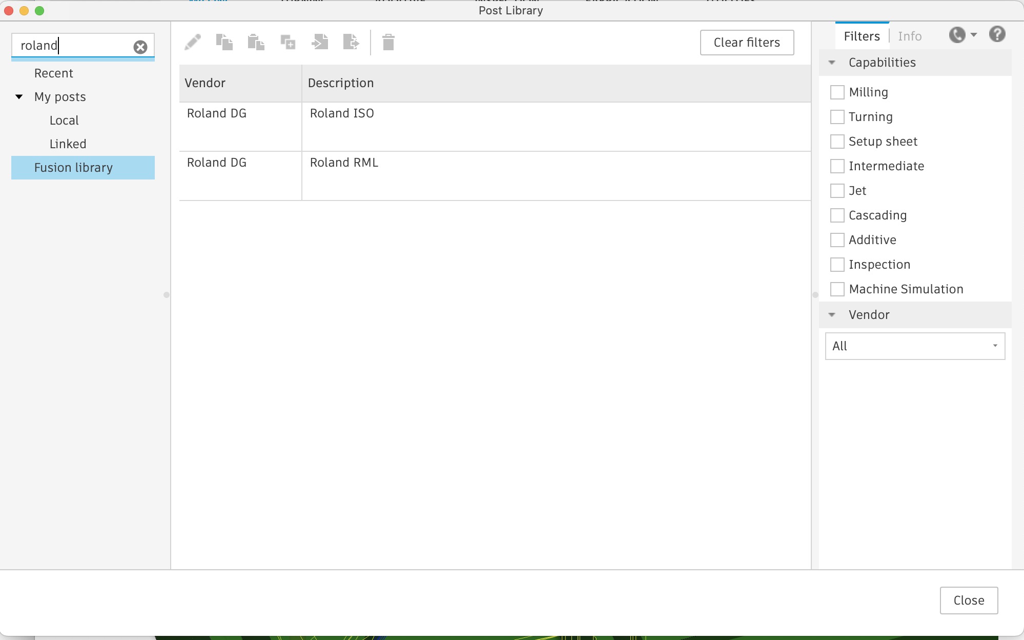
- With your finished CAM all you have to do is post-out from each individual rendered tool path. To do this you right click the tool path and click
post process. Also the file output is .prn instead of .rml This is not an issue.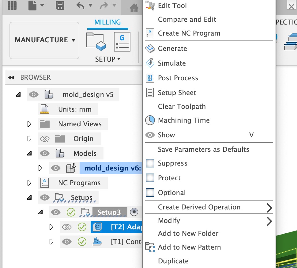
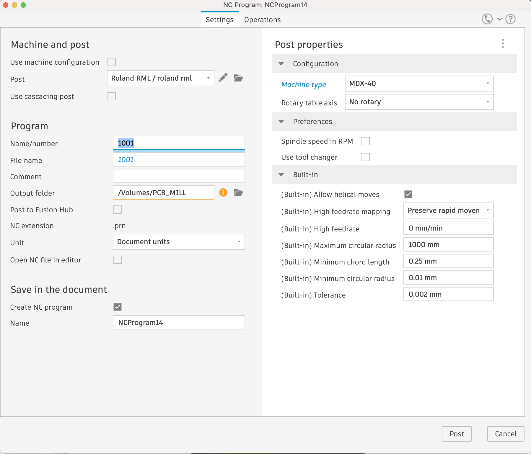
- The below dialog appears. The only thing I change here beyond renaming is selecting the Roland MDX-40 from the machine dropdown. This post processor is not actually made for this mill, but is similar enough to be used. Just a heads up it produce a .prn file not a .rml file the machine controller can take both.
- You are ready to go!
05— Milling the Positive on the Roland SRM-20
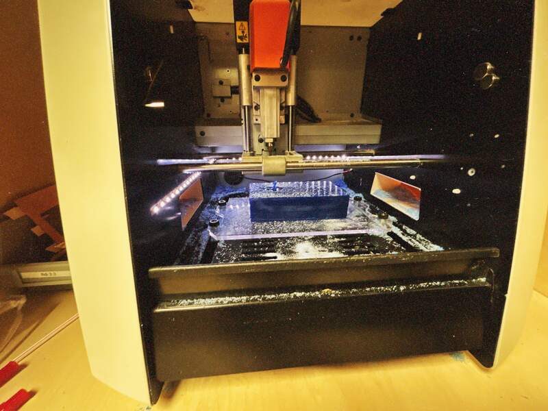
This process is basically identical to milling FR-1 based circuit boards. Since I am milling deep cavities it was important to confirm that the standout of my milling bit matched the setting length below holderI had specified in the custom tools I created in fusion. This ensures that the collet will not collide with the stock.
- Securely mount your wax block square with the bed using double sided adhesive tape.
- Go through your tool loading / homing routine.
- Load your file.
- Run your file
- Repeat if you require tool changes.
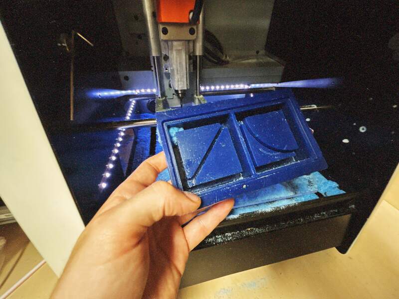
- Below is the result of the milling.
06— Prepping and Pouring the Molding Silicone
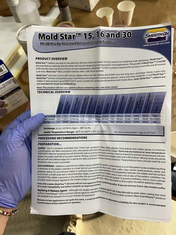
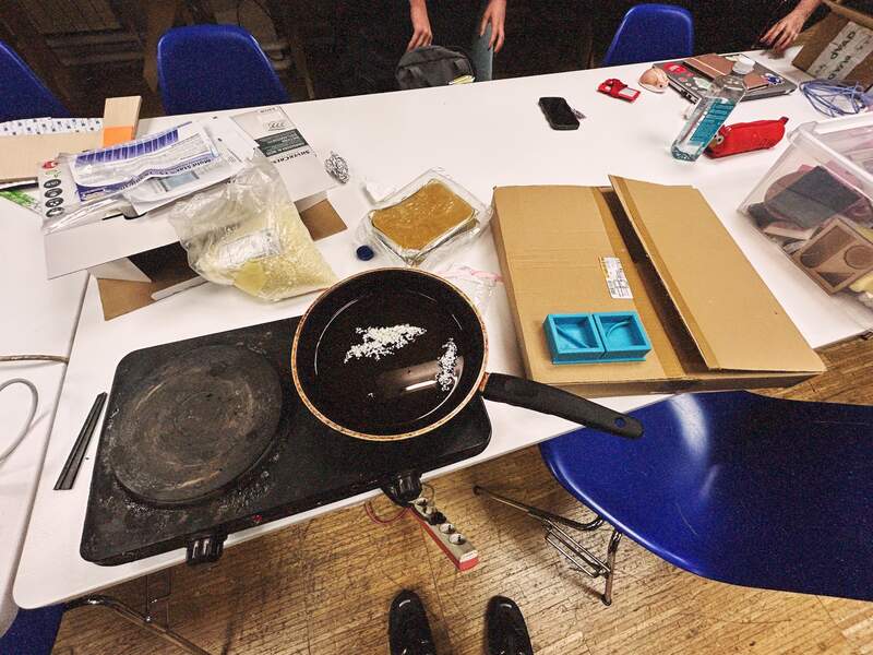
I chose to use a fast casting silicone from the well known brand Smooth-On because Ive seen this brand for years and people seem to love it. I chose the fast casting version because I knew it should be easy to mix and I could easily make several attempts in a short time if the first attempt did not work. The preparation for the Mold Star 16 FAST was very straightforward. There were however some nuances to preparing two part silicone that I only learned while actually mixing and pouring the compound.
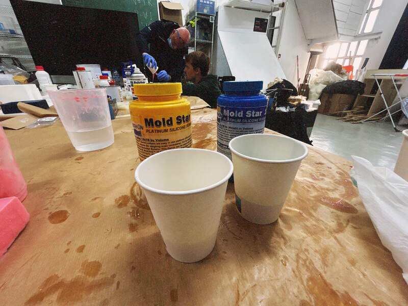
- I put on my gloves and watched the video included on the box. Super simple.. the Mold Star 16 FAST has an A and a B part that are mixed in equal ratios. Cure times and other details below.
- Before I started the bottles needed to be thoroughly mixed. I used separate wooden popsicle sticks to mix them individually. I am not sure how long or what I was supposed to be looking for in order to ensure they had been well mixed. Either way I just mixed them for about 1.5 mins each. In hindsight I might have mixed them longer.
- I zeroed my scale and filled my mold positive with water. The resulting weight was 150 grams. This meant I needed 75 gram for both my A and B parts.
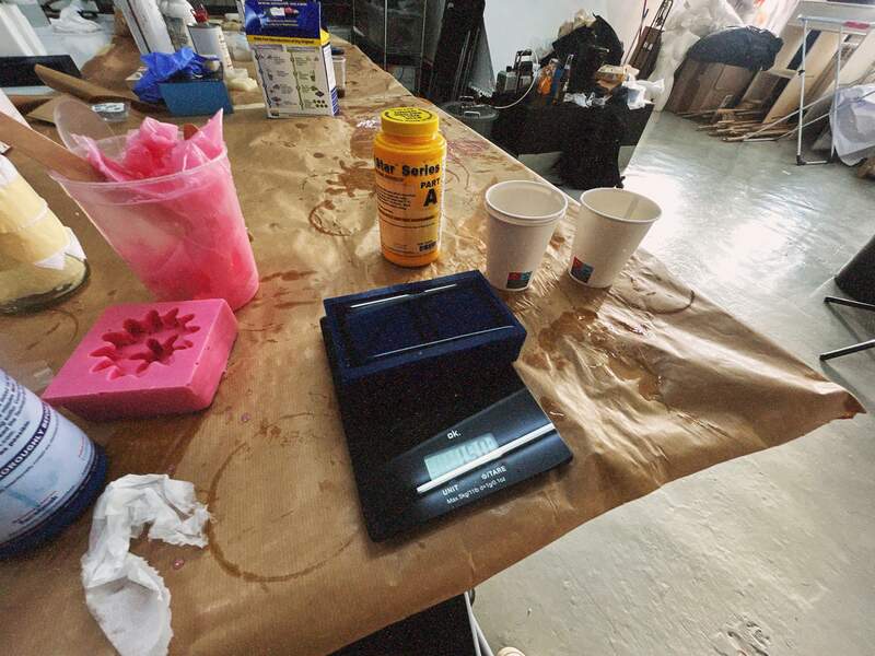
- I poured each in a separate cup on the scale and stopped at exactly 75 grams for each compound.
- I stupidly… poured it into a 3rd cup. Next time it would be better to pour it into 1 of the A or B compound cups. Something I did not consider was that it is very important that you get all of the mixture out and you leave none left in the cup as anything left over means that you ratio between you A and B mixture will be off.
- I vigorously mixed for 2 min making sure to scrape the side as I went.
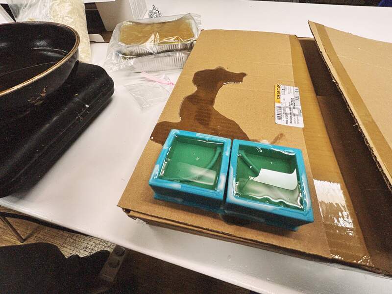
- I poured the mixture into the mold with as thin of stream as possible pouring about a meter above the piece so as to reduce bubbles.
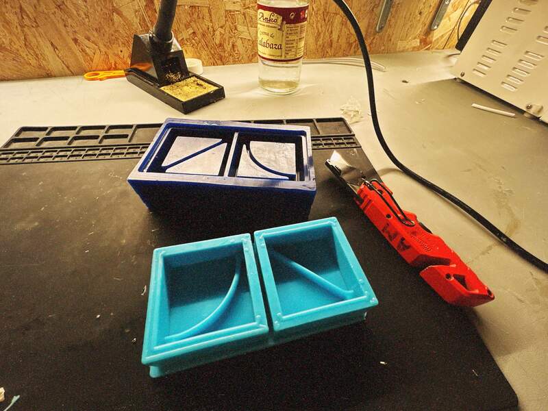
- Set time was ridiculously fast 30 min, I removed the mold about an hour later and it had no noticeable voids and was easy to de-mold.
07— Pouring the Beeswax Parts
This part was super easy. However, I think the mold design should have included a rigid body (like a 3D printed part) so that the wax tiles had straighter edge lines. Similarly a top piece to the mold to keep the bottom of the tiles flat would have also been an improvement.
- I estimated the amount needed and turned on the heater and the beeswax melted quickly. I tried not to overheat it so as to decrease the cooling time.
- I poured the beeswax into the silicone mold.
- Set time was about 30 minutes but ideally I would have waited more like an hour.
- Molding all 16 takes time will have photos below when finished.
Project Files
References
- Chat GPT question “What are the primary terms used for the different kinds of 3D parts that are needed to create a mold. Like the term positive negative buck etc”
- Consulted Nadieh’s excellent documentation on mold making for my notes. https://fabacademy.org/2021/labs/waag/students/nadieh-bremer/blog/week-12/#creation-of-the-wax-mold
- Fab Academy BCN’s Lecture Page https://fablabbcn-projects.gitlab.io/learning/educational-docs/fabacademy/classes/13-Molding%26Casting/