6. Electronics design
This week I am going to take a look at some equipment used in electronics like a power supply, AVO-meter and an Oscillosope and take a look at what is going on. I will aslo design a extension board for Seeed with connections for each pin and some buttons, push and slide. Maybe I will have time to design a case around it.
Group assignment:
- Use the test equipment in your lab to observe the operation of a microcontroller circuit board
Individual assignment:
- use an EDA tool to design a development board that uses parts from the inventory to interact and communicate with an embedded microcontroller
- extra credit: try another design workflow
- extra credit: simulate your design
- extra credit: design a case around your design
Useful links
Group Assignment
I didn´t know exactly what I should do for this assignment so I decided to hook up a power supply, oscilloscope and a AVO meter and take a look at the signal.
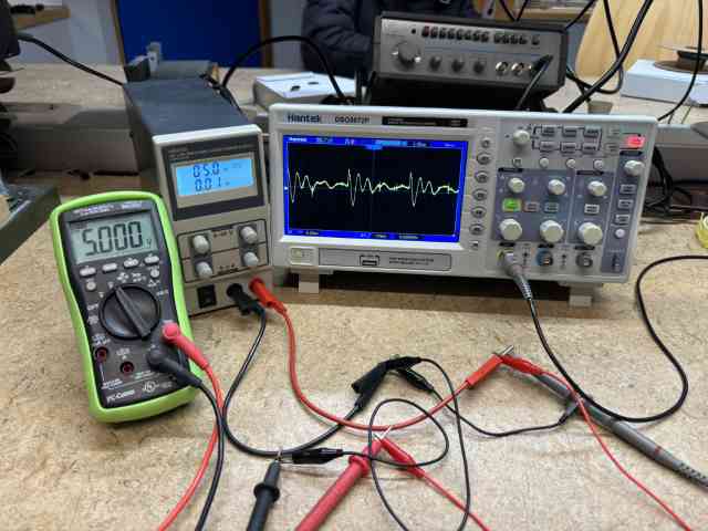
Here I am looking at 5V from the power supply. The signal is a little fussy but all the equipment agreed on the voltage.
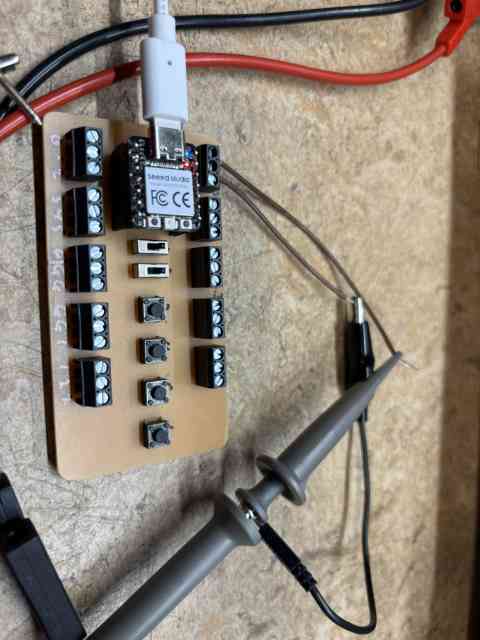
Then I hooked the Seeed up to the USB port of my computer and hooked the 5V pin up to the scope.
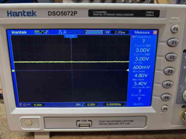
The signal was a little fuzzy like from the power suply and the peak to peak was 600mV.
Individual Assignment
I decided to desigh a extension board for my Seeed Studio. I do not like breadboards ond pins for prototyping so I am going to desing a aboard with screw connection. Maybe I will add some push buttons and slide buttons to be used for testing.
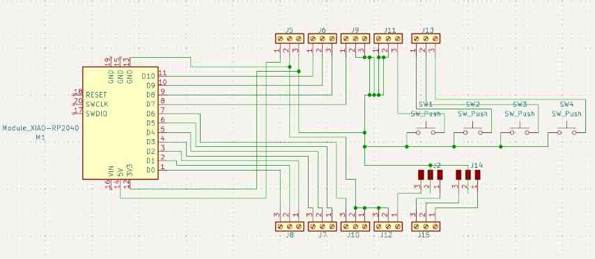
Here the design is being made in KiCad Schematic.
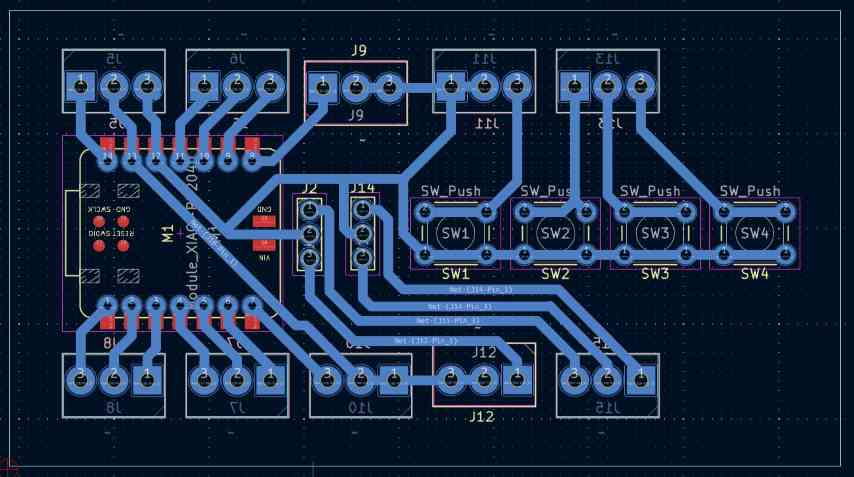
Here I am designing the board it self. Where the componets will be located.
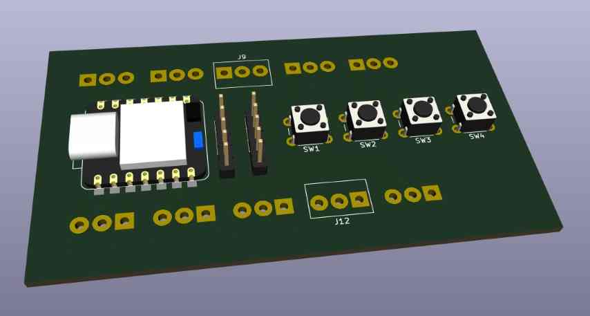
Here is the 3D view but with some 3D models missing, have to look into that.
Above is the Seed Expansion board project in a Zip file.
I did not do anything for extra credit. I did not try another workflow, I only used KiCad, I did not simulate my design and I did not design a case around my design.