4. Embedded programming
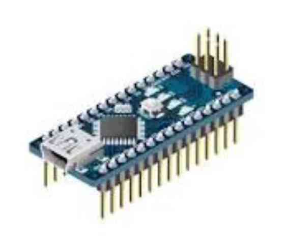
This week I am going to compare two different microcontrollers. Arduino Nano, which I have been experimenting a little with in the past and Seed Studio XIAO RP2040.
Group assignment:
Demonstrate and compare the toolchains and development workflows for available embedded architectures.
Document your work to the group work page and reflect on hyour individual page what you learned.
Individual assignment:
Browse throught the datasheet for your microcontroller.Write a program for a microcontroller, and simulate its operation, to interact (with local input &/or output devices) and communicate (with remote wired or wireless connection).
Useful links
- Arduino Nano Manual
- Getting Started with Seeed Studio XIAO RP2040
- Getting Started with Seeed Studio XIAO ESP32C3
Toolchains
Arduino-Nano
When writing a code for Arduino, i start by opening Arduino IDE (or Wokwi like I also did this time). In IDE I have to select which board I´m using, Nano in this case and which port of the computer the Nano is connected to.
In the code I have to define the pins I use, in this case, Analog 0 for the potentiometer and Digital 9, which is a PWM (Pulse With Modulation) pin I can use as a output for the LED.
In Void setup I have to set the mode of pin 9, define it as a output.
In void loop, I have to tell the board to read the input of A0. That gives an input of 0 to 1023.
Then i have to map that number to 255 so I can send an output of 0 to 255 to the led pin.
Then IDE has to verify the code and compile.
Once the code is error free it can be downloaded to the board.
Then I added serialprint to the code so that I can see the value of the potentiometer and the value of the LED.
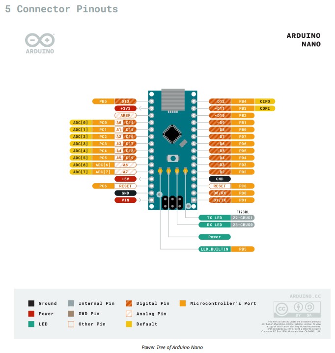
The image above shows the Arduino Nano pinout diagram, detailing the board's power, analog, digital, and communication pins.
It highlights power connections, analog inputs, digital I/O pins, and communication interfaces, the built-in LED and RESET pin.
This diagram serves as a reference for connecting components and peripherals to the Arduino Nano.
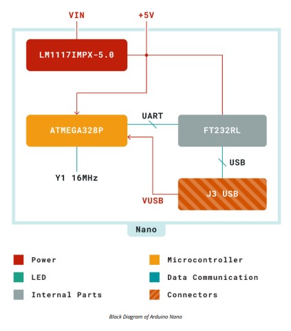
This image shows the block diagram of the Arduino Nano, illustrating its power, communication, and internal components.
This diagram provides a structural overview of how the Arduino Nano operates internally.
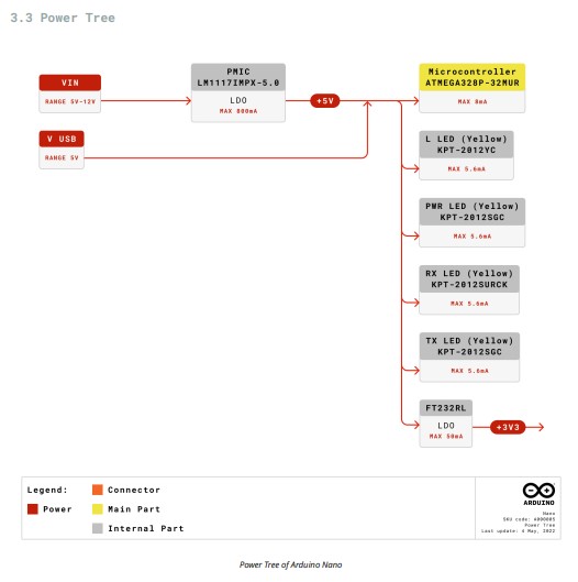
This image illustrates the Power Tree of the Arduino Nano, showing how power is distributed across the board and it provides a clear overview of how power flows through the Arduino Nano, ensuring proper operation of all components.
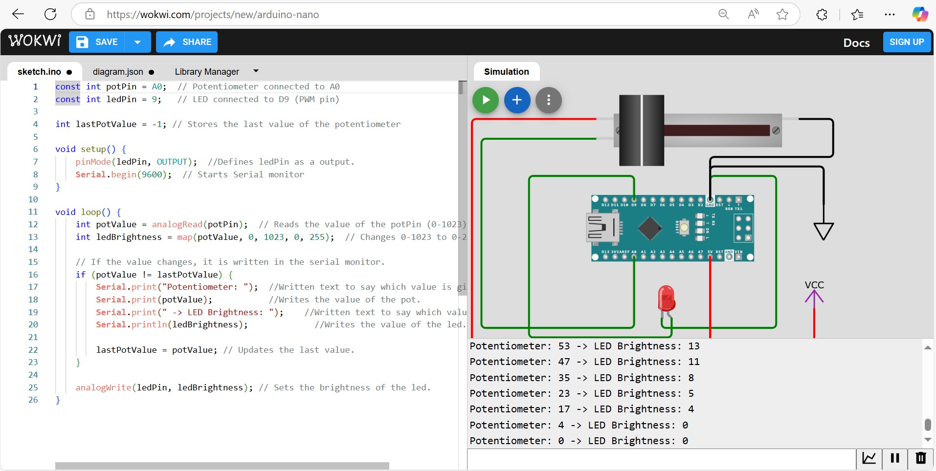
This image shows a Wokwi simulation of an Arduino Nano controlling an LED brightness using a 10kΩ potentiometer. In the code you can see that the A0 reads the analog value, which is then mapped to a PWM range to control the LED.
The serial monitor displays real time updates of the pot and the LED. Wokwi can help us visualize how the circuit and the code work to dim or brighten the LED.
Here is a video of the arduino running the code with a 10k potetiometer and a LED.
On the screen you can see the print screen commands. Pot value 0-1023 and the LED value 0-255.
Problems and problem solving
I ran into some serius problems. When I was uploading the video from the Arduino experiment, I forgot to downsize og compress the video. At the time of upload, the video was aprox. 20MB and that was a problem.
I relized the mistake and tried to fix it but the big file was already in the system, blokking everything else. Some Q&A on Discord with fellow Icelanders did not fix the problem so I had to go to Fablab Akureyri and get Árni Björnsson to fix it with me.
Anyhow, the problem is fixed and I´m up and running again.
Then I had another problem. My instructur suggested a different aproach for the video link, even gave me an example.
When I was copying the link, the last command was left behind resaulting in the tab being incomplete. Therefore, the rest of the page was not displayed anymore so I had to have him look at it and help me find out what was going on. But all of this is a part of a very steep learning curve for með since I have not had any previous experience with html.
•Þetta er tilraun til að nota punkt fyrir framan uptalningu.
Seeed Studio XIAO RP2040
Ok, on to Seeed Studio XIAO RP2040. I have never touched this before and but I have to step outside of the Arduino box and try it. Not knowing how to write code in micro-python, I surrendered my self to AI to write a code.
After reviewing both codes, the code for the RP2040 seems much simpler.
To write a code for Seeed Studio I had to download a program called Thonny.
Then, like I said, got AI to write a code for me similar to the one I wrote for Arduino.
What I asked the AI was: Can you write a code for Seeed Studio XIAO RP2040.
I will be using Thonny to upload the code.
I wanna use a 10k potentiometer to dim a LED.
Can you include serial print for me too.
I had to import some libraries for GPIO, ADC, PWM control and time.
Then I had to define pins for potentiometer and LED, just like for the Arduino.
Set PWM frequency for smooth LED dimming.
Insert a variable to store the last pot value so changes can be detected.
Read the pot value. Python uses 16 bits so the values are 0 to 65535 but not 0 to 1023 like the arduino.
Put in a variable for only updating the LED value if the pot value changes more than 500.
Print current value to serial monitor.
Update the last pot value.
Once the code is ready, I could push "run the current script" and Thonny would upload the code to the Seeed Studio.
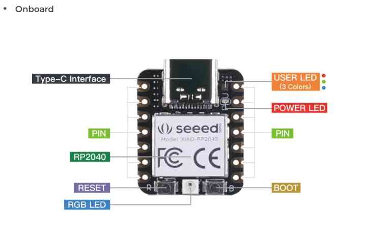
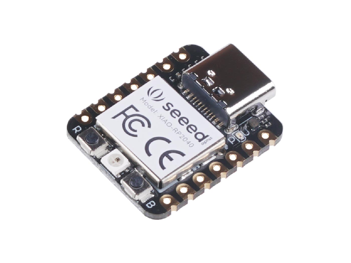
This image shows the Seeed Studio XIAO RP2040 development board with labeled onboard components.
- Type-C Interface - Used for power, programming, and data transfer.
- RP2040 Microcontroller - The dual-core ARM Cortex-M0+ processor powering the board.
- User LED (3 colors) - Multi-color LED for user-defined applications.
- Power LED - Indicates when the board is powered.
- BOOT Button - Used to enter bootloader mode for flashing firmware.
- RESET Button - Resets the microcontroller.
- RGB LED - Built-in multi-color LED for status indication.
- GPIO Pins - Multiple digital, analog, PWM, I2C, SPI, and UART capable pins for external components.
- Processor & Core System
- Memory & Storage
- Peripherals & I/O
- System Control & Power Management
- USB Interface
This diagram provides a clear overview of the hardware features of the XIAO RP2040.
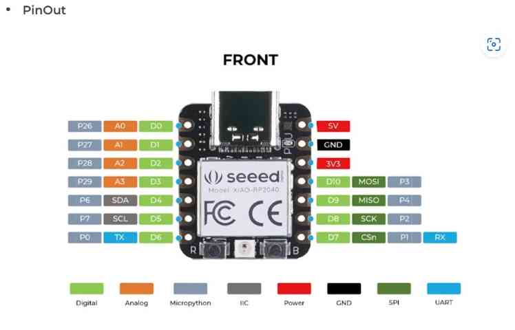
This image shows the pinout diagram of the Seeed Studio XIAO RP2040, detailing the board’s digital, analog, power, and communication pins.
This pinout diagram provides an overview of the GPIO and communication capabilities of the XIAO RP2040.
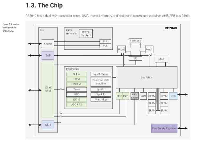
This image presents a block diagram of the RP2040 microcontroller, illustrating its internal architecture and key components.
This diagram provides an overview of the RP2040 architecture, showing how its processor, memory, peripherals, and communication interfaces are interconnected.
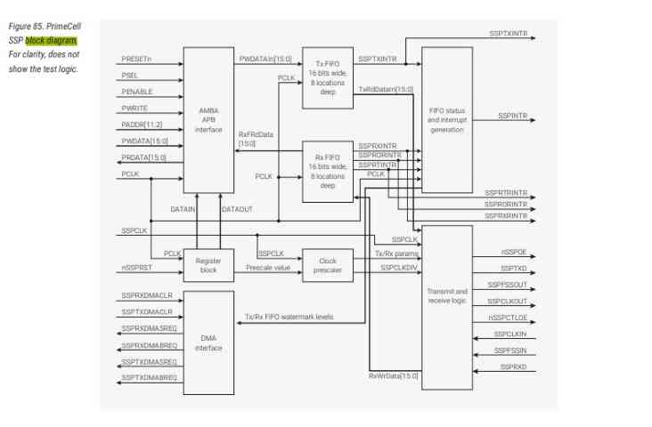
This image shows a block diagram of the PrimeCell SSP (Synchronous Serial Port) module, which is part of the ARM architecture.
This SSP module is used for SPI, SSI, and Microwire communication, making it a key component for serial data transfer in embedded systems.
Compare the two different codes
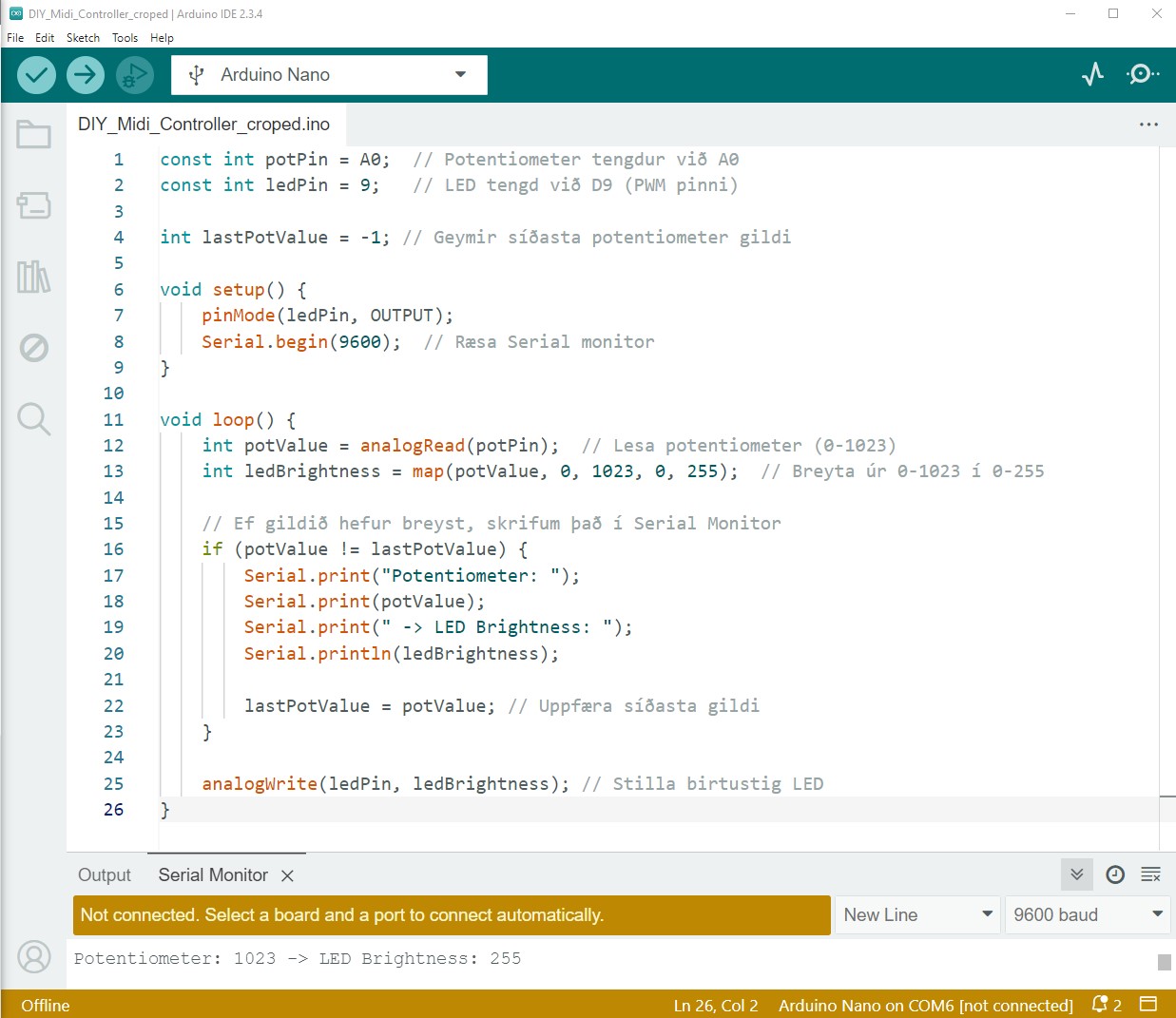
This is the c or c++ code written in Arduino IDE.
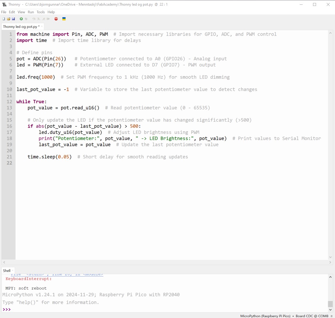
This is the Micro Python code written in Thonny.