Week 04. Embedded Programming
Introduction
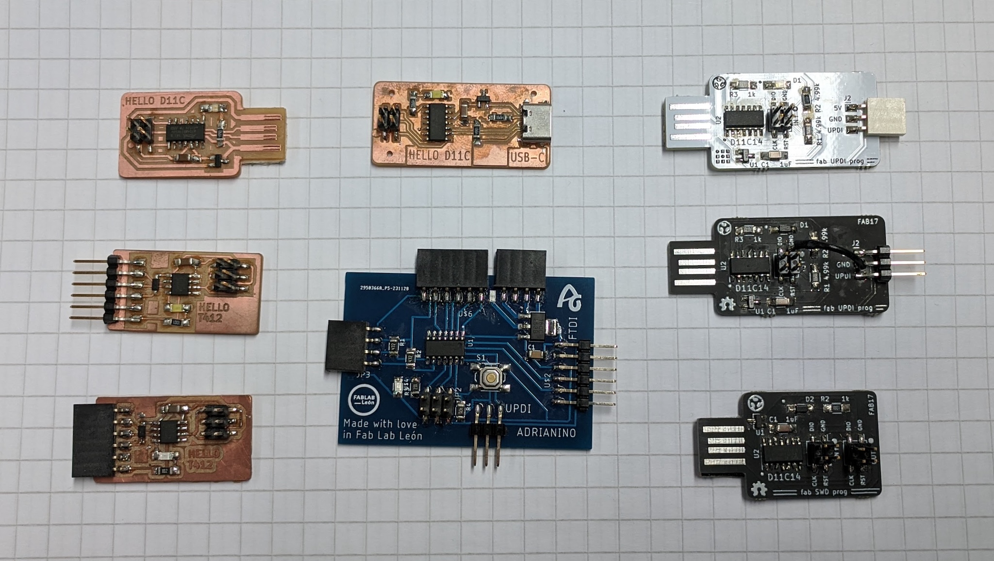
We started by looking at several microcontrollers and learning how to interface with the Arduino IDE to program them.
| Board name | Architecture | Clock speed | Price |
|---|---|---|---|
| Hello ATTiny | AVR 8 bit | 20 mhz | $0.50 |
| Hello D11C | ARM 32 bit | 48 mhz | $1.50 |
| Seeed XIAO RP2040 | ARM 32 bit | 133 mhz | $4.50 |
Programming
Simulation
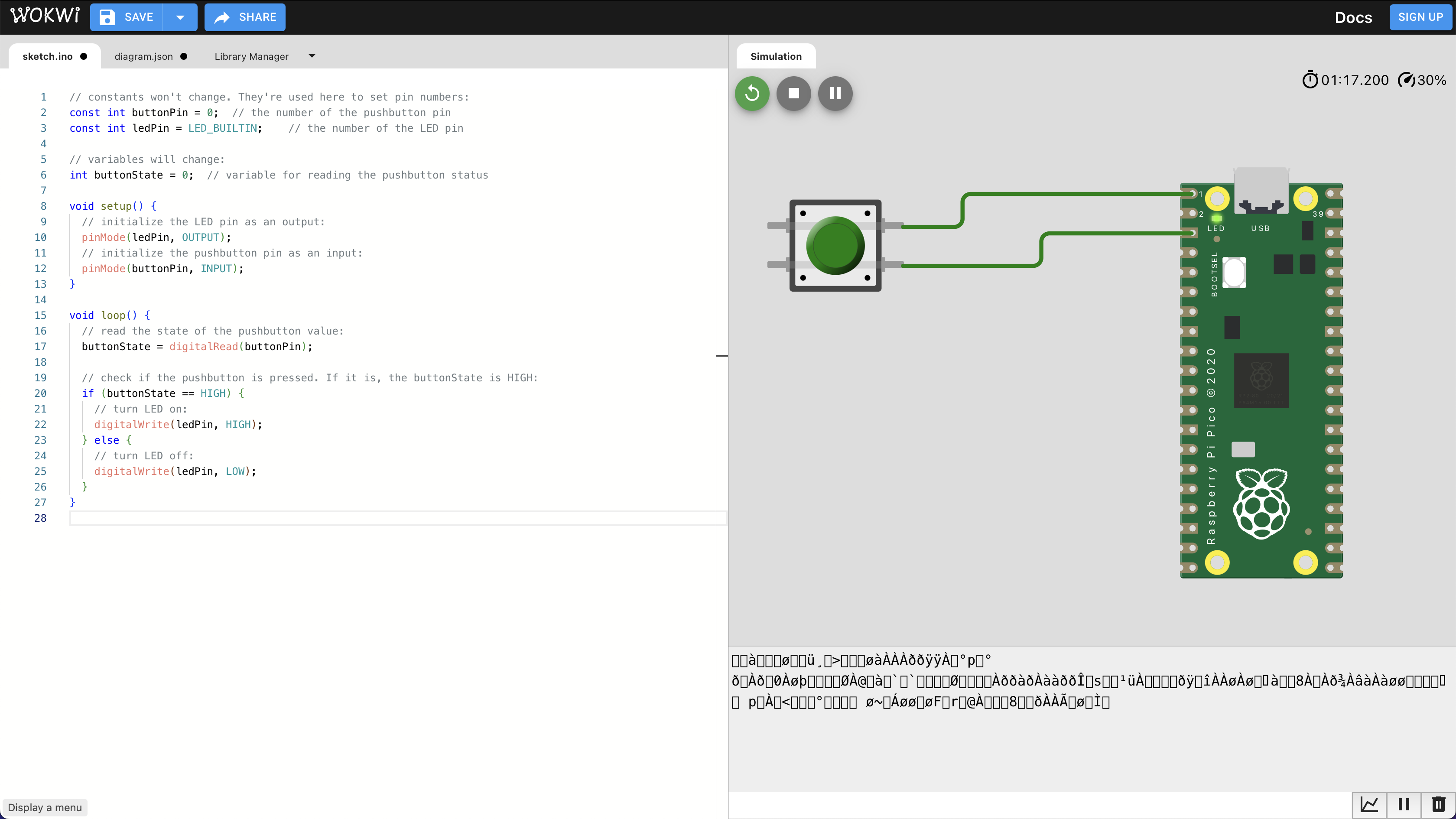
The basics seem to work, although the compilation server might have been stressed with Fab Academy students. The LED turns on and off with the button presses, but it doesn't seem to update with the loop. If I do more with this kind of simulation, I'll try the local version.
Setting up Arduino
Install Arduino IDE.
Follow directions on Seeed XIAO RP2040 wiki to make it available in the Arduino IDE board manager.
v0 - Blinking LED
The most basic example program works once you select the correct board and upload it.
// the setup function runs once when you press reset or power the board
void setup() {
  // initialize digital pin LED_BUILTIN as an output.
  pinMode(LED_BUILTIN, OUTPUT);
}

// the loop function runs over and over again forever
void loop() {
  digitalWrite(LED_BUILTIN, HIGH);  // turn the LED on (HIGH is the voltage level)
  delay(1000);                      // wait for a second
  digitalWrite(LED_BUILTIN, LOW);   // turn the LED off by making the voltage LOW
  delay(1000);                      // wait for a second
}
However, I noticed that there are multiple colors of LED in the same space, and only red is blinking.
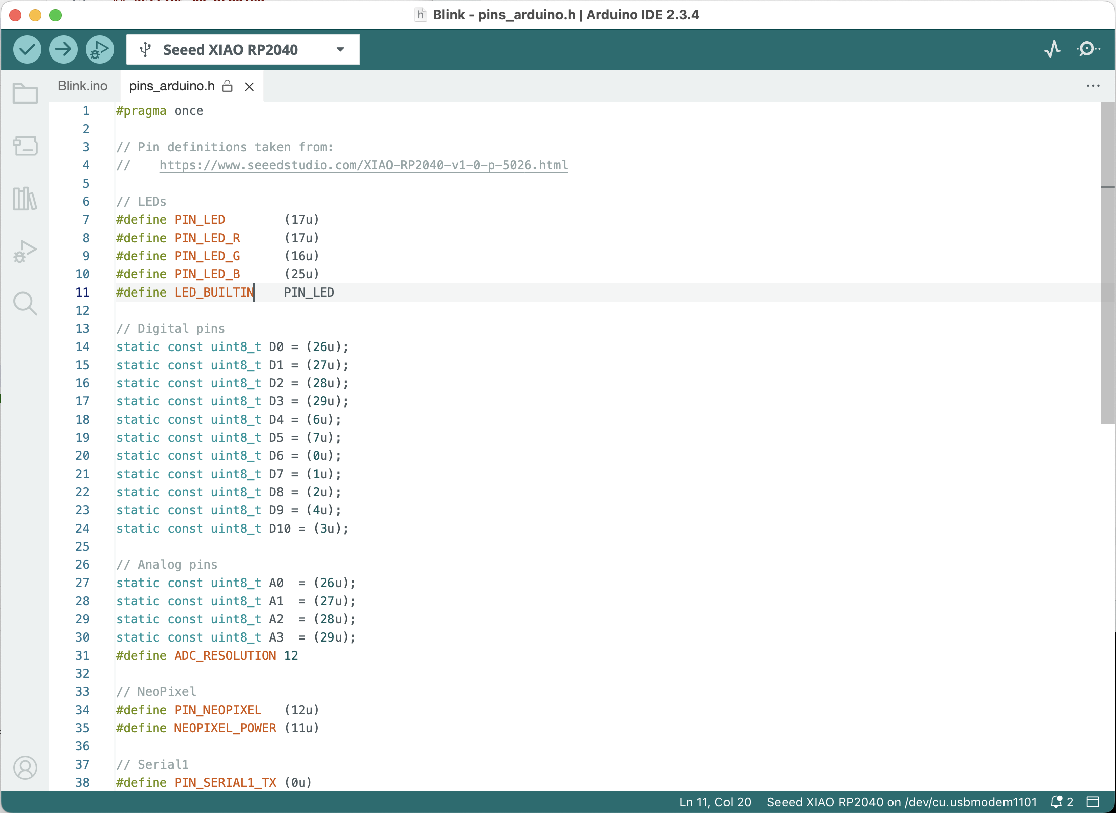
By holding Command (⌘) and clicking on LED_BUILTIN I was able to see where these constants are defined. For this board, LED_BUILTIN is defined as PIN_LED which is 17u. This is the same as PIN_LED_R which is a good hint on how to control the other colors, PIN_LED_G and PIN_LED_B.
v1 - Cycling LED colors
// These are reversed from the basic example
#define LED_OFF HIGH
#define LED_ON LOW

void setup() {
  // Initialize LED pins as output.
  pinMode(PIN_LED_R, OUTPUT);
  pinMode(PIN_LED_G, OUTPUT);
  pinMode(PIN_LED_B, OUTPUT);

  // Start by turning them off
  digitalWrite(PIN_LED_R, LED_OFF);
  digitalWrite(PIN_LED_G, LED_OFF);
  digitalWrite(PIN_LED_B, LED_OFF);
}

void loop() {
  digitalWrite(PIN_LED_R, LED_ON);   // turn the LED on by making the voltage LOW
  delay(1000);                       // wait for a second
  digitalWrite(PIN_LED_R, LED_OFF);  // turn the LED off
  delay(500);
  digitalWrite(PIN_LED_G, LED_ON);
  delay(1000);
  digitalWrite(PIN_LED_G, LED_OFF);
  delay(500);
  digitalWrite(PIN_LED_B, LED_ON);
  delay(1000);
  digitalWrite(PIN_LED_B, LED_OFF);
  delay(500);
}
To alternate colors correctly, I found two main changes. HIGH and LOW are reversed on this board when compared to the basic example. By defining them as LED_OFF and LED_ON, it makes the rest of the code easier to read. In the setup function, I turn the 3 colors off, so they start with a known state.
v2 - Non-blocking loop
From past experience, I know that my code with delay() in the main loop will prevent sensing button presses while the delay call is waiting. So I want to refactor my code to a non-blocking style. This is outlined in the Arduino examples under Examples > 02. Digital > BlinkWithoutDelay.
// These are reversed from the basic example
#define LED_OFF HIGH
#define LED_ON LOW

// state used to set the LED
int redState = LED_ON;
int greenState = LED_OFF;
int blueState = LED_OFF;

// will store last time LED was updated
unsigned long previousMillis = 0;

// interval at which to blink (milliseconds)
const long interval = 500;

void setup() {
  // Initialize LED pins as output.
  pinMode(PIN_LED_R, OUTPUT);
  pinMode(PIN_LED_G, OUTPUT);
  pinMode(PIN_LED_B, OUTPUT);

  // Start by turning them to their initial state
  digitalWrite(PIN_LED_R, redState);
  digitalWrite(PIN_LED_G, greenState);
  digitalWrite(PIN_LED_B, blueState);
}

void loop() {

  // check to see if it's time to change the LED
  unsigned long currentMillis = millis();

  if (currentMillis - previousMillis >= interval) {
    // save the last time you blinked the LED
    previousMillis = currentMillis;

    if (redState == LED_ON) {
      redState = LED_OFF;
      greenState = LED_ON;
      blueState = LED_OFF;
    } else if (greenState == LED_ON) {
      redState = LED_OFF;
      greenState = LED_OFF;
      blueState = LED_ON;
    } else if (blueState == LED_ON) {
      redState = LED_ON;
      greenState = LED_OFF;
      blueState = LED_OFF;
    }

    // Turn them off and on based on their new state
    digitalWrite(PIN_LED_R, redState);
    digitalWrite(PIN_LED_G, greenState);
    digitalWrite(PIN_LED_B, blueState);
  }
}
My version extends the example to make it support the RP2040's multiple LED colors.
v3 - Responding to a button press
// These are reversed from the basic example
#define LED_OFF HIGH
#define LED_ON LOW

// Button will be connected to pin 10 (and ground)
#define PIN_BUTTON D10
// Pull-up means that the button will go LOW when pressed
#define BUTTON_PRESSED LOW

// State used to set the LED
int redState = LED_ON;
int greenState = LED_OFF;
int blueState = LED_OFF;

// Will store last time LED was updated
unsigned long previousMillis = 0;

// interval at which to blink (milliseconds)
const long interval = 50;

void setup() {
  // Start serial connection
  // Serial.begin(9600);

  // Initialize LED pins as output.
  pinMode(PIN_LED_R, OUTPUT);
  pinMode(PIN_LED_G, OUTPUT);
  pinMode(PIN_LED_B, OUTPUT);

  // Button pin is set to "pull up"
  pinMode(PIN_BUTTON, INPUT_PULLUP);

  // Start by turning them to their initial state
  digitalWrite(PIN_LED_R, redState);
  digitalWrite(PIN_LED_G, greenState);
  digitalWrite(PIN_LED_B, blueState);
}

void loop() {

  // Read button pin
  int sensorVal = digitalRead(PIN_BUTTON);

  // Serial.println(sensorVal);

  // If button is pressed
  if (sensorVal == BUTTON_PRESSED) {

    unsigned long currentMillis = millis();

    if (currentMillis - previousMillis >= interval) {
      previousMillis = currentMillis;

      // Cycle the colors
      if (redState == LED_ON) {
        redState = LED_OFF;
        greenState = LED_ON;
        blueState = LED_OFF;
      } else if (greenState == LED_ON) {
        redState = LED_OFF;
        greenState = LED_OFF;
        blueState = LED_ON;
      } else if (blueState == LED_ON) {
        redState = LED_ON;
        greenState = LED_OFF;
        blueState = LED_OFF;
      }

      // Turn them off and on based on their new state
      digitalWrite(PIN_LED_R, redState);
      digitalWrite(PIN_LED_G, greenState);
      digitalWrite(PIN_LED_B, blueState);
    }
  }
}
⚠️ I lost some time because I thought that my button was connected to pin 10, but
D10is actually(3u). I should have followed my own advice and paid more attention to pins_arduino.h.
It's a game! Press the button and try to let go on a certain color. I could extend this by experimenting with LED color mixing, to make more than 3 colors.
It also might be more practical to debounce the button press, and do one state change per button press.
Soldering basics
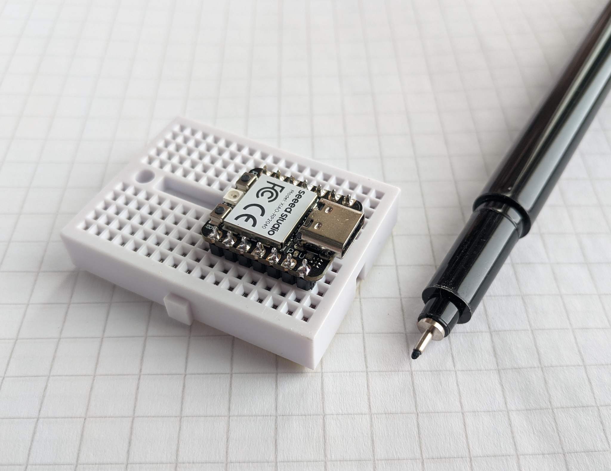
To make it easier to test the RP2040, I soldered on header pins. Apparently there is some contention between Fab Academy instructors if header pins should be used, but I like that I'll be able to test things with the breadboard now, and potentially reuse the same chip in later designs.
Conclusion
I'm attracted to the lowest spec microcontrollers. Less power means longer battery life and less heat to deal with. On the other hand, it's nice to be able to get started with the RP2040 with a single USB cable.
I'm comfortable with C-style languages because of my experience with JavaScript. The Arduino IDE and RP2040 make it easy to focus on the programming.
Though it's a fun constraint, I'm looking forward to making something more interactive than this single-button single-pixel game.