Week 11
Input Devices
Brief Overview
For this assignment, I have documented my learning experiences with input devices, including their types, working principles, and how to connect them to various microcontroller boards, including the one I built this week. I have detailed my use of my custom board with both input and output devices relevant to my final project. This week, I successfully troubleshooted and programmed my board. I connected sensors for temperature, humidity, and methane gas detection. Additionally, I have recorded what went well, what didn't, how I would approach things differently in future assignments, and my learning outcomes.
My Heroshot for this Week
 |
 |
 |
 |
Introduction to Input Devices:
Definition:
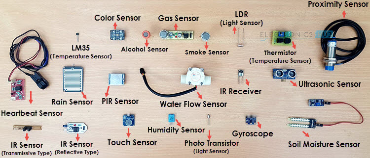
An input device is a hardware component used to provide data and control signals to a computer or other electronic system. These devices allow users to interact with and control the system by inputting information, commands, or actions. Examples of input devices include keyboards, mice, sensors, touchscreens, and microphones. Input devices can capture various types of data, such as text, images, sound, temperature, and motion, enabling the system to process and respond to the user's inputs.
Purpose
The purpose of input devices is to facilitate interaction between the user and a computer or electronic system. They serve several key functions:
- Data Entry: Input devices allow users to enter data into the system, such as text, numbers, and commands.
- Control: They enable users to control the operation and behavior of the system, such as navigating interfaces, executing programs, and manipulating objects.
- Feedback: Input devices provide a means for users to give real-time feedback to the system, which can be used to adjust processes or outputs.
- Automation: They can automate data collection by capturing information from the environment, such as sensors measuring temperature, humidity, or motion, and sending this data to the system for processing.
- Enhancing User Experience: By offering intuitive and responsive ways to interact with the system, input devices improve the overall user experience, making technology more accessible and efficient to use.
Making a Board for Input Device
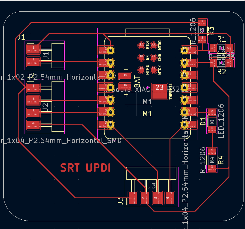
So I have designed and milled a UPDI Board for this Assignment
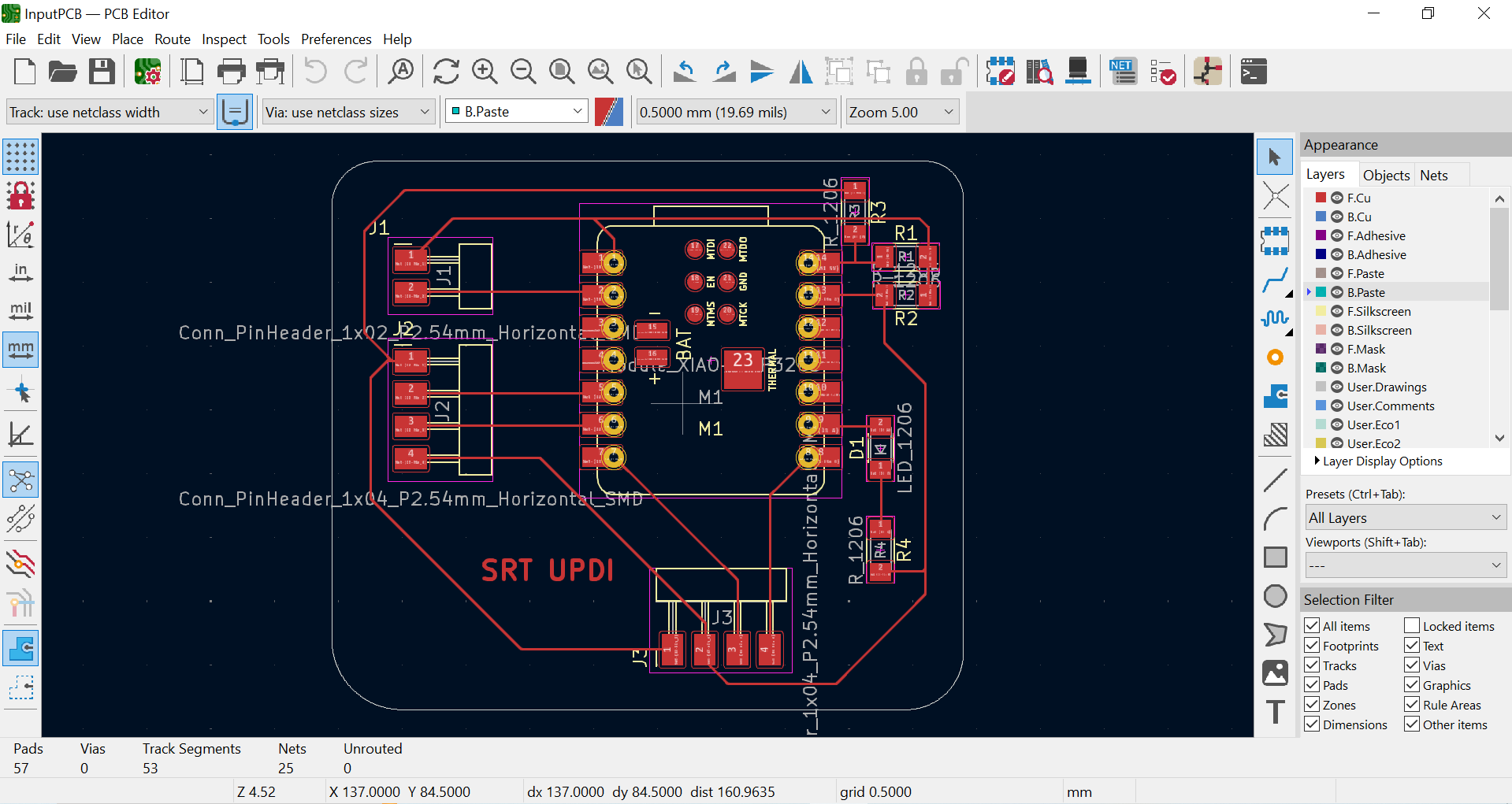
Making a Schematic and Routing the connection on KiCAD
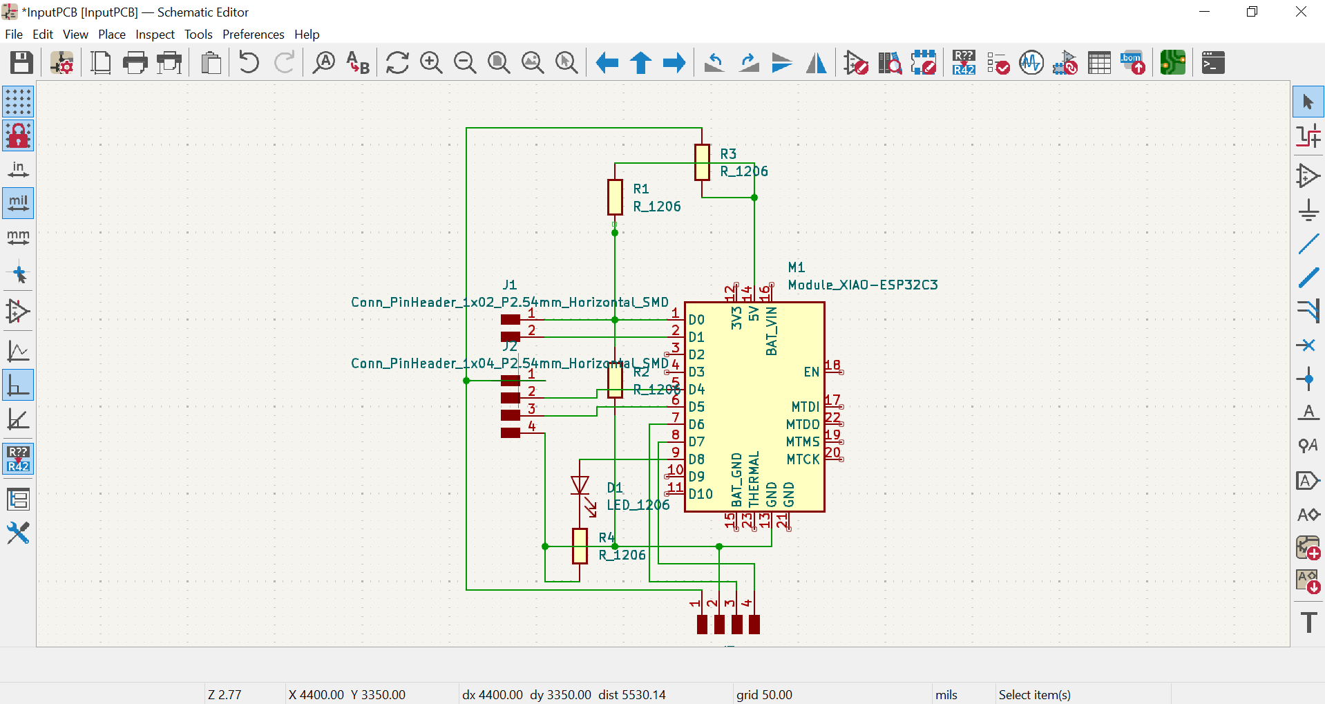
Making a Schematic and Routing the connection on KiCAD

Final Board is ready to Mill
To see the board milling process you can refre my Electronics week production assignment here
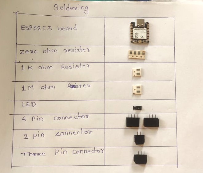
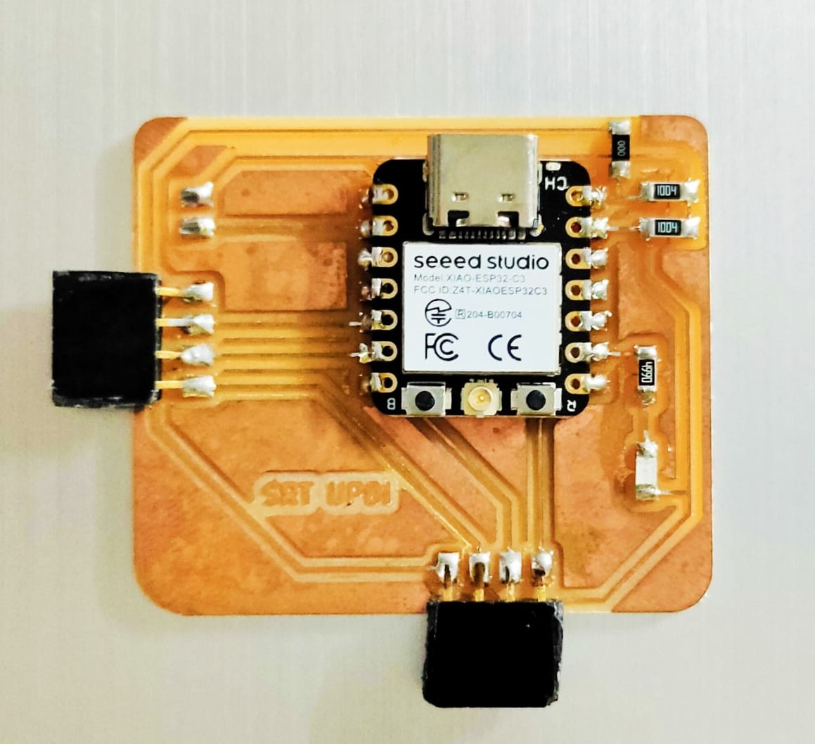
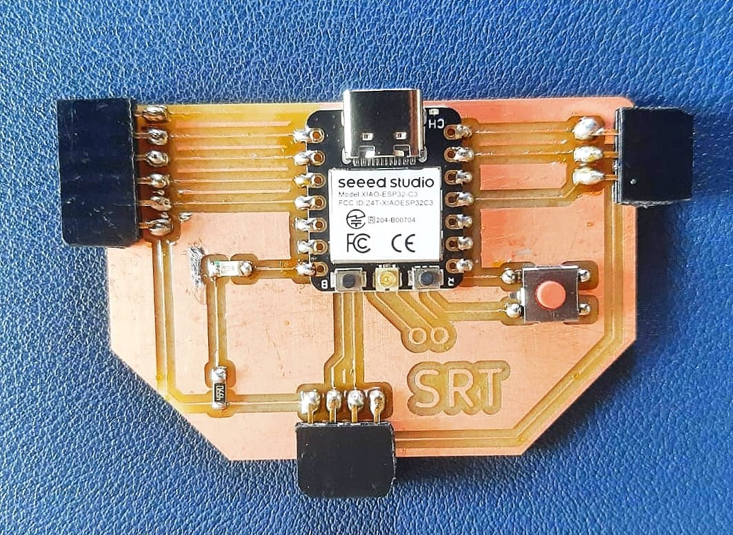
Soldering and Stuffing board
|
|
Input Devices in my assignment
Ultrasonic Sensor:-
Definition
An ultrasonic sensor is a device that measures distance by using ultrasonic waves. It works by emitting a high-frequency sound wave (ultrasound) and then measuring the time it takes for the echo of the sound wave to return after bouncing off an object. This time delay is used to calculate the distance between the sensor and the object.
Working Principle
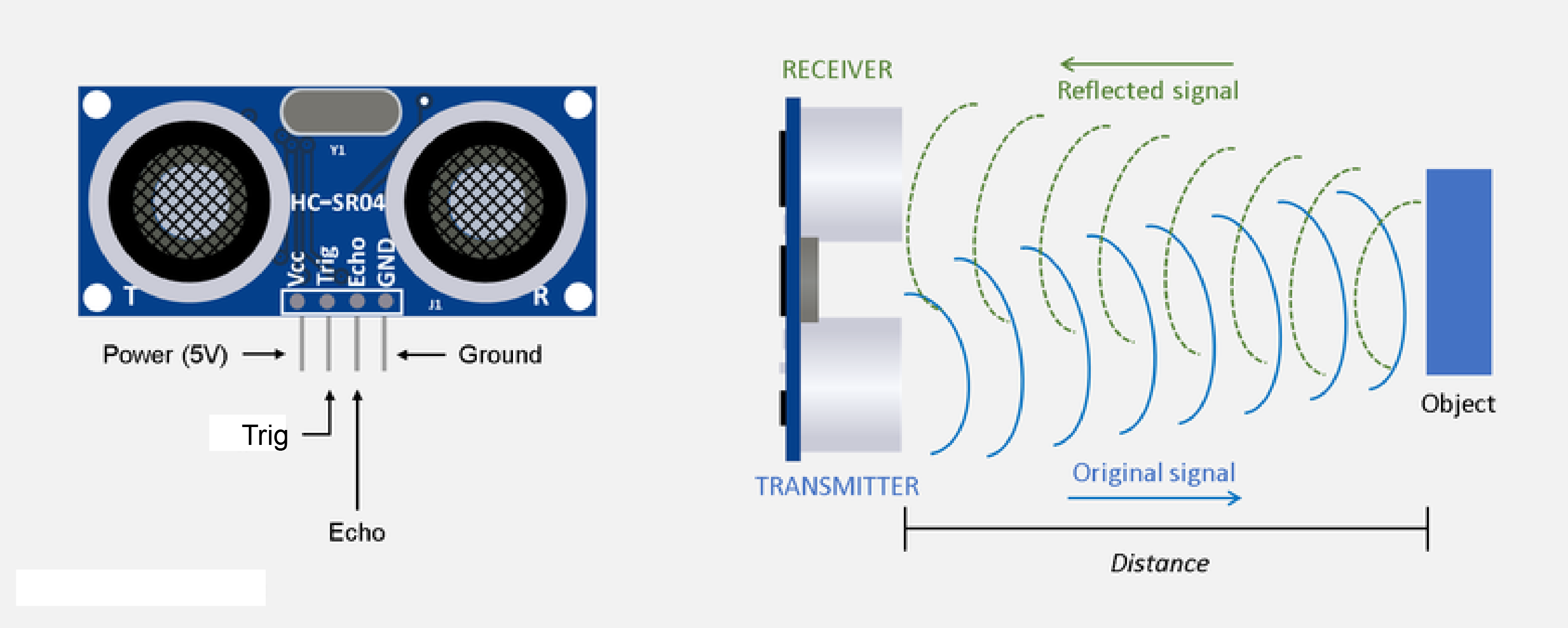
The ultrasonic sensor typically consists of two main components: a transmitter and a receiver. The transmitter emits the ultrasonic sound waves, while the receiver detects the reflected waves. The basic working steps are as follows:
- The transmitter emits a burst of ultrasonic sound waves.
- The sound waves travel through the air and hit an object.
- The waves are reflected back towards the sensor.
- The receiver detects the reflected waves.
- The sensor calculates the time interval between sending and receiving the waves to determine the distance.
Applications
Ultrasonic sensors are used in a variety of applications, including:
- Distance Measurement: Measuring the distance to an object in various industrial and automotive applications.
- Obstacle Detection: Detecting obstacles in robotics and autonomous vehicles.
- Level Sensing: Monitoring the level of liquids or solids in tanks and silos.
- Proximity Sensing: Detecting the presence of an object in close proximity, used in security systems and automatic doors.
- Object Counting: Counting objects on a conveyor belt in manufacturing processes.
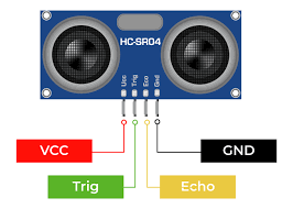
Ultrasonic Sensor Pinout Diagram:
The pinout diagram for an ultrasonic sensor typically includes connections for power, ground, and signal pins for both transmitting and receiving ultrasonic waves.
Commonly found pins in an ultrasonic sensor pinout diagram may include:
- VCC: This pin is used to supply power to the ultrasonic sensor. It typically requires a voltage within a specified range, such as 5V.
- GND: This pin is the ground connection for the ultrasonic sensor, providing the reference voltage for the circuit.
- Trig (Trigger): This pin is used to send a pulse signal from the microcontroller to initiate the ultrasonic burst. The sensor sends out an ultrasonic wave when this pin is triggered.
- Echo: This pin is used to receive the reflected ultrasonic wave. The sensor outputs a pulse signal to the microcontroller, indicating the time taken for the wave to return after hitting an object.
The pinout diagram provides a visual representation of these connections, aiding in the integration of the ultrasonic sensor into electronic projects or systems.
Now lets connect the Ultrasonic Sensor with Board to Collect Data
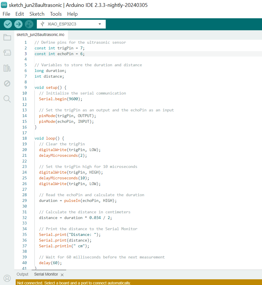
Uploading Code
Testing and Data collection on Serial Monitor
Code Explanation
Setup:
Serial.begin(9600); initializes serial communication at a baud rate of 9600.
pinMode(trigPin, OUTPUT); sets the trigger pin (pin 7) as an output.
pinMode(echoPin, INPUT); sets the echo pin (pin 6) as an input.
Loop:
Clears the trigger pin.
Sets the trigger pin high for 10 microseconds to send out an ultrasonic pulse.
Reads the duration of the pulse reflected back to the echo pin.
Calculates the distance based on the duration.
Prints the distance to the Serial Monitor.
IR Sensor:-
Definition
An IR (Infrared) sensor is a device that detects infrared radiation in order to sense its surroundings. These sensors can be used to measure the heat emitted by objects and to detect motion. They work by emitting infrared light and then measuring the reflection or absorption of this light by objects in their vicinity.
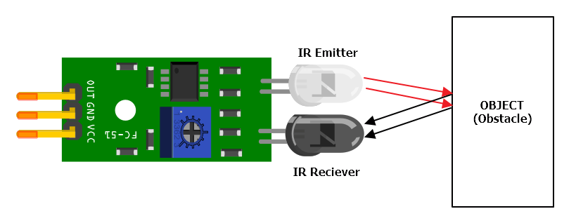
Working Principle
An IR sensor typically consists of two main components: an infrared LED (Light Emitting Diode) and an IR photodiode or phototransistor. The basic working steps are as follows:
- The IR LED emits infrared light.
- The emitted infrared light travels through the air and hits an object.
- The light is either reflected back to the sensor or absorbed by the object.
- The IR photodiode or phototransistor detects the reflected infrared light.
- The sensor measures the intensity of the reflected light to determine the presence and distance of the object.
Applications
IR sensors are used in a variety of applications, including:
- Proximity Detection: Detecting the presence of objects in close proximity, used in touchless interfaces and automatic doors.
- Motion Detection: Detecting movement in security systems and automatic lighting controls.
- Line Following: Guiding robots to follow a path marked by a line, commonly used in robotic competitions.
- Remote Controls: Sending signals to electronic devices such as TVs and air conditioners.
- Temperature Sensing: Measuring the temperature of objects without direct contact, used in thermal imaging cameras.
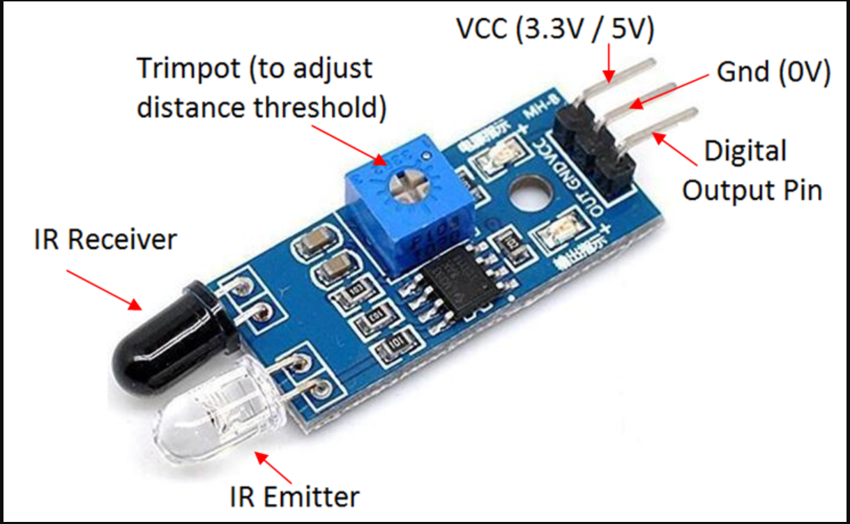
IR Sensor Pinout Diagram:
The pinout diagram for an IR sensor typically includes connections for power, ground, and signal pins for both the IR LED and the photodiode or phototransistor.
Commonly found pins in an IR sensor pinout diagram may include:
- VCC: This pin is used to supply power to the IR sensor. It typically requires a voltage within a specified range, such as 5V.
- GND: This pin is the ground connection for the IR sensor, providing the reference voltage for the circuit.
- OUT (Output): This pin outputs a signal to the microcontroller indicating the detection of infrared light. The signal can vary depending on the presence and intensity of the reflected IR light.
The pinout diagram provides a visual representation of these connections, aiding in the integration of the IR sensor into electronic projects or systems.
Testing and Data collection on Serial Monitor
Code Explanation
Setup:
Serial.begin(9600); initializes serial communication at a baud rate of 9600.
pinMode(irPin, INPUT); sets the IR sensor signal pin (GPIO 21) as an input.
Loop:
Reads the value from the IR sensor.
Checks if the sensor is detecting an obstacle.
Prints "Obstacle detected" if an obstacle is detected (when the IR sensor signal pin reads HIGH).
Prints "No obstacle" if no obstacle is detected (when the IR sensor signal pin reads LOW).
Waits for 100 milliseconds before taking the next reading.