
Output devices
individual assignment:
- add an output device to a microcontroller board you've designed,
- and program it to do something
group assignment:
- measure the power consumption of an output device
group
assignment
Plan: Figure out how to connect my Neopixelstick to the
pcb board fromlast week
Link to my board
OUTPUTS:
- NeoPixel (meant to represent lava)
- Vibration motor (earthquake before eruption)
I began by soldering a NeoPixel stick 8x 505 RBG LED to a female componement and connected the wires to my MF-Xiao Board.
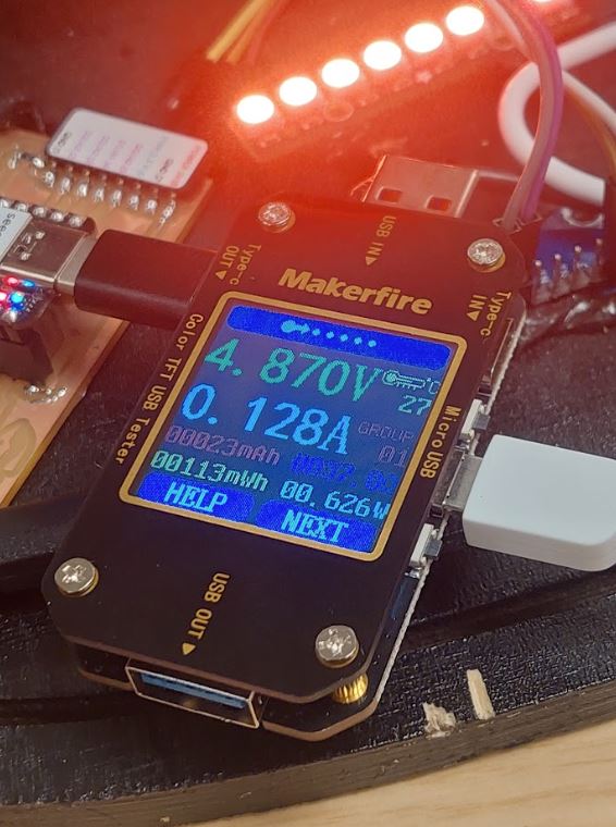
I used a N10 Multifunctional Tester by Makerfire to test the power usage (examples can be seen in videos further down below)
I used chat gpt and github copilot to help me figure out a code that would light up the strip in different colours. The aim was to use colours that resemble lava

The neopixelstrip turned out to be way brighter than I ever hoped! Example:
I used a 3d print i found in the lab as a shell, both to test the colours and also to shield my eyes (the brightness is meant to be bright thats why I decided not to turn it down)
more talking
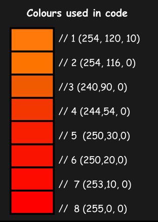
I used chat gpt to generate a code for me that would switch between colours. I then manually picked out colours while testing them through the Neopixels.
Originally I had a pallette ready on Inkscape but the colours did not show up the same on the light as they did on my screen so thats why I handpicked them.
https://chatgpt.com/share/fb0fe315-b56e-4796-bdbc-63ab132304c9
Down below you can find the code I used!
Code I used:
#include <Adafruit_NeoPixel.h>

#define PIN A0
#define NUM_PIXELS 8

Adafruit_NeoPixel pixels(NUM_PIXELS, PIN, NEO_GRB + NEO_KHZ800);

void setup() {
 pixels.begin();
 pixels.show(); // Initialize all pixels to off
}

void loop() {


 // 1 Set all pixels to light yellow
 for (int i = 0; i < NUM_PIXELS; i++) {
 pixels.setPixelColor(i, pixels.Color(254, 120, 10));
 }
 pixels.show();
 delay(1000);

 // 2Set all pixels to green
 for (int i = 0; i < NUM_PIXELS; i++) {
 pixels.setPixelColor(i, pixels.Color(254, 116, 0));
 }
 pixels.show();
 delay(1000);


 //3 Set all pixels to blue
 for (int i = 0; i < NUM_PIXELS; i++) {
 pixels.setPixelColor(i, pixels.Color(240,90, 0));
 }
 pixels.show();
 delay(1000);


 // 4 Set all pixels to blue
 for (int i = 0; i < NUM_PIXELS; i++) {
 pixels.setPixelColor(i, pixels.Color(244,54, 0));
 }
 pixels.show();
 delay(1000);


 // 5 Set all pixels to orange
 for (int i = 0; i < NUM_PIXELS; i++) {
 pixels.setPixelColor(i, pixels.Color(250,30,0));
 }
 pixels.show();
 delay(1000);
 // 6 Set all pixels to orange
 for (int i = 0; i < NUM_PIXELS; i++) {
 pixels.setPixelColor(i, pixels.Color(250,20,0));
 }
 pixels.show();
 delay(1000);

 // 7 Set all pixels to SUPER RED
 for (int i = 0; i < NUM_PIXELS; i++) {
 pixels.setPixelColor(i, pixels.Color(253,10, 0));
 }
 pixels.show();
 delay(1000);

 // 8 Set all pixels to SUPER RED
 for (int i = 0; i < NUM_PIXELS; i++) {
 pixels.setPixelColor(i, pixels.Color(255,0, 0));
 }
 pixels.show();
 delay(1000);
}
Another code
Here is another code i generated. This one has a smoother transition between the colours.Video preview:
power use: 4.85V and 0.161A
#include <Adafruit_NeoPixel.h>


// Define the pin where the NeoPixel strip is connected
#define PIN A0


// Define the number of NeoPixels
#define NUMPIXELS 8


// Create the NeoPixel object
Adafruit_NeoPixel pixels(NUMPIXELS, PIN, NEO_GRB + NEO_KHZ800);


// Define the colors
uint32_t colors[] = {
  pixels.Color(254, 120, 10),  // Color 1
  pixels.Color(254, 116, 0),   // Color 2
  pixels.Color(240, 90, 0),    // Color 3
  pixels.Color(244, 54, 0),    // Color 4
  pixels.Color(250, 30, 0),    // Color 5
  pixels.Color(250, 20, 0),    // Color 6
  pixels.Color(253, 10, 0),    // Color 7
  pixels.Color(255, 0, 0)      // Color 8
};


// Function to interpolate between colors
uint32_t interpolateColor(uint32_t color1, uint32_t color2, float fraction) {
  uint8_t r1 = (color1 >> 16) & 0xFF;
  uint8_t g1 = (color1 >> 8) & 0xFF;
  uint8_t b1 = color1 & 0xFF;

  uint8_t r2 = (color2 >> 16) & 0xFF;
  uint8_t g2 = (color2 >> 8) & 0xFF;
  uint8_t b2 = color2 & 0xFF;

  uint8_t r = r1 + (r2 - r1) * fraction;
  uint8_t g = g1 + (g2 - g1) * fraction;
  uint8_t b = b1 + (b2 - b1) * fraction;

  return pixels.Color(r, g, b);
}


void setup() {
  // Initialize the NeoPixel library
  pixels.begin();
  // Clear all pixels
  pixels.show();
}


void loop() {
  // Loop through each color
  for (int colorIndex = 0; colorIndex < sizeof(colors) / sizeof(colors[0]); colorIndex++) {
    // Get the current color and the next color
    uint32_t currentColor = colors[colorIndex];
    uint32_t nextColor = colors[(colorIndex + 1) % (sizeof(colors) / sizeof(colors[0]))];

    // Transition smoothly from currentColor to nextColor
    for (int step = 0; step <= 100; step++) {
      float fraction = step / 100.0;
      uint32_t blendedColor = interpolateColor(currentColor, nextColor, fraction);

      // Set all pixels to the blendedColor
      for (int i = 0; i < NUMPIXELS; i++) {
        pixels.setPixelColor(i, blendedColor);
      }
      pixels.show();
      delay(10);  // Wait 10 milliseconds to create a smooth transition
    }


    // Light up each pixel one by one with the next color
    for (int i = 0; i < NUMPIXELS; i++) {
      pixels.setPixelColor(i, nextColor);
      pixels.show();
      delay(50);  // Wait 50 milliseconds to light up each pixel one by one
    }
  }
}
Vibration motor
I also used a vibration motor for this
week.
Its an electric motor equipped with an
unbalanced mass that generates vibrations when
powered.
The vibration motor's purpose is to mimic an
earthquake that often occur moments before an eruption
The vibration motor will start when it gets signal
from the microcontroller and it will be turned on for
2.000 milliseconds before the lava flow starts.
The power usage and the motor in
action can be seen in the video below :D
(it was 4.93V and 0.054A)
IMPORTANT SIDE NOTE: My global evaluator pointed out
that for the vibration motor, the Back EMF can destroy
the controller. So it’s better to drive it not
directly from the microcontroller pins. He
suggested I use a transistor and for the future I will
be looking into it. So if anyone wants to recreate
this its best to look into that.
Vibration motor code
// Define pin numbers
const int buttonPin = D7;   // Pin for the button
const int ledPin = D6;      // Pin for the LED
const int motorPin = D10;   // Pin for the vibration motor

// Variable to store the button state
int buttonState = 0;

void setup() {
  // Initialize the button pin as an input with internal pull-up resistor
  pinMode(buttonPin, INPUT_PULLUP);

  // Initialize the LED pin as an output
  pinMode(ledPin, OUTPUT);

  // Initialize the vibration motor pin as an output
  pinMode(motorPin, OUTPUT);

  // Start with the LED and motor turned off
  digitalWrite(ledPin, LOW);
  digitalWrite(motorPin, LOW);
}

void loop() {
  // Read the state of the button
  buttonState = digitalRead(buttonPin);

  // Check if the button is pressed
  if (buttonState == HIGH) {
    // Turn on the LED
    digitalWrite(ledPin, HIGH);

    // Turn on the vibration motor
    digitalWrite(motorPin, HIGH);
  } else {
    // Turn off the LED
    digitalWrite(ledPin, LOW);

    // Turn off the vibration motor
    digitalWrite(motorPin, LOW);
  }
}
Links
Chat GPTArduino