WEEK 6 - Embedded Programming
Checklist:
- Write a program for a microcontroller development board to interact (with local input &/or output devices) and communicate (with remote wired or wireless devices).
Group assignment

Group apport
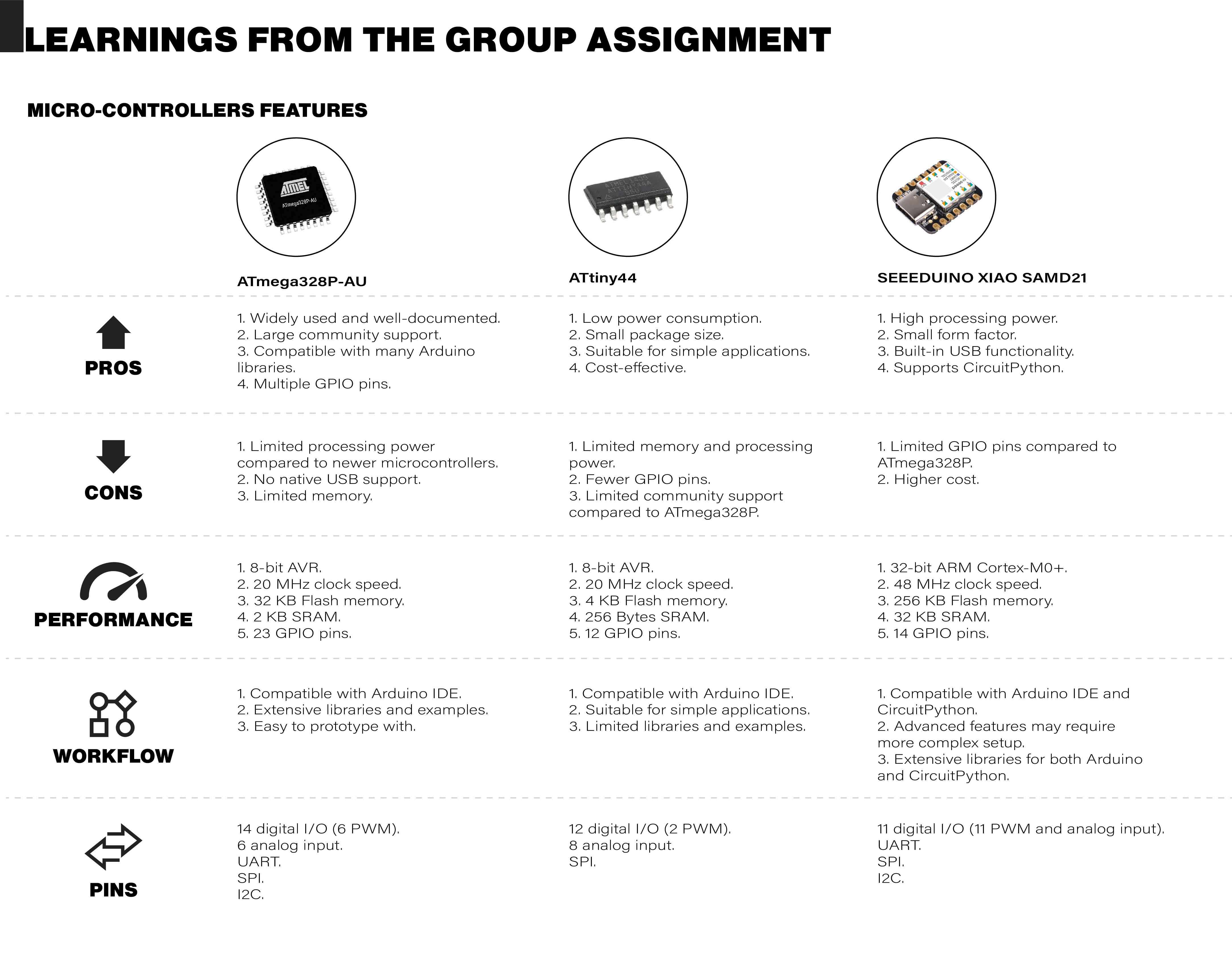
My contribution to the group involved researching the Atmega328P-AU, identifying its advantages, disadvantages, and key features. Additionally, I mapped out the programming pins and outlined the workflow from the software perspective.
Connections Diagram
To begin programming, it was necessary to determine which LEDs were connected to which pins of the Seeeduino. To achieve this, I created a diagram to help identify these pins and communication ports.

Code development
Explanation
Variable Declarations:
buttonPinis assigned to analog pin A1.ledPinis assigned to analog pin A0.buttonStateis a variable used to store the state of the button.
Setup Function:
pinMode(ledPin, OUTPUT);sets pin A0 as an output, which will control an LED.pinMode(6, OUTPUT);sets digital pin 6 as an output.pinMode(7, OUTPUT);sets digital pin 7 as an output.pinMode(buttonPin, INPUT);sets pin A1 as an input to read the button state.
Loop Function:
buttonState = digitalRead(buttonPin);reads the current state of the button (either HIGH if pressed or LOW if not pressed).if (buttonState == HIGH)checks if the button is pressed.- If the button is pressed,
digitalWrite(ledPin, HIGH);turns on the LED connected to A0. - If the button is not pressed,
digitalWrite(ledPin, LOW);turns off the LED connected to A0. digitalWrite(6, HIGH);anddigitalWrite(7, HIGH);turn on the LEDs connected to pins 6 and 7.delay(1000);waits for 1 second.digitalWrite(6, LOW);anddigitalWrite(7, LOW);turn off the LEDs connected to pins 6 and 7.delay(1000);waits for another 1 second.
What Should Happen
- When the button connected to A1 is pressed, the LED connected to A0 will turn on. When the button is not pressed, the LED will turn off.
- Independently of the button state, the LEDs connected to pins 6 and 7 will blink on and off every second.

Programming and Result
Board Installation Guide
First, you need to install the board. I obtained the necessary information from the Seeed Studio website. The initial step is to add a web address in the Arduino software preferences to install the XIAO SAMD21 board. After this, connect the board, select the appropriate COM port, and upload the code.
Steps to Install the XIAO SAMD21 Board
- Open the Arduino software and go to File > Preferences.
- In the Additional Boards Manager URLs field, add the URL provided by Seeed Studio.
- Click OK to save the changes.
- Go to Tools > Board > Boards Manager and search for "XIAO SAMD21".
- Install the board package.
- Connect the XIAO SAMD21 board to your computer using a USB cable.
- In the Arduino software, go to Tools > Port and select the correct COM port for your board.
- Write or open your code in the Arduino IDE and click the Upload button to upload the code to the board.

Test Code
const int buttonPin = A1;
const int ledPin =  A0;
int buttonState = 0;         // variable for reading the pushbutton status

void setup() {
   pinMode(ledPin, OUTPUT);
   pinMode(6, OUTPUT);
   pinMode(7, OUTPUT);
   pinMode(buttonPin, INPUT);
}

void loop() {
  buttonState = digitalRead(buttonPin);
  if (buttonState == HIGH) {
    // turn LED on:
    digitalWrite(ledPin, HIGH);
  } else {
    // turn LED off:
    digitalWrite(ledPin, LOW);
  }
  digitalWrite(6, HIGH);
  digitalWrite(7, HIGH);
  delay(1000);
  digitalWrite(6, LOW);
  digitalWrite(7, LOW);
  delay(1000);
}
Result
I programmed the LEDs connected to pins 6 and 7 to turn on and off every second, and the LED connected to pin A0 to turn on each time the push button is activated.
Download resources
Codes
- Test Code
Code I used to test the board.
- Test Code Random LEDs
Code I used to test the board and record the results video.
Vector files
- Modified PCB - PDF
Modified for making the paths thicker.
- Modified PCB - SVG
Modified for making the paths thicker.