WEEK 2 - Computer-Aided Design
Checklist
- Model raster, vector, 2D, 3D, render, animate, simulate... a possible final project.
- Post images and videos of the process.
Raster
Software 1: Krita
When exploring raster programs for your projects, it's essential to select the right tools. In my case, I decided to try out GIMP, Krita, and GraphicsMagick. Out of these options, Krita turned out to be the quickest to download and install, making it an attractive choice for immediate use.

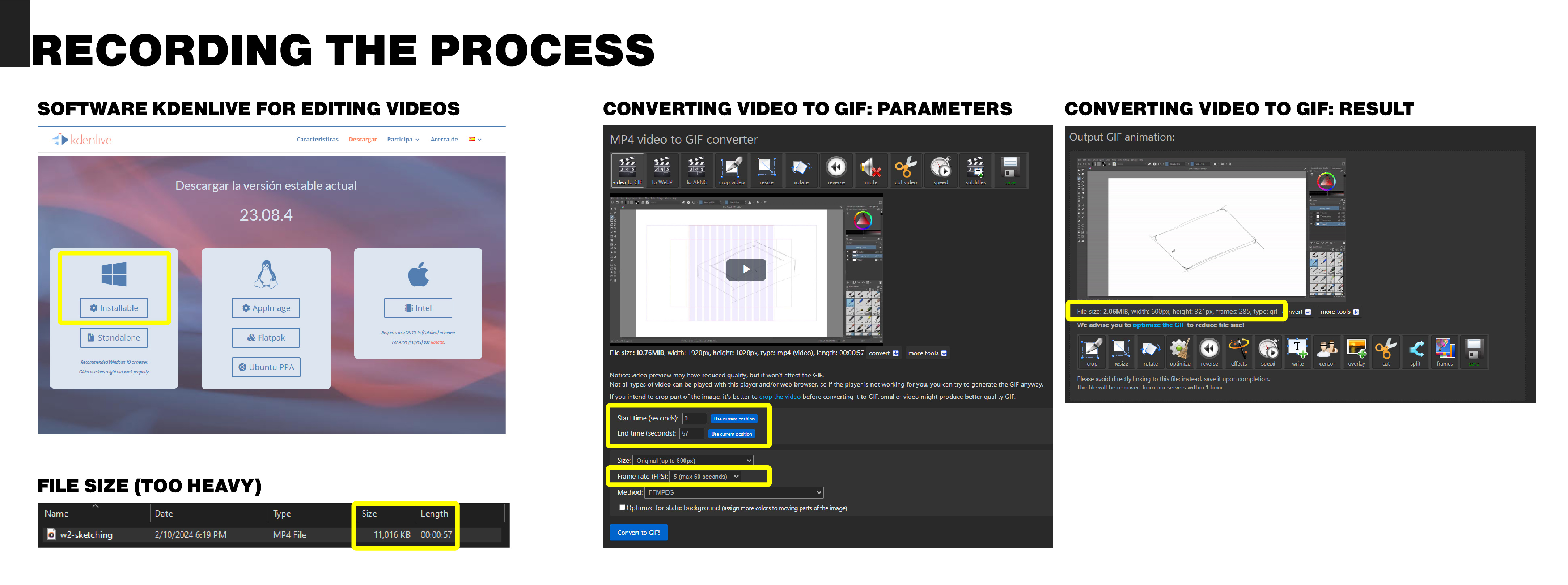
For recording my tutorial or project process, I utilized the built-in Windows screen recorder. You can access this feature by pressing Windows + Alt + R simultaneously. It's a handy tool for capturing on-screen actions efficiently. But it didn’t work as expected, so I’ll try another tool on next week's assignment.
After recording my demonstration, I needed to edit and refine the video before sharing it with others. For this task, I turned to Kdenlive, a versatile video editing software. You can download Kdenlive from their official website:
Video editing software: Kdenlive Download Link
To enhance my understanding of certain editing techniques, I watched instructional videos on YouTube. Specifically, I found tutorials on changing the video speed and exporting files particularly helpful.
Once my editing was complete, I faced the challenge of file size. The video was too large for easy sharing, so I decided to convert it into a GIF format. To accomplish this task, I used Ezgif, a user-friendly online tool for GIF conversion and optimization.
Video to gif website: Ezgif
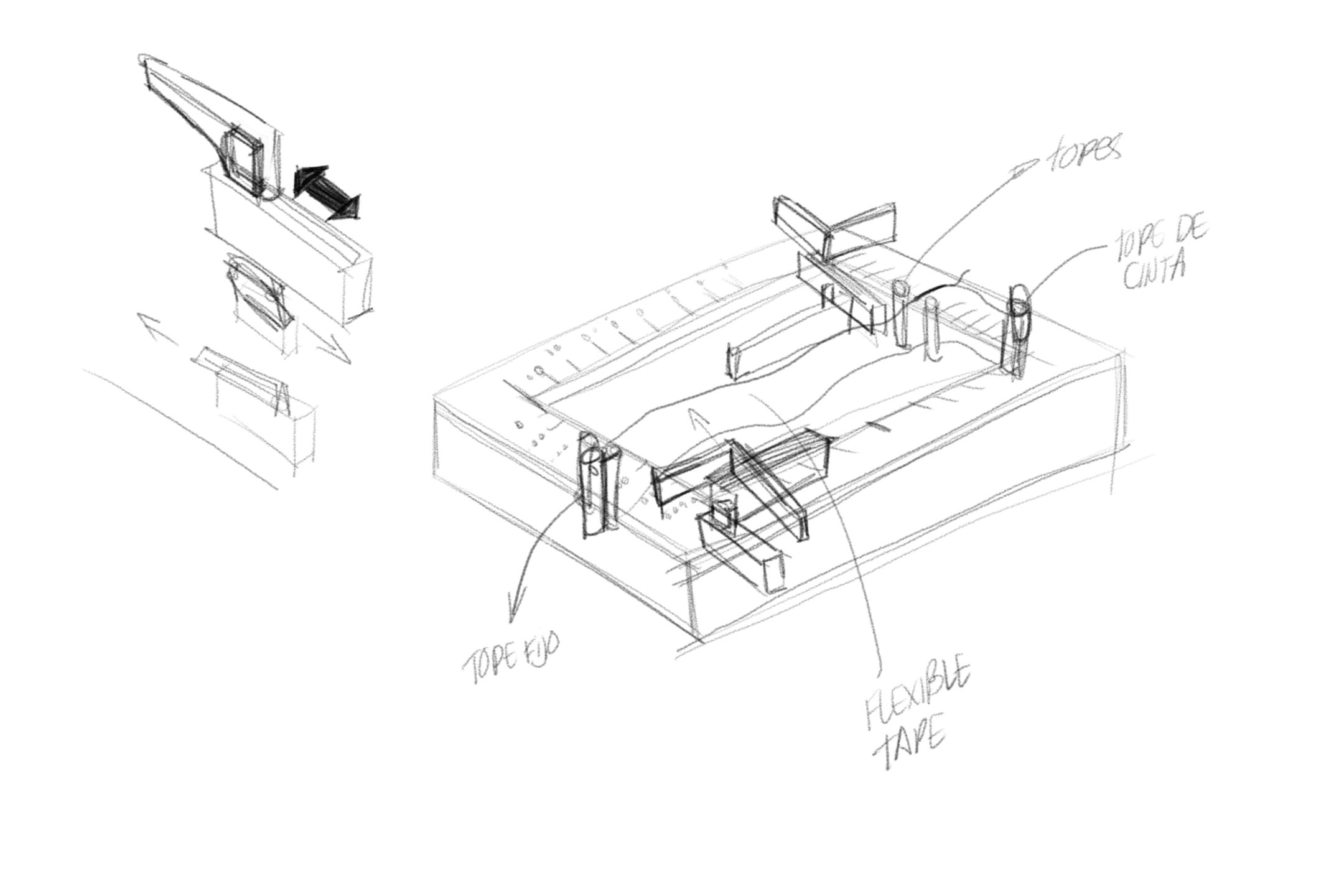
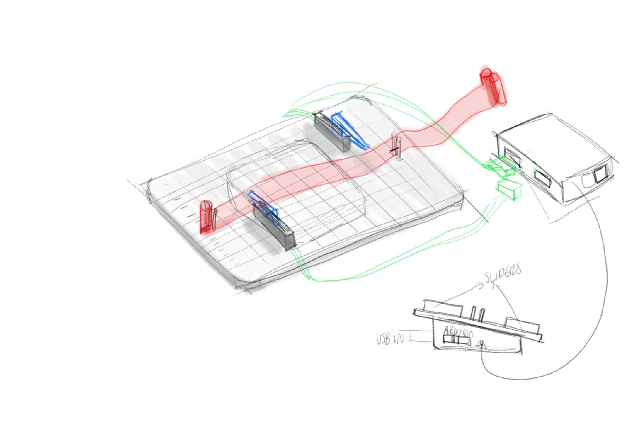
Sketch process

Sketch one
Sketch two
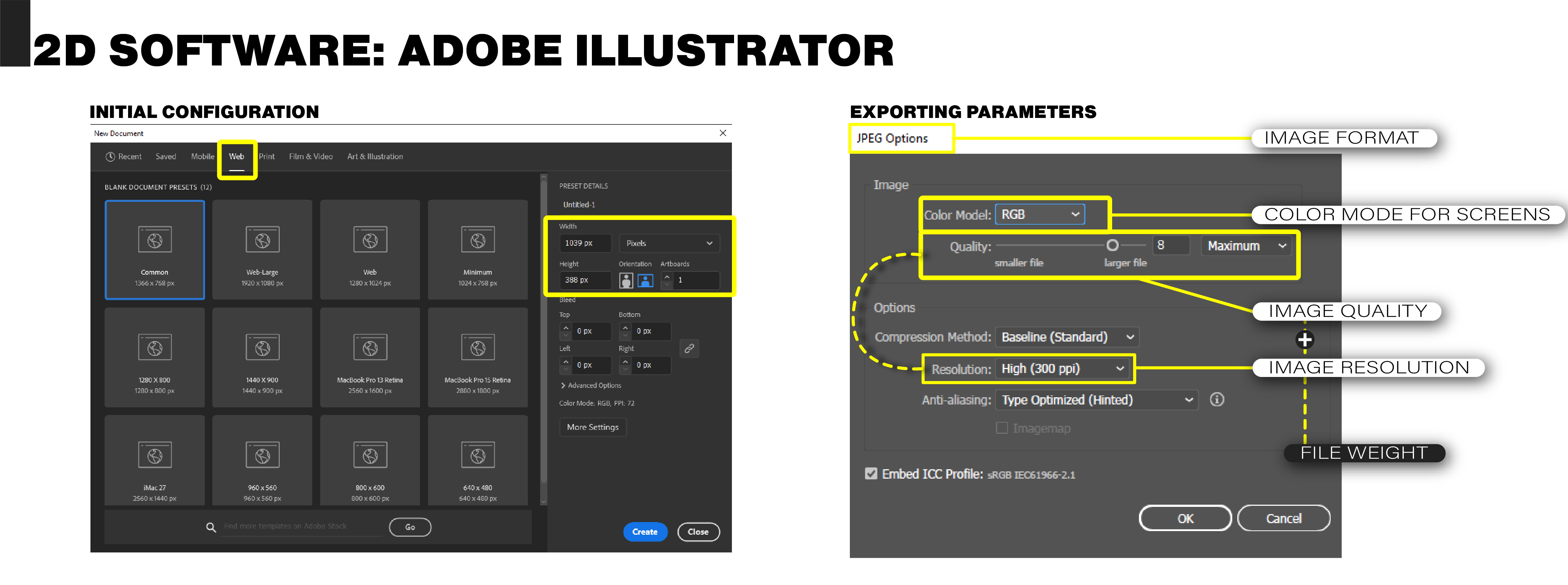
Software 2: Adobe Illustrator
For the development and editing of the images used to outline the content of my webpage, I chose to use Adobe Illustrator. I opted for this software because I am already familiar with it and because it allows me to work with large amounts of information without encountering any issues with its performance. Below is an example of the template model and size I use for the images, as well as the export parameters I employ to maintain image quality without taking up too much space.
CAD 1 - Autodesk Inventor Professional
To bring my sketch to life, I turned to Autodesk Inventor, a software I was already familiar with from previous projects. This allowed me to efficiently reuse some components for my current endeavor.
For the specific components I needed, such as linear potentiometers, I found suitable models on GrabCAD: Slide Potentiometer.
To keep everything organized, I created a dedicated project folder. This ensured all files were easily accessible as I worked on the modeling within the software. I named the project after the product I was designing: the Tactile Curve Drawing Device - TCDD.
To streamline the process of adding Braille numbers, I downloaded a specialized font from this source.
From there, I began modeling based on an assembly template, and below is an animation illustrating the process.
Render part 1 - Keyshot 10
After completing the sketch modeling, I proceeded with rendering using Keyshot 10, a software I've used before. This tool streamlines the process due to my existing resources, such as pre-set rendering environments. One such environment, originally created by "El Hilo Negro Studio" by Alberto Moreno (source), was particularly helpful.
I imported my STEP file to set up the scene and apply materials. However, I realized that for the concept to fully come across, I needed to create an example screenshot of how the curve created in the TCDD would appear in a digital environment. This required a pause in the rendering process to adjust the scene accordingly.
Following this adjustment, I proceeded with rendering, and below is an animation illustrating the initial rendering process, including scene setup and material application.

CAD 2 - Firefly
(Grasshopper-Rhinoceros)
To bridge the TCDD device from the physical realm to the digital space, I used Grasshopper, a component of Rhinoceros software. This allowed me to establish communication between the Arduino and potentiometers using the Firefly plugin. The Firefly plugin, developed by Jason Kelly Johnson and Andrew Payne (source), facilitated this integration process. Additionally, I used Arduino version 1.8.19 for the project.
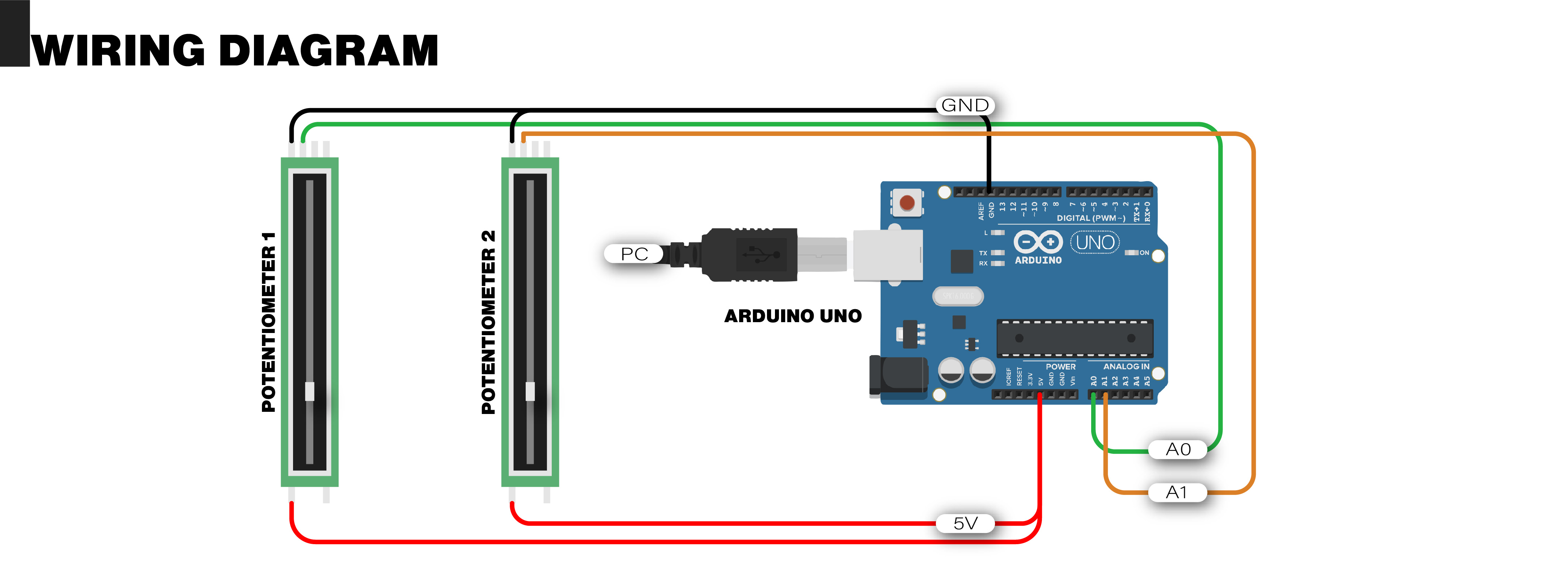
Initially, I connected the potentiometers to the Arduino board. Although the proposed design called for 50mm linear potentiometers, I utilized radial potentiometers available to me, which served the purpose effectively.
Wiring diagram
Uploading the code to the Arduino
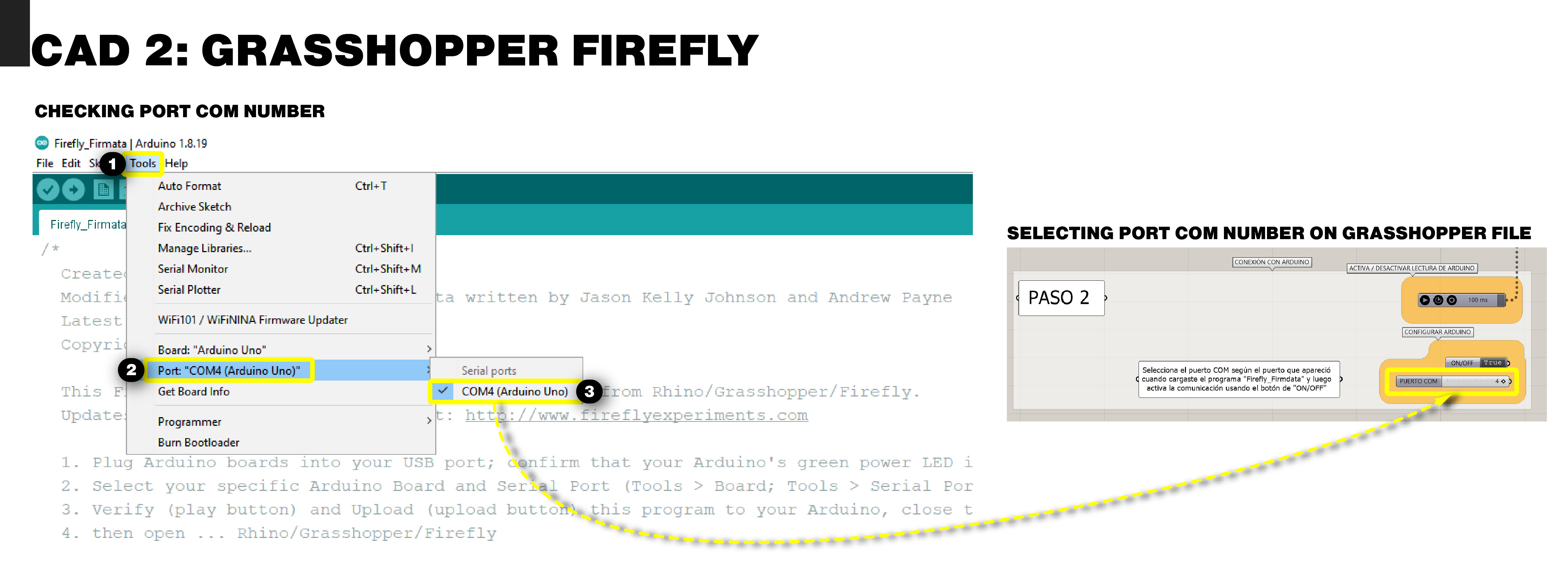
After making the connections, I uploaded the code from the "Firefly_Firmdata" file to my Arduino. I take this opportunity to check which COM port my Arduino is connected to (this will be useful when connecting the Arduino to the Grasshopper program).
Checking the port COM number
Editing the old grasshopper file
I had an old file that I used for a similar project, so I used that file as a base to modify the 3D modeling and display a curve with control points positioned in the same way as the potentiometers in the TCDD. Then, I organized the commands in the file to make it more understandable and highlighted the control points and steps to replicate this project. Below is a video summarizing the complete process. (After recording the video, I realized that the Microsoft app didn't record the Grasshopper editing part because it's a different window from Rhino 🙁, but I've included a screenshot of the final code.)

After confirming that the Arduino and the program are functioning correctly, I took a screenshot that will be useful for placing in the render.
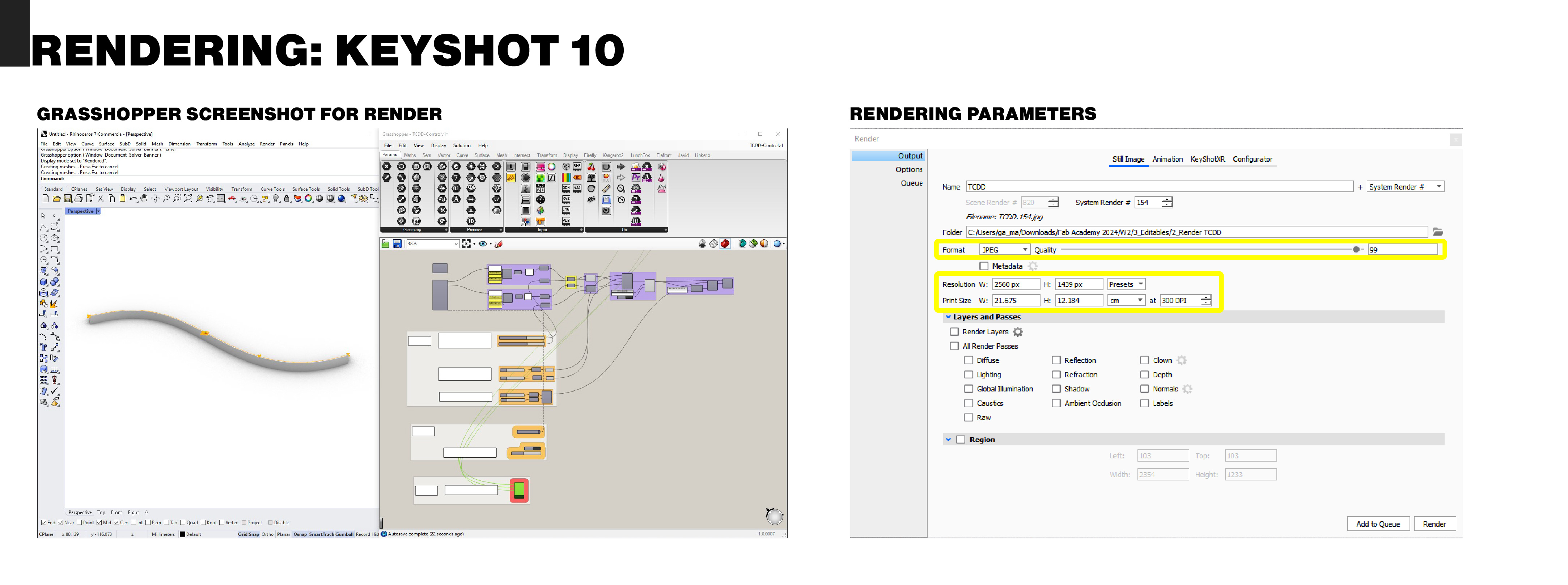
Render part 2 - Keyshot 10
For the second part of the rendering, I added the laptop from the Grabcad library as well and inserted the screenshot I took from the previous process. Then, I performed the rendering using the following parameters:
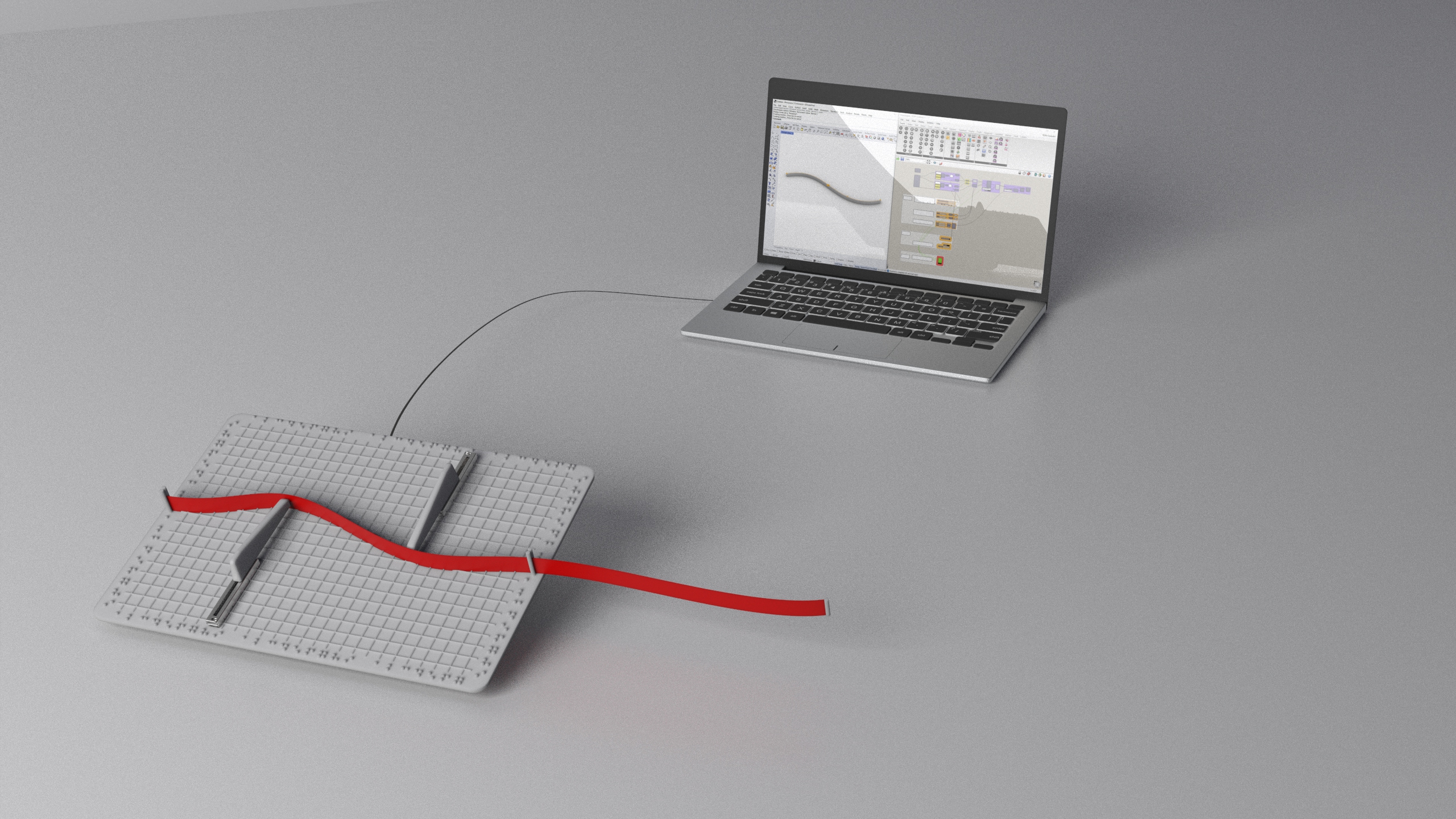
Render - Results
The one with the incorrect screenshot, because it didn’t match the 3d model curve:

The final one with matching curves on the laptop screen and the physical panel:
Download resources
2D Design
Resources for RASTER design
- Sketch Krita file
- Krita editable file used for the sketch.
- Sketch TIFF file
- File used for the sketch in TIFF format.
Resources for VECTOR design
- Web diagrams and images - Adobe Illustrator
- Editable file used to develop all the images and diagrams of the web.
- Web diagrams and images - PDF
- Editable file used to develop all the images and diagrams of the web.
3D Design
Resources for Autodesk Inventor
- Braille Font
- Font to change Arabic to Braille numerals.
- "TCDD" - CAD files - IPT
Editable Autodesk Inventor files (parts and assembly).
- "TCDD" - CAD files - STEP
Editable STEP files (parts and assembly).
- "TCDD" - CAD files - STL
STL files (parts and assembly).
Resources for Arduino
- Firefly-Firmdata
Code to communicate the Arduino board with Rhinoceros plug-in Firefly.
Resources for Rhinoceros
- Elefront421-Autobake / Firefly / Lunchbox
Installers of plug-ins and programs necessary to use the "TCDD" grasshopper editable file.
- "TCDD" grasshopper editable file
Rhinoceros (grasshopper) editable file.
Resources for Rendering (Keyshot)
- Render resources
STEP files (TCDD and laptop), image for laptop screen label and Keyshot rendering file (.bip).