WEEK 12 - Input Devices
Checklist:
- Measure something: add a sensor to a microcontroller board that you have designed and read it.
Learnings from the group assignment
The objective of the group assignment was to probe the analog levels and digital signals of an input device(s), which helped us distinguish between an analog and a digital signal.

Programming and design process and Results
Connections before the programming
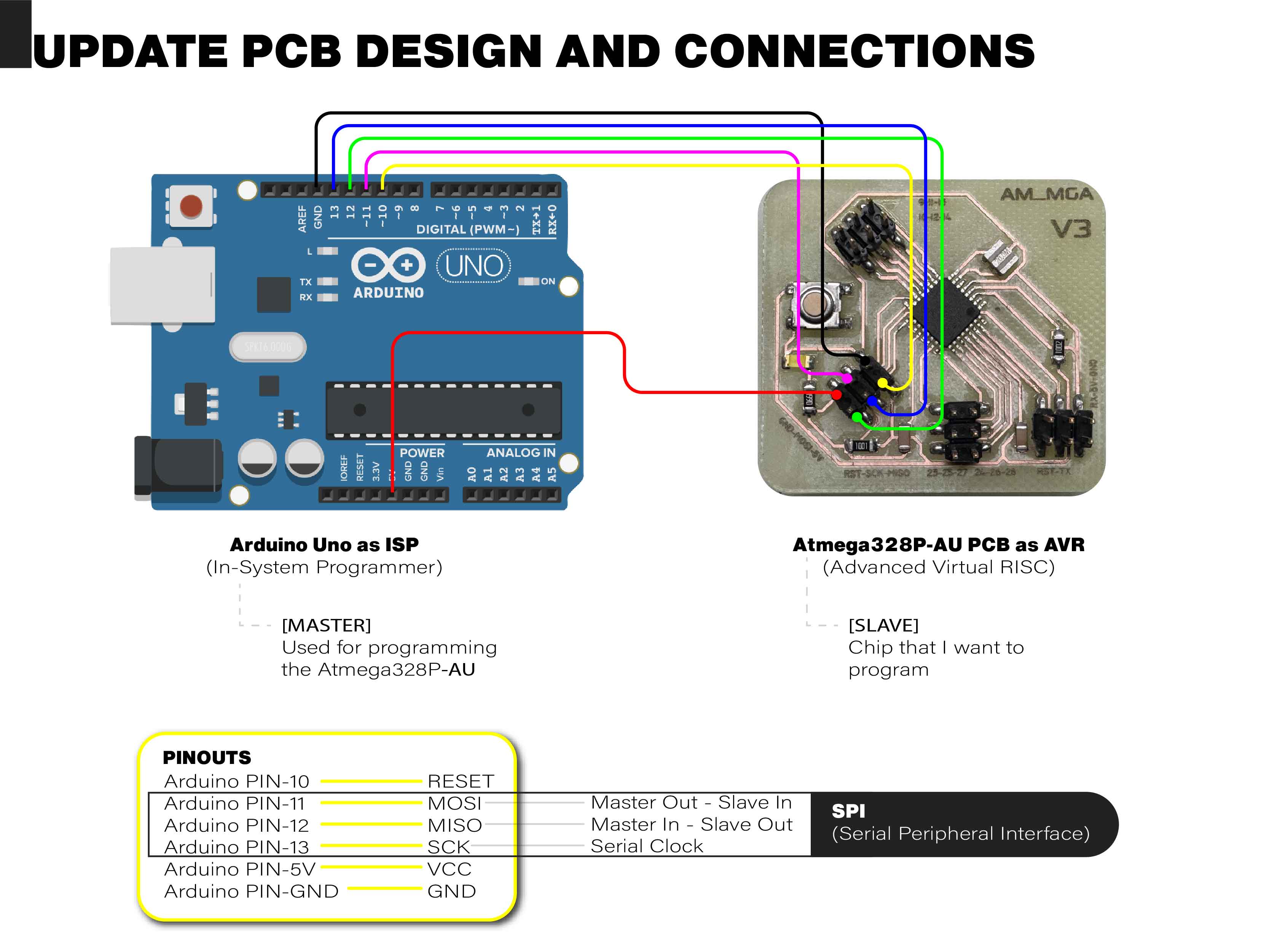
For this, I used an Arduino Uno as an In-System Programmer (ISP).
An ISP allows me to program AVR controllers without having to remove them from the PCB. For this, we need 6 ports.
Serial Peripheral Interface (SPI):
- Master In - Slave Out (MISO)
- Master Out - Slave In (MOSI)
- Serial Clock (SCK)
The Master is the ISP (Arduino Uno) that I use to program the ATmega.
The Slave is the AVR chip (ATmega328P-AU) that I want to program.
The other pins are for the 5V and GND power supply and the Reset.
I updated the board design because the previous one had some issues with interference between certain traces, and after that, I repeated the bootloader burning process.
Engraving PCB tags - Make things easier for yourself
A helpful tip to simplify and speed up the connection process is to engrave the board's pins using a laser cutter. In the Epilog machine, I utilized a power setting of 100 and a speed of 30.
Programming process

Uploading sketchs
To upload the sketch to the board, you must verify the pin connections as in the previous step and then upload using the "Upload Using Programmer" option.

Color Sensor (CS)
Design concept
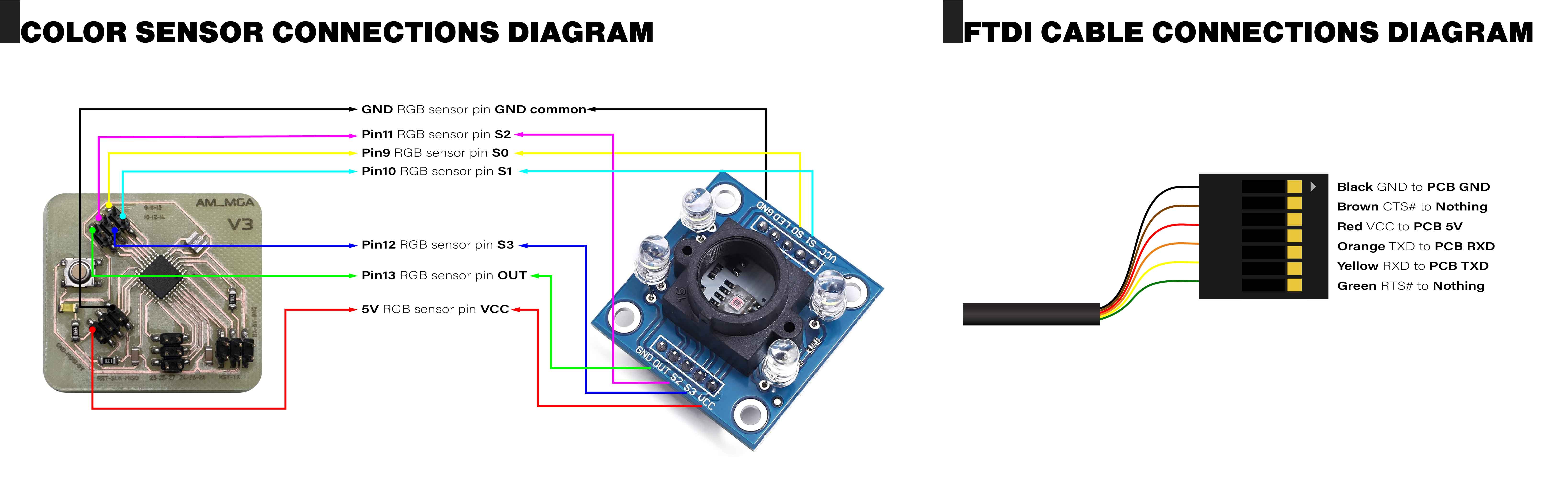
The concept is to utilize an RGB sensor to distinguish colors.
(CS) Connections diagram
Atmega Pinout
To program the code on the ATmega328P using Arduino IDE, I have to use the controller's pinout to assign the corresponding pins from Arduino. For this, I refer to the datasheet of the ATmega328P pinout.

Color sensor connection
Mistakes and Learnings

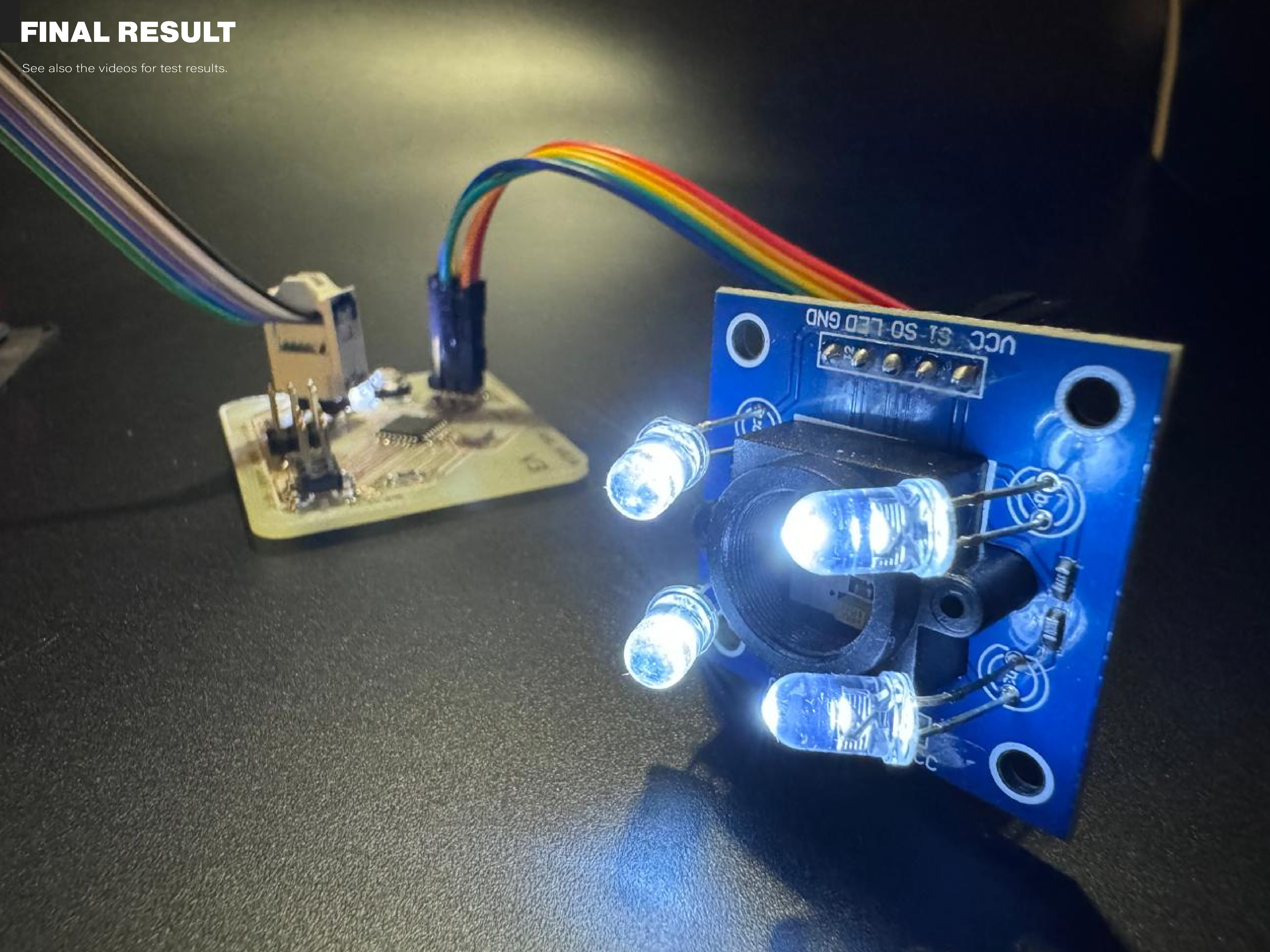
Result
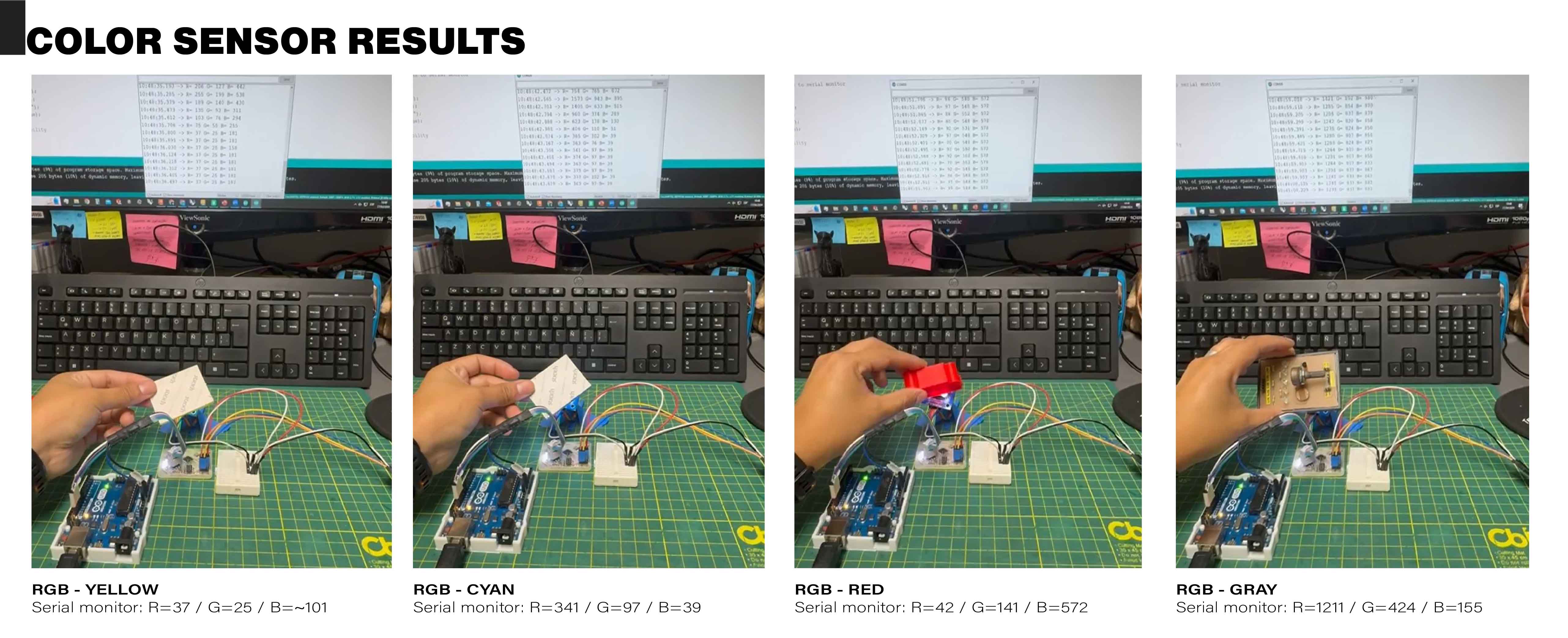
(CS) Color Sensor first tests
It is important to note that the RGB sensor was not properly calibrated, and the ambient lighting conditions were not conducive to accurate readings.