WEEK 9 - Output Devices
Checklist:
- Add an output device to a microcontroller board you've designed and program it to do something.
Learnings from the group assignment
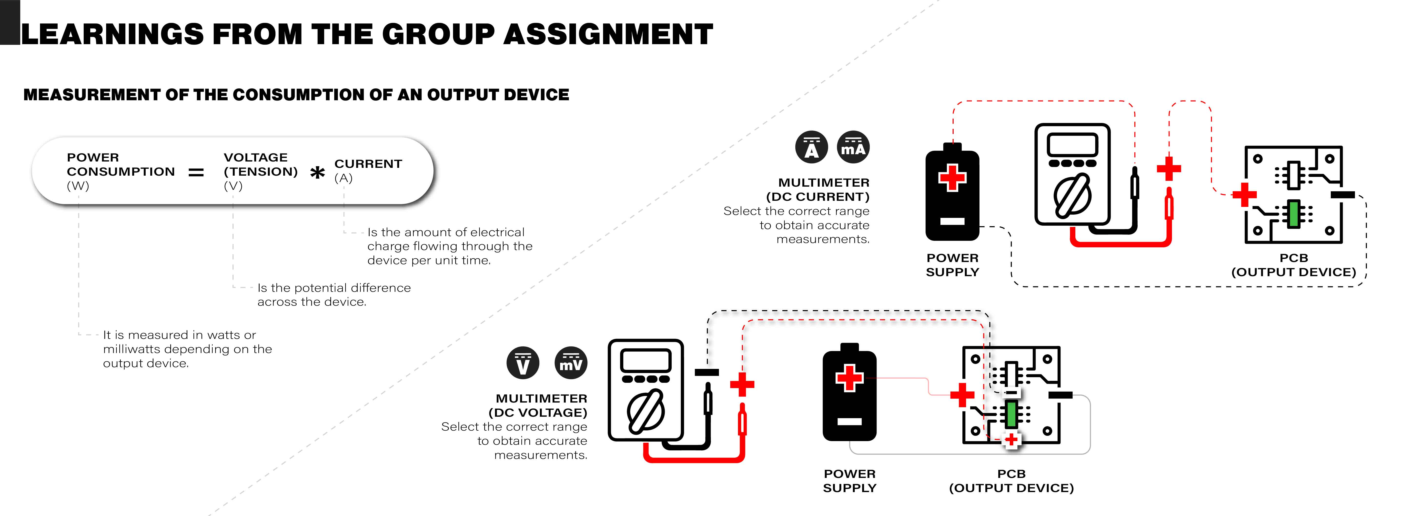
The group work involved using a multimeter to measure the power consumption of an output device. Below is a summary of the formula used to find the power consumption of a board or device and the connections to be made.
To measure the voltage of an output device on a PCB, connect the multimeter in parallel with the device, set it to DC voltage mode, select the appropriate range, and observe the reading to determine the potential difference across the device. You can measure the entire PCB as well as specific components. If the value displayed on the multimeter is negative, it indicates that the probes are connected in reverse.
Programming and design process and Results
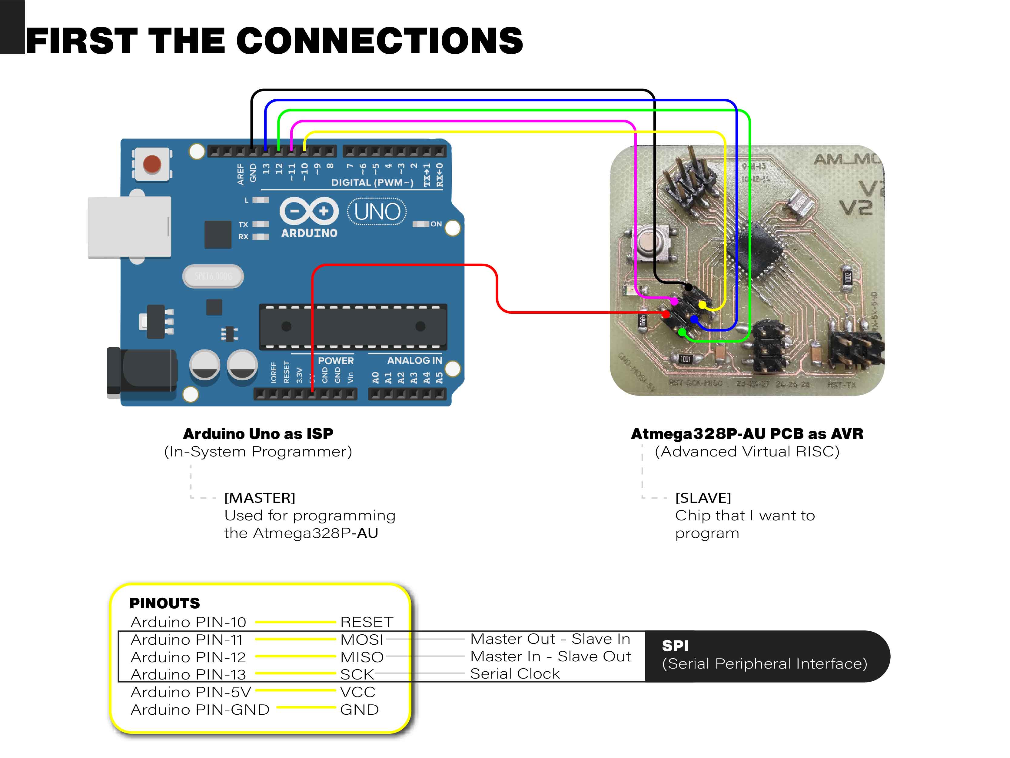
Connections before the programming
For this, I used an Arduino Uno as an In-System Programmer (ISP).
An ISP allows me to program AVR controllers without having to remove them from the PCB. For this, we need 6 ports.
Serial Peripheral Interface (SPI):
- Master In - Slave Out (MISO)
- Master Out - Slave In (MOSI)
- Serial Clock (SCK)
The Master is the ISP (Arduino Uno) that I use to program the ATmega.
The Slave is the AVR chip (ATmega328P-AU) that I want to program.
The other pins are for the 5V and GND power supply and the Reset.
I used this link as reference for starting the whole process.
Engraving PCB tags - Make things easier for yourself
A helpful tip to simplify and speed up the connection process is to engrave the board's pins using a laser cutter. In the Epilog machine, I utilized a power setting of 100 and a speed of 30.
Programming process

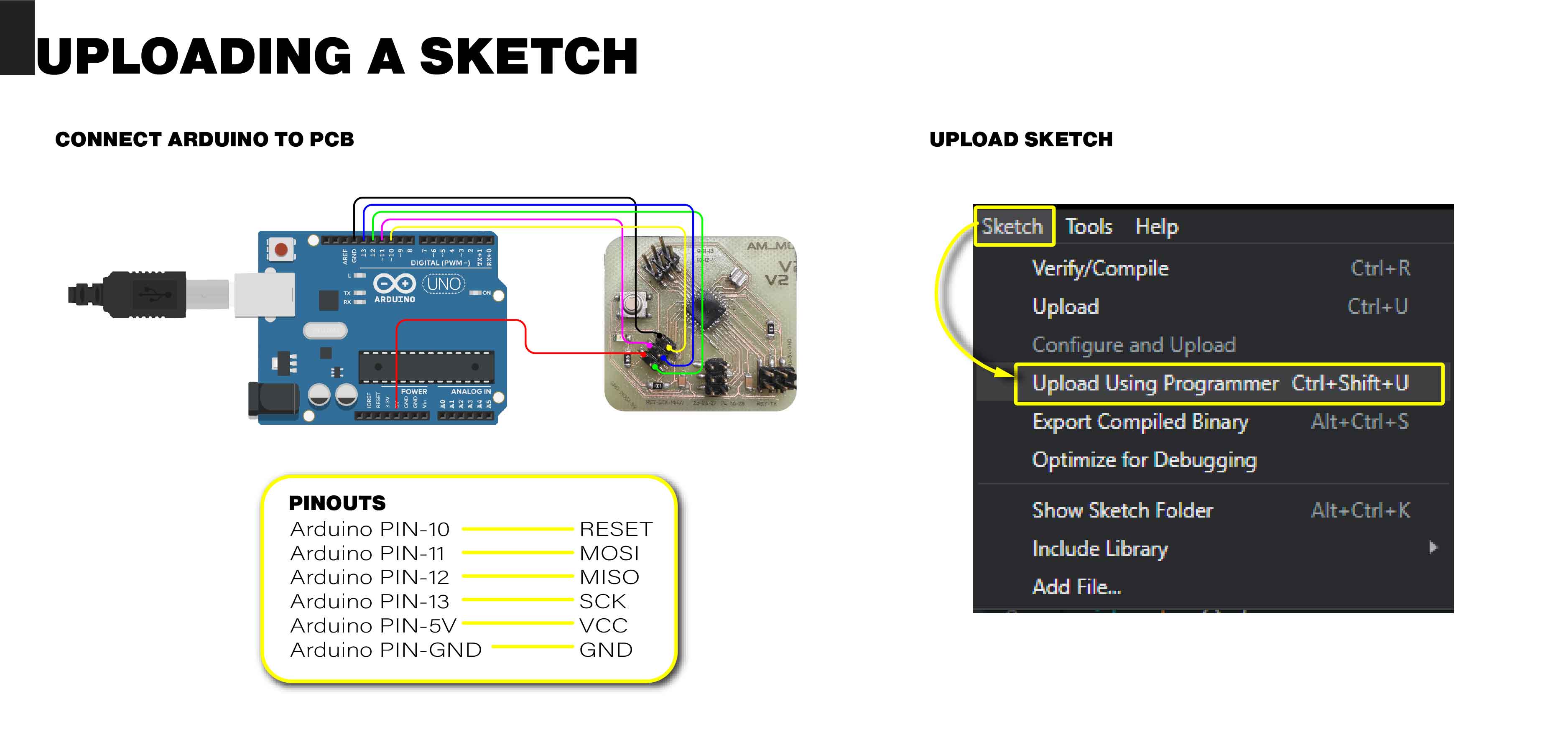
Uploading sketchs
To upload the sketch to the board, you must verify the pin connections as in the previous step and then upload using the "Upload Using Programmer" option.
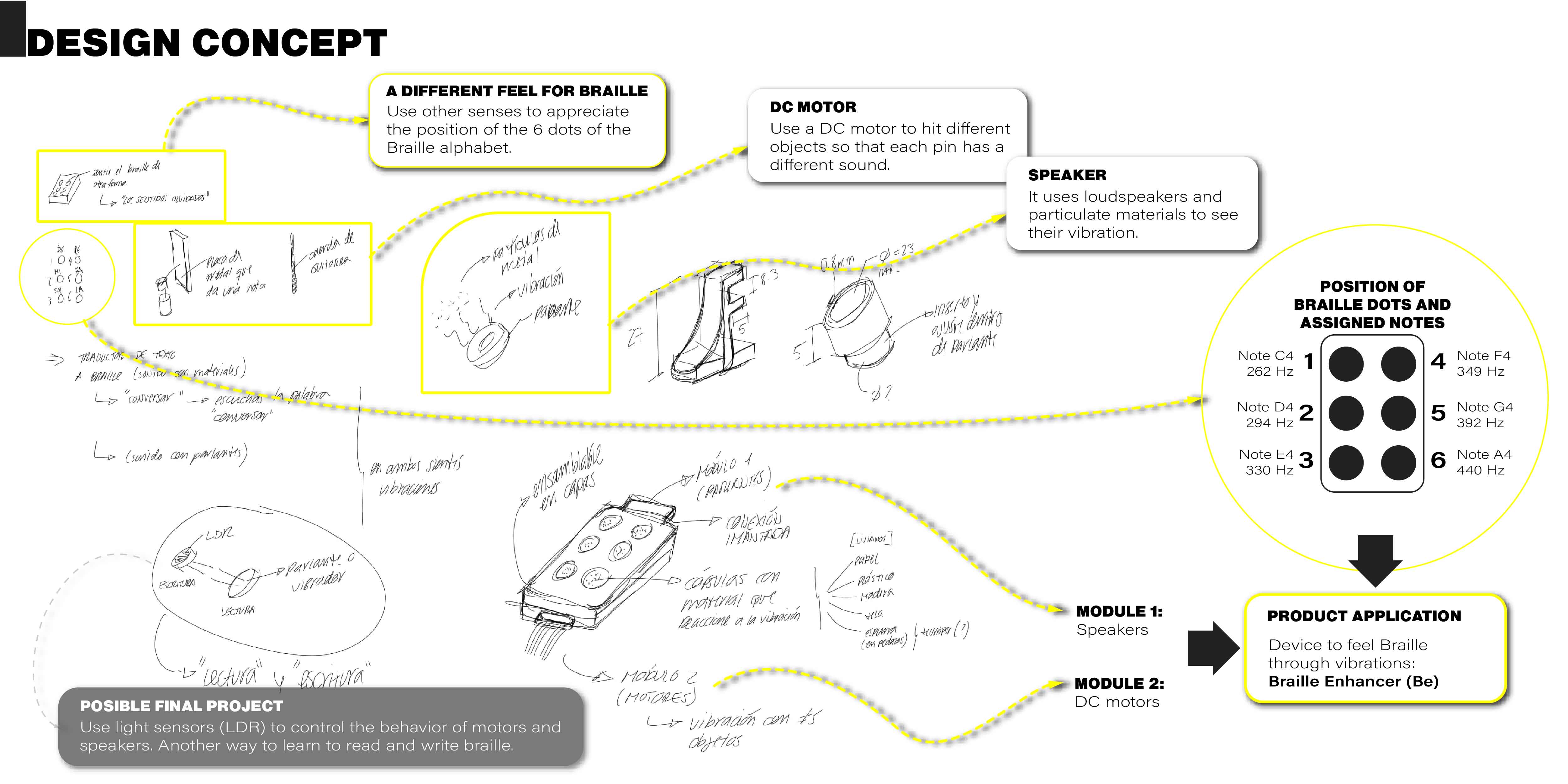
Braille Enhancer (Be)
Design concept
The idea is to interact with the Braille system using senses other than touch, in this case, using hearing and sight.
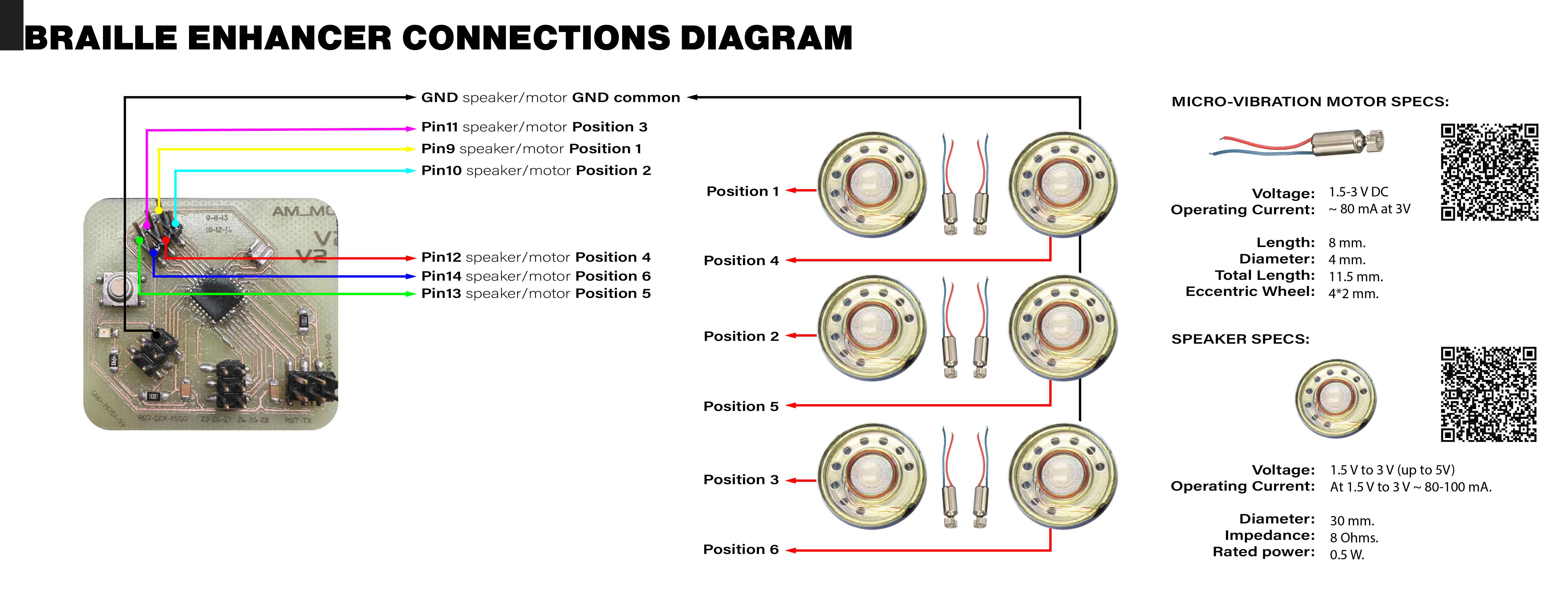
(Be) Connections diagram
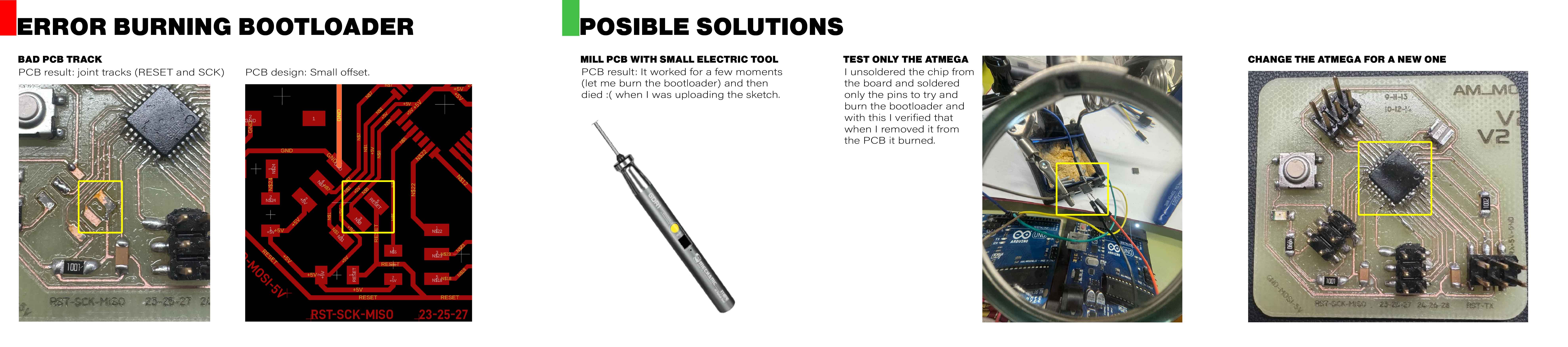
Mistakes and Learnings
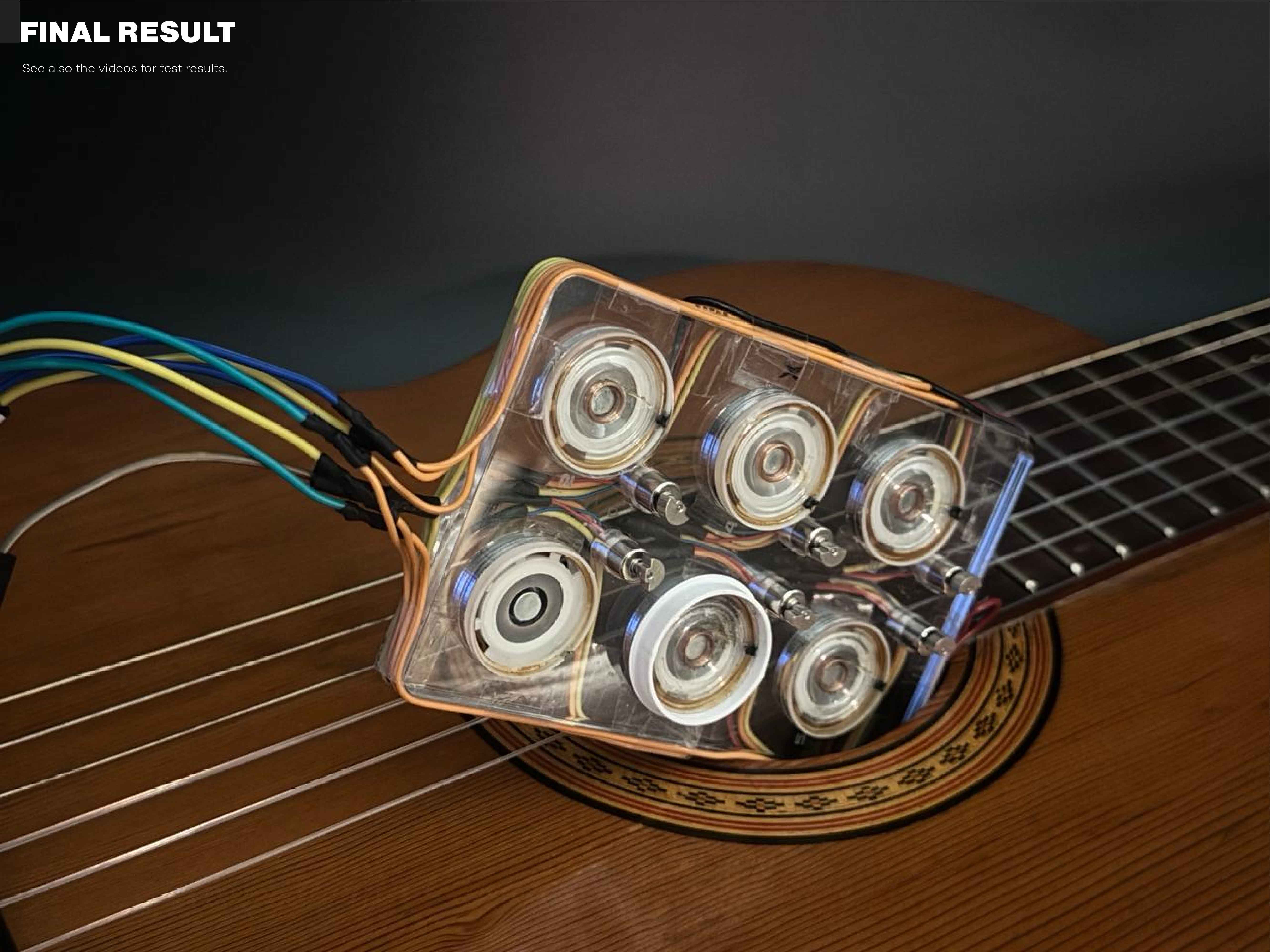
Result
(Be) Braille Enhancer first tests