Week 5: 3D Scanning and Printing
This week, I learned how to utilize a 3D scanner for scanning medium and small parts. Separately, I used 3D printing technologies to design an object that could not be easily fabricated using traditional manufacturing methods. For this assignment, I decided to print a Fab Academy fidget spinner with an integrated print-in-place bearing design.
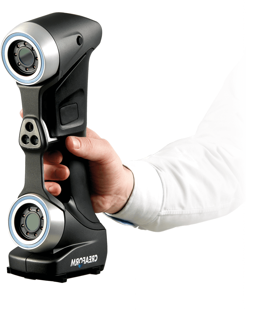
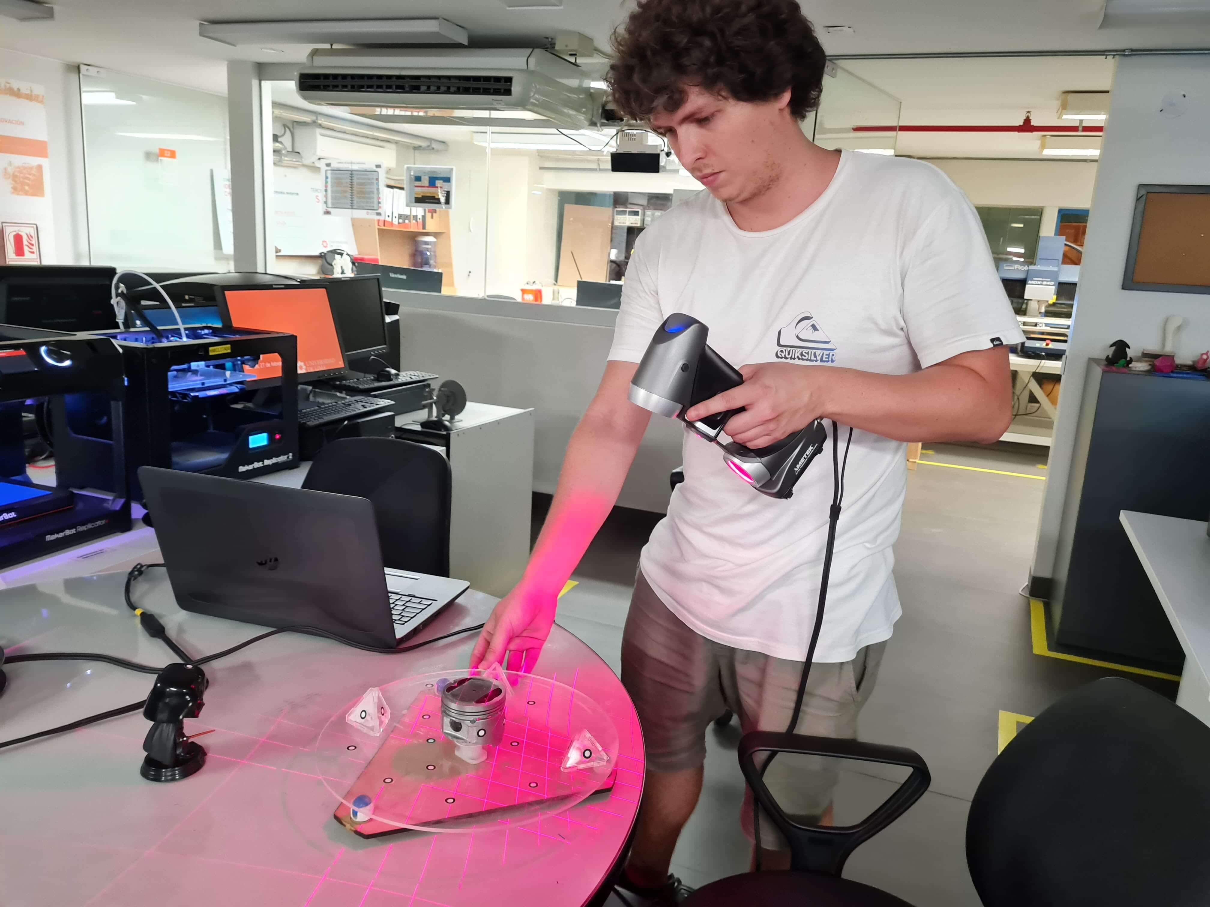
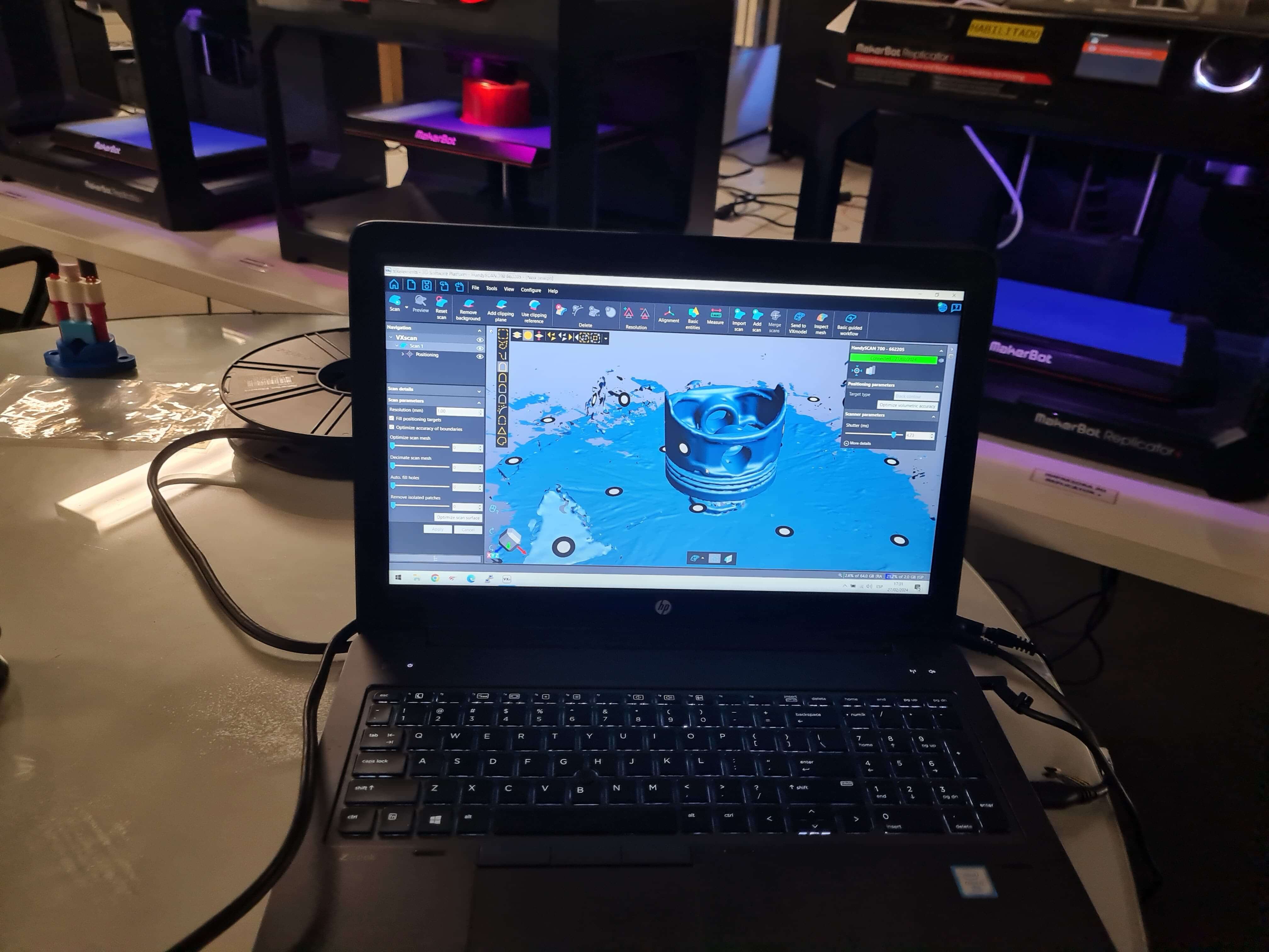
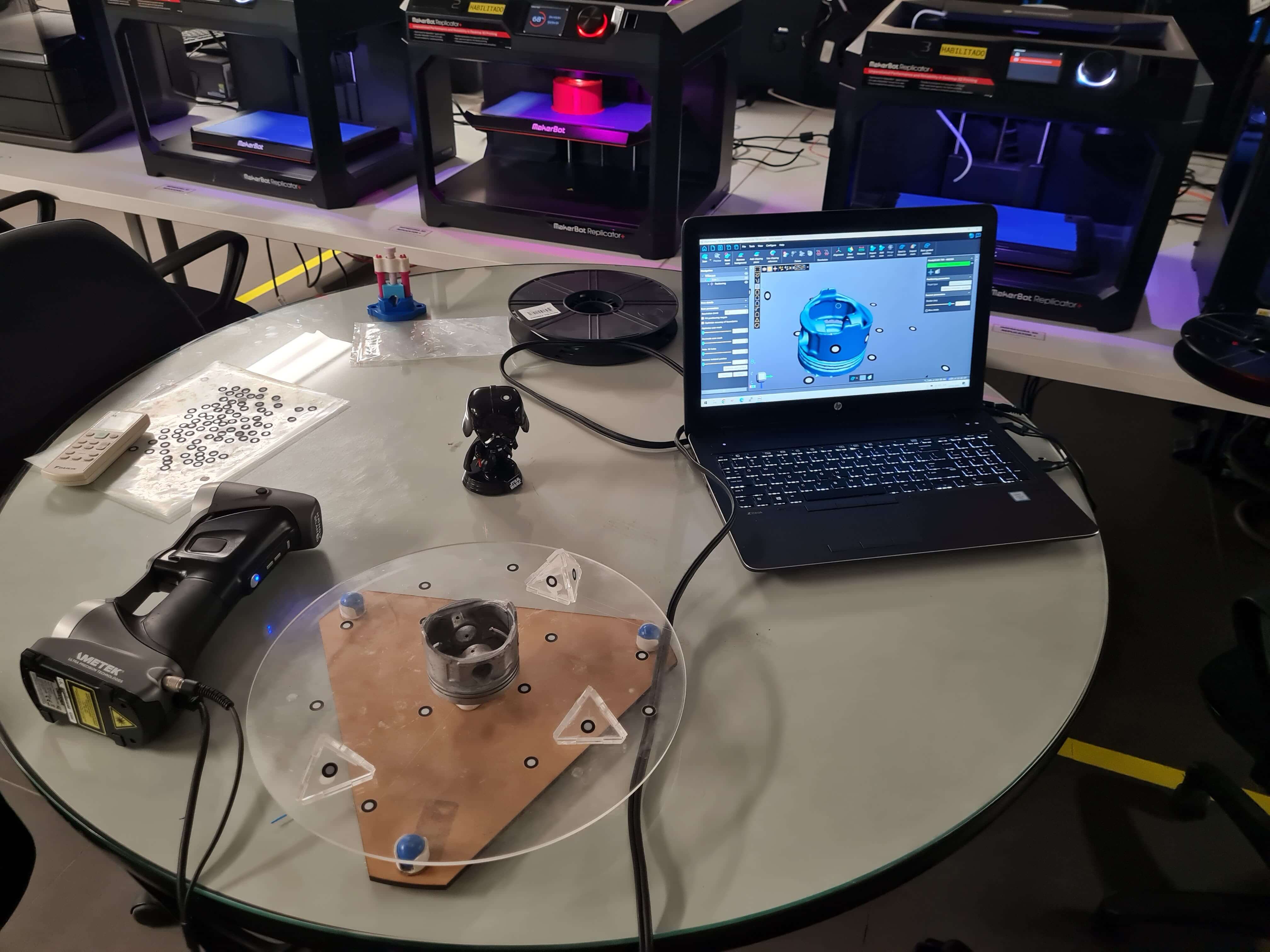
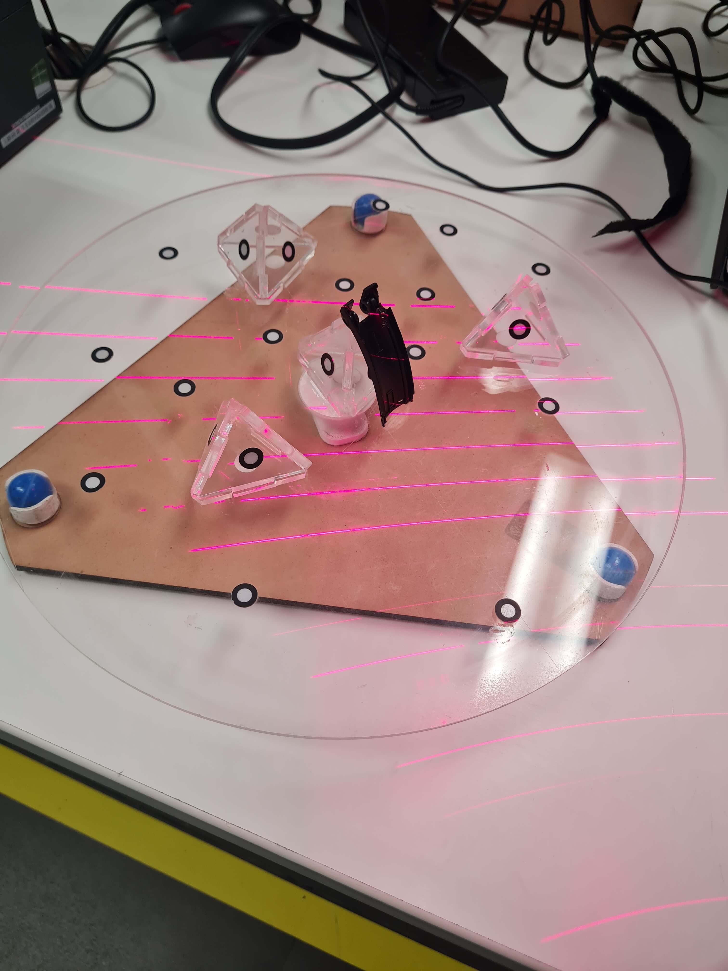
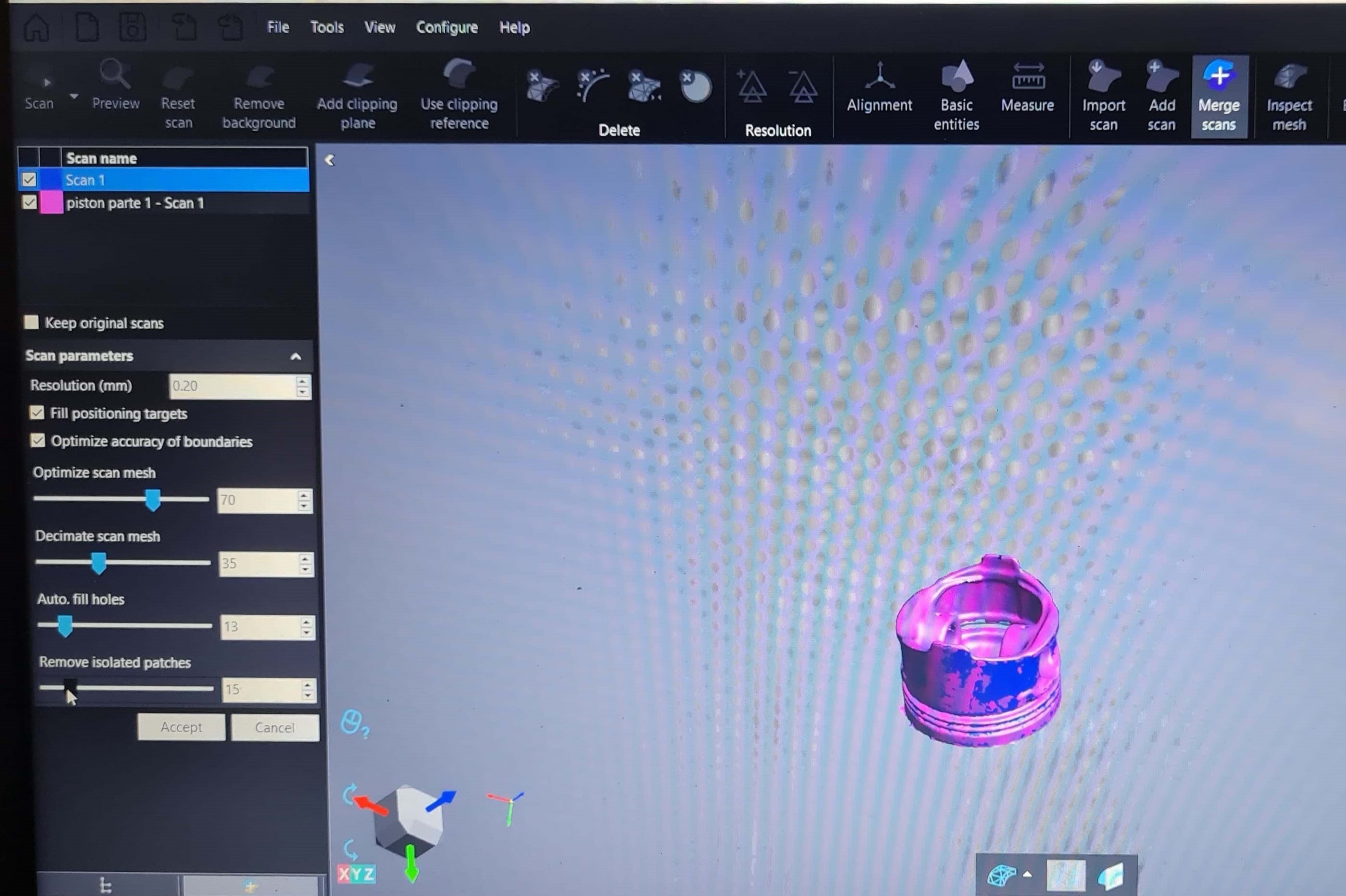
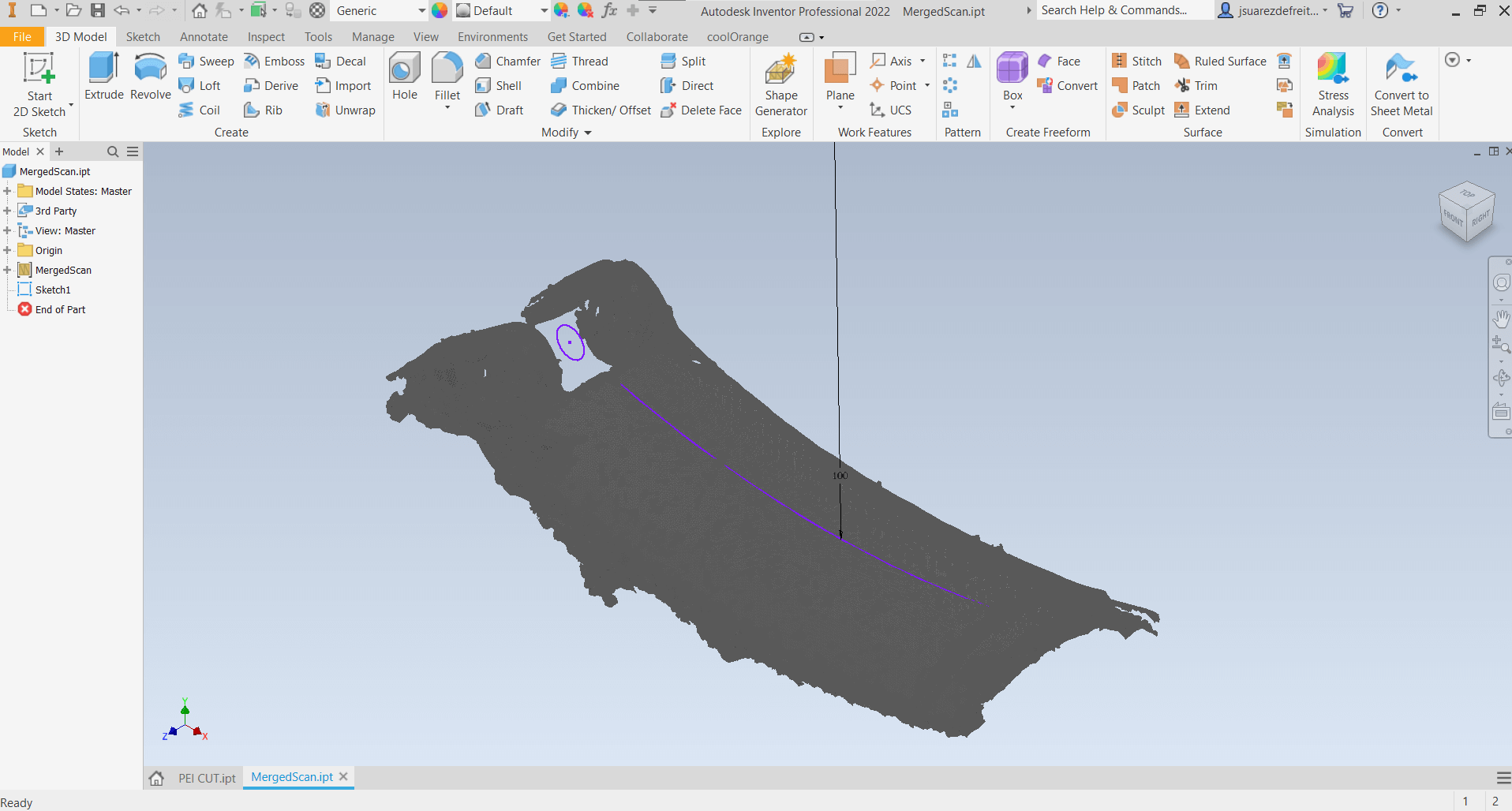
With this challenge, I experimented with various positions to scan as much surface area as possible from each point. The best position I found was to lay down the part on each side. However, due to limitations in resolution, the scan couldn't capture small details, such as some walls of the model being just 0.5mm thick. Despite this, the scanned mesh will serve as a useful reference in Inventor, providing a clearer picture of the part that needs to be replicated.
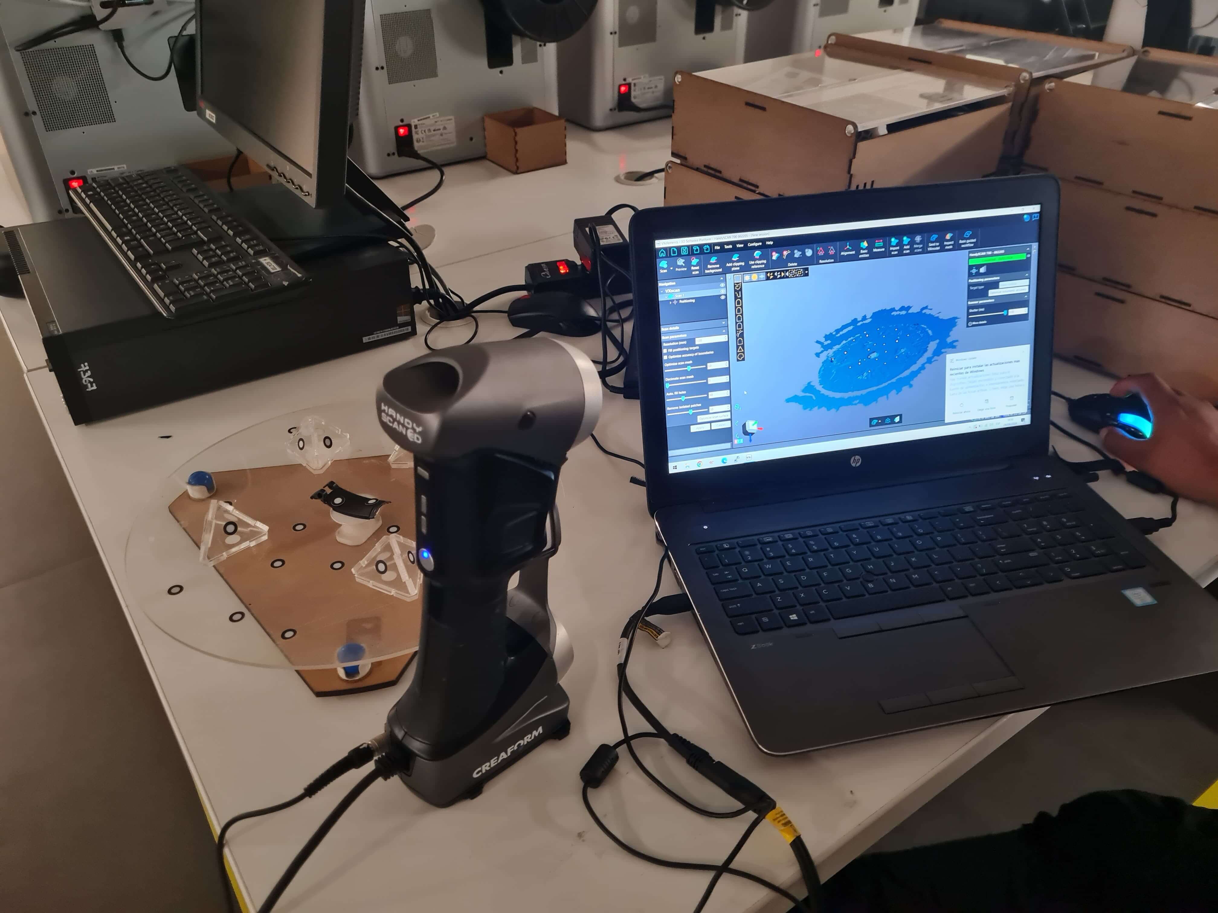
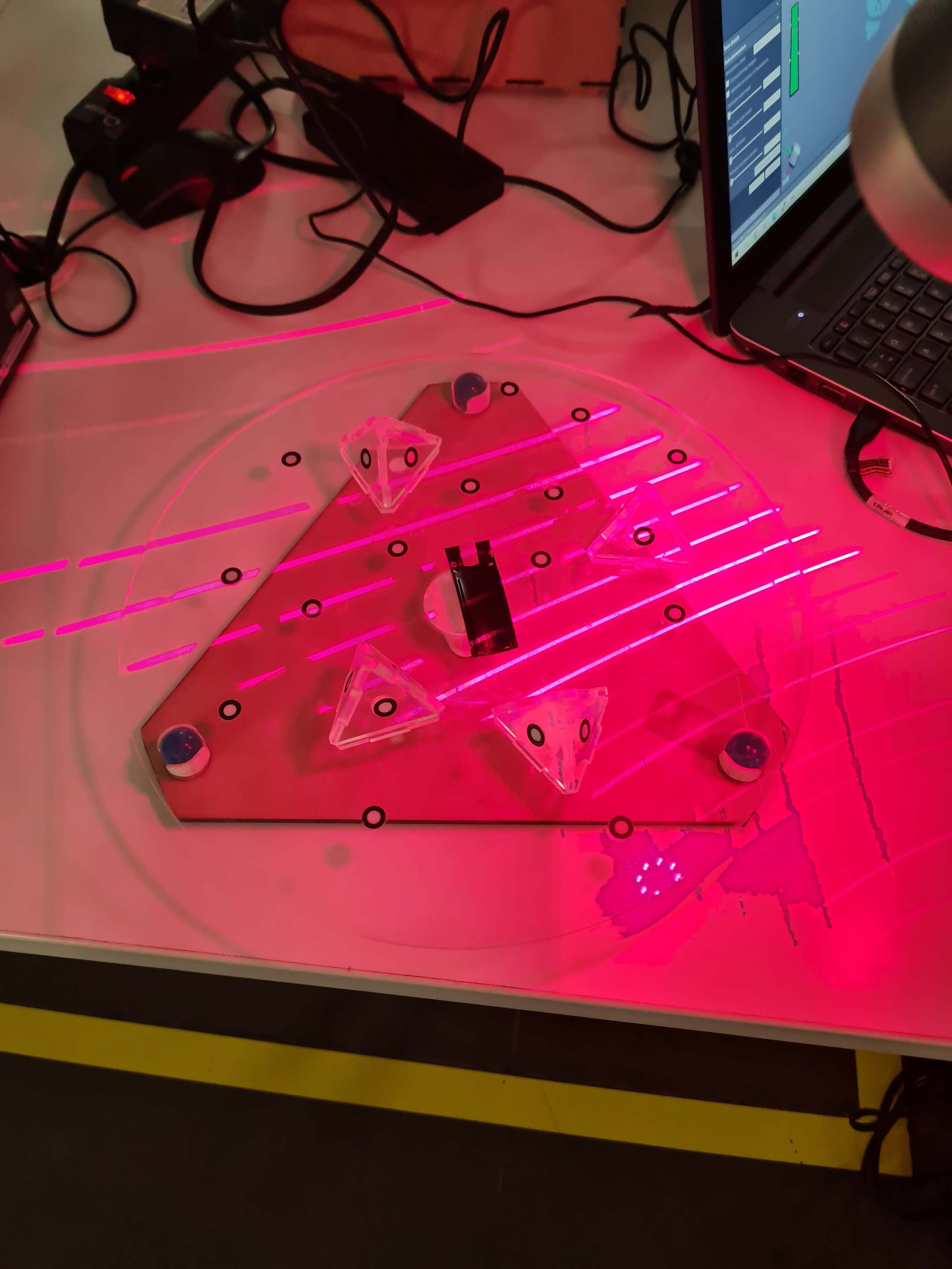
This is the final result of the scanning. Unfortunately, I was unable to close the mesh to create a solid model, as the scanning process was inconsistent. While I'm not entirely satisfied with the result, it still serves as a useful reference for future work.
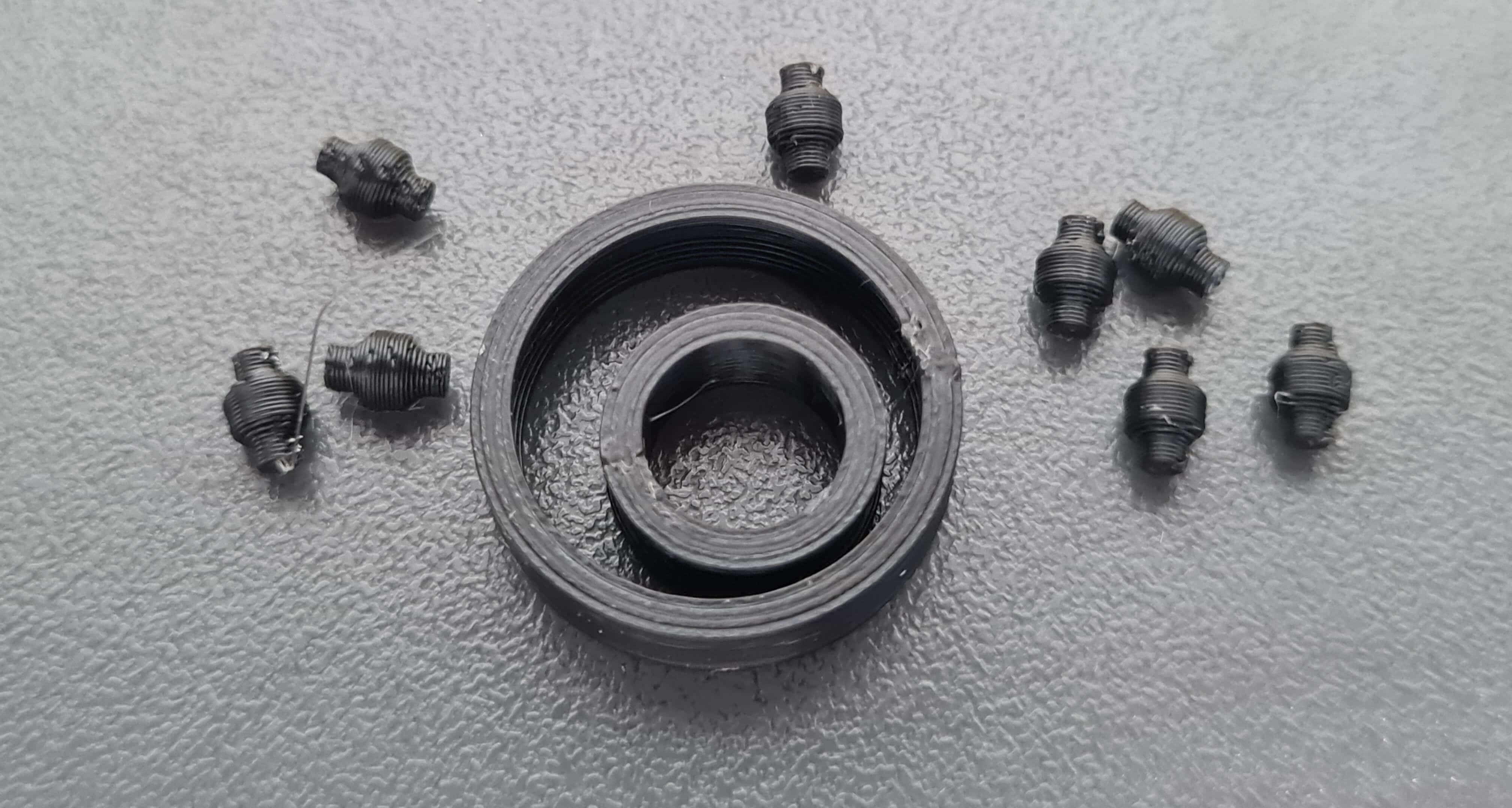
For the 3D design stage, I tested three main ideas. The first was spherical bearings with a flat spot at the bottom for better printability. However, FDM 3D printing struggles with printing complete spheres unless PVA dissolvable supports are used, which I didn't have. Therefore, the second and third ideas were more optimized for FDM printing without supports. The second idea was a cylindrical bearing with a chamfer. The third was an inverted design of the second idea. The problem with the second idea was that the bearings would rotate and disassemble when removed from the PEI sheet. By inverting the design, I achieved much better auto-alignment.
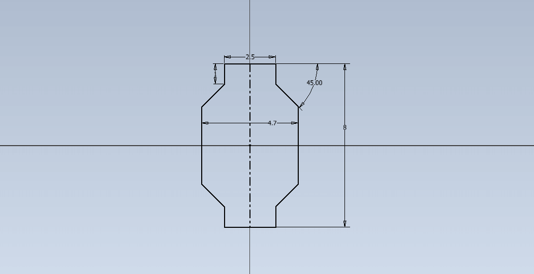
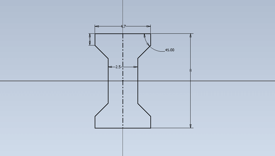
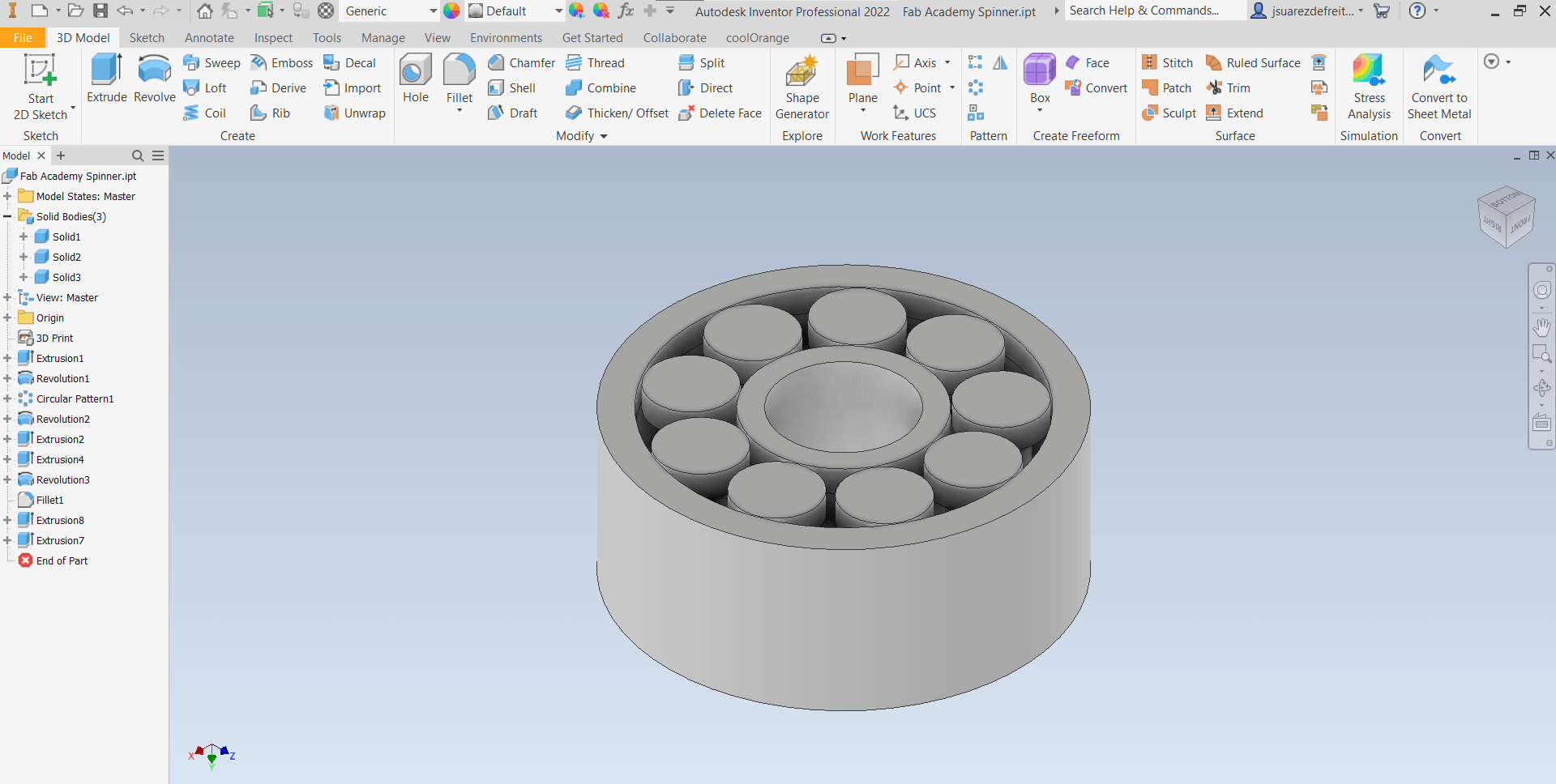
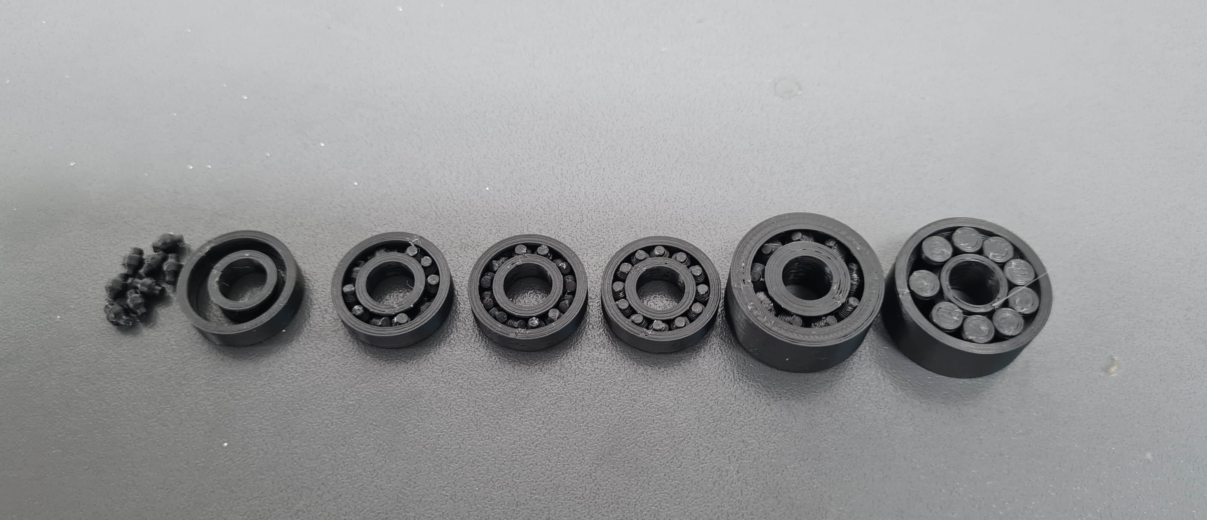
Due to a slicer issue, I needed to design the parts as separate solids and export them individually. However, these solids share a common origin, ensuring they align perfectly in the slicer. This approach was necessary because the slicer struggles to identify and segment parts with small tolerances, sometimes merging them, which is unacceptable.
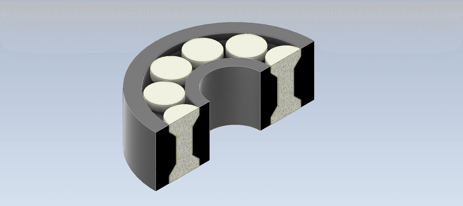
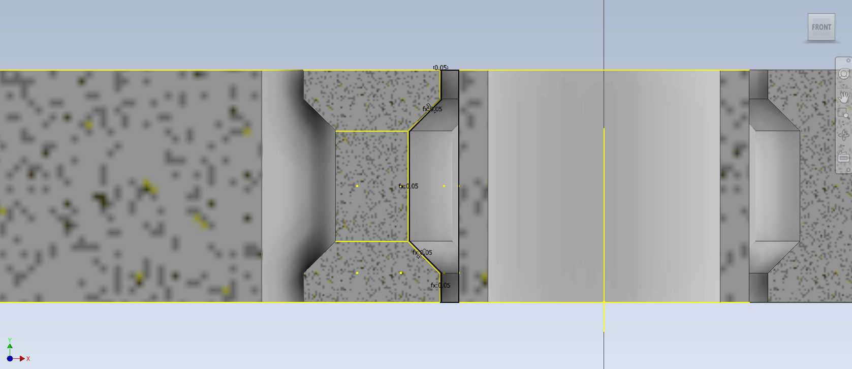
The main challenge of this 3D-printed design was managing the tolerances. I varied the tolerances from 0.1mm per side to 0.05mm per side, resulting in a total gap of 0.1mm. With this tolerance, I achieved a well-functioning print-in-place bearing. However, I needed to loosen each bearing due to minor stringing and the seams' bumps on the rolling elements inside the bearing. This problem was resolved by unsticking the rolling elements with a toothpick.
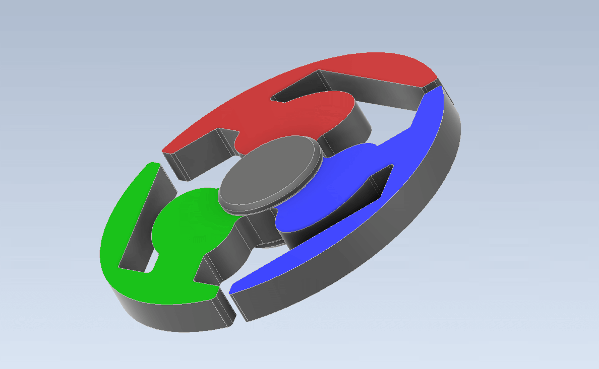
Once the bearing design functioned correctly and everything worked as planned, it was time to design the spinner itself! For this design, I imported an image of the Fab Academy logo into Inventor. I then proceeded to trace the design and extrude it, adapting it to create a suitable spinner.
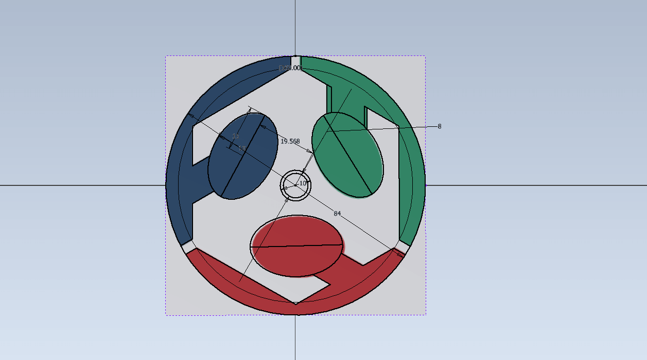
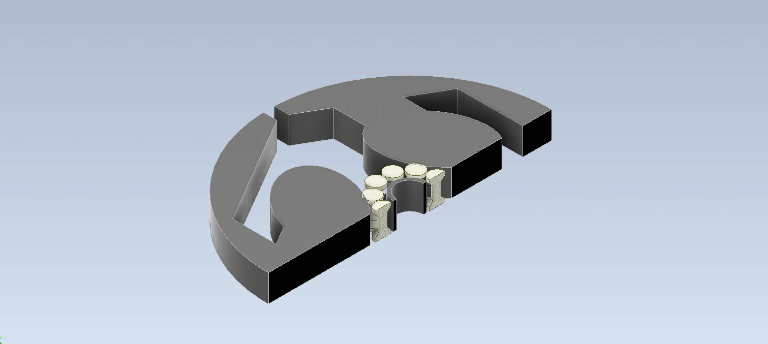
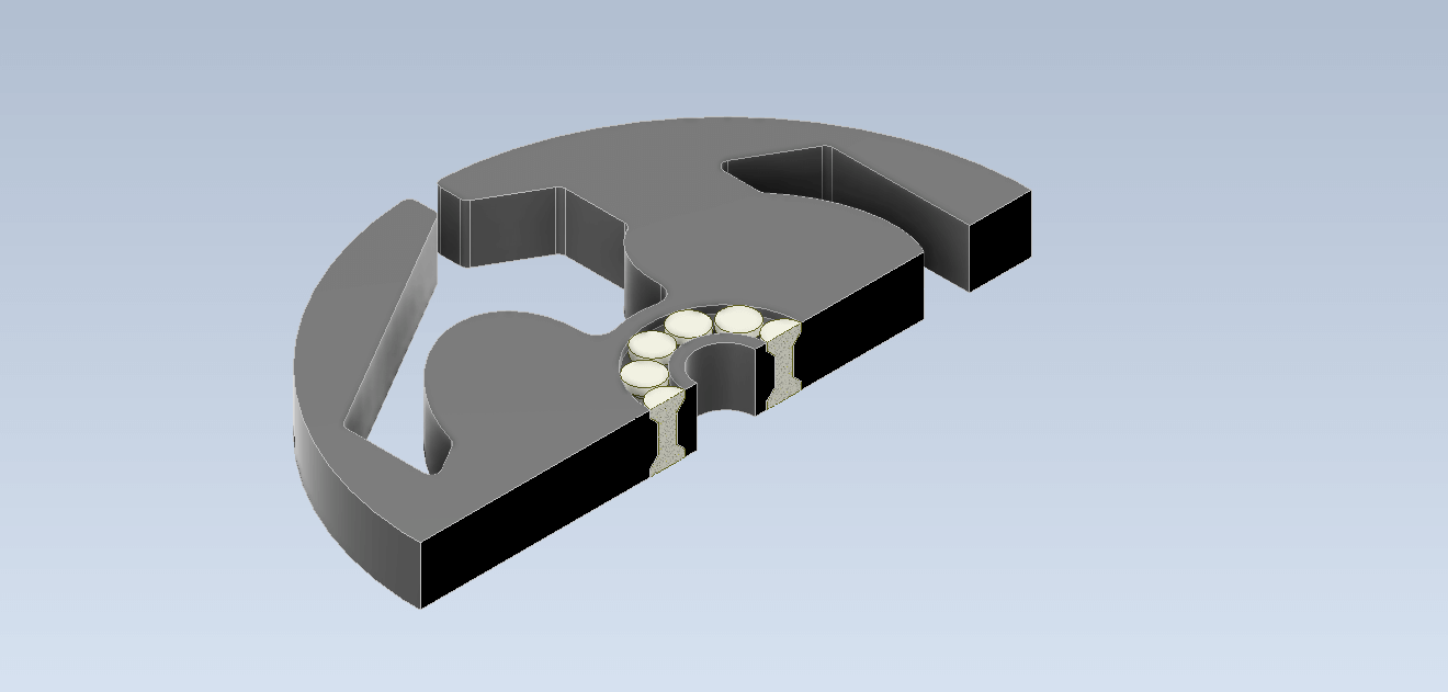
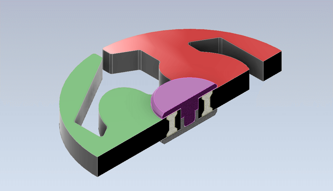
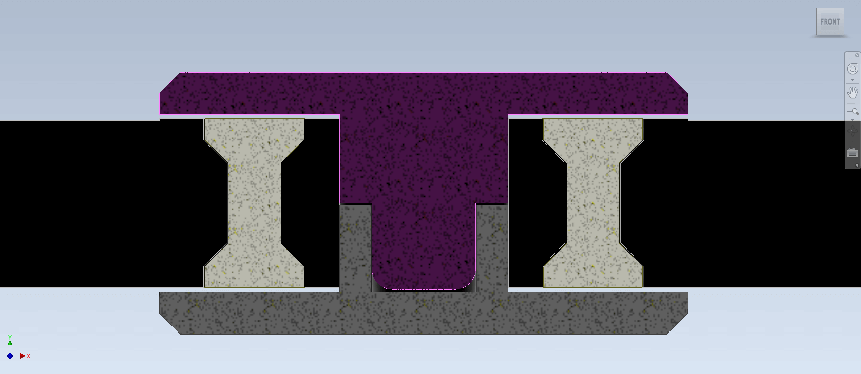
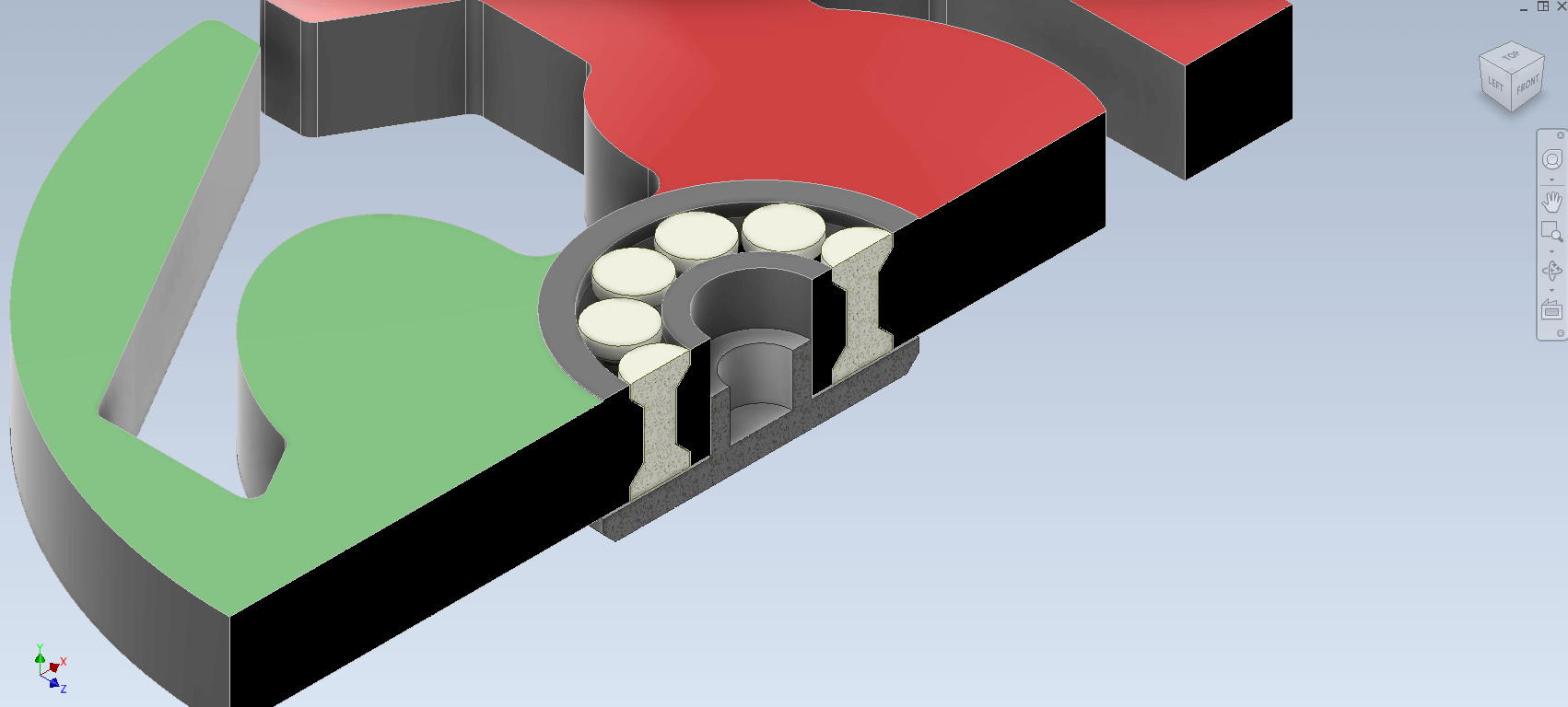
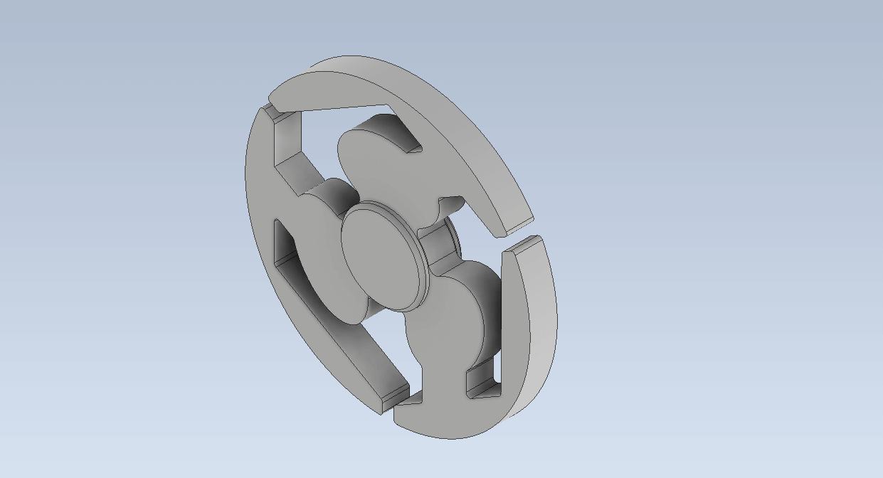
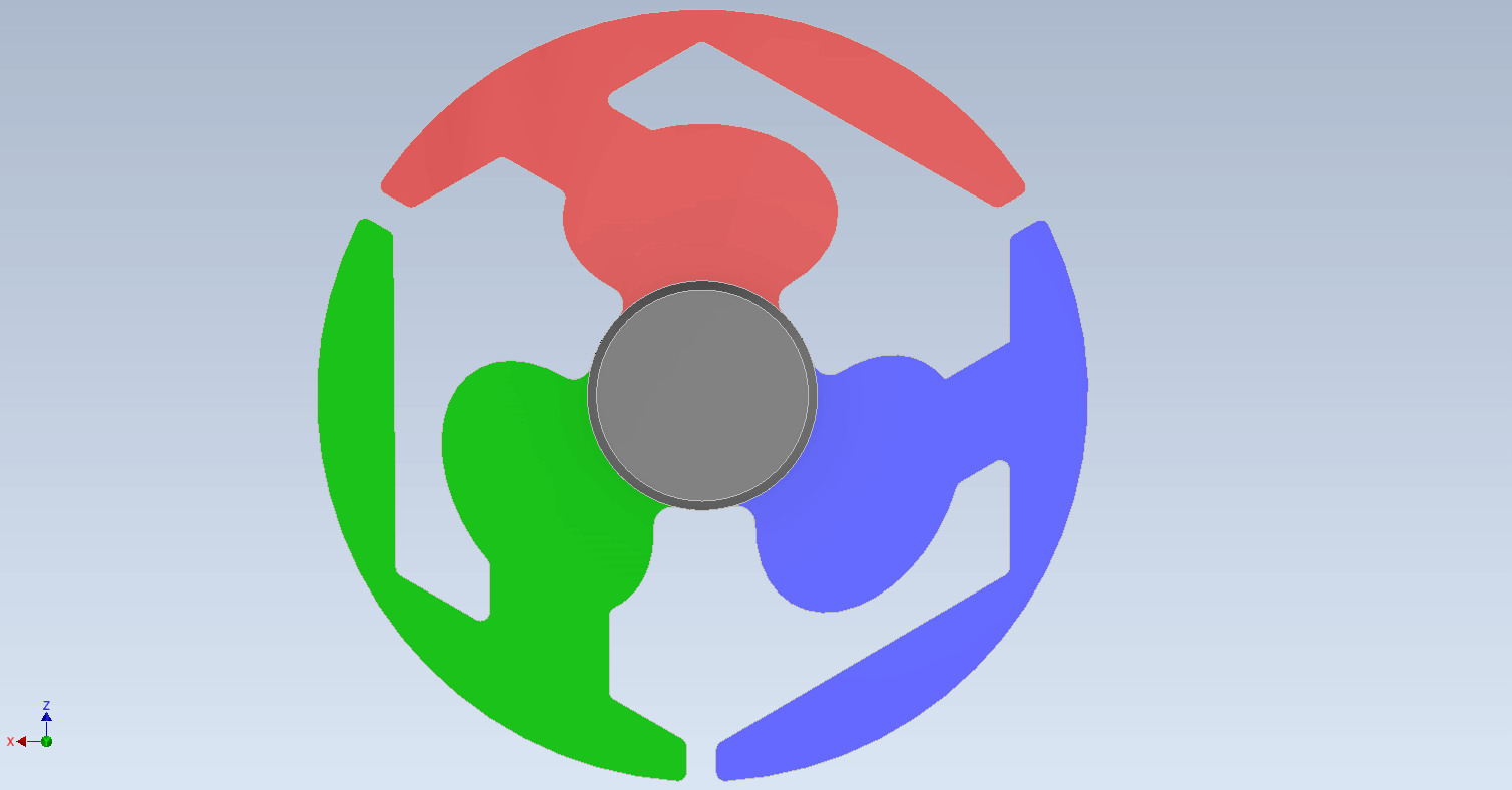
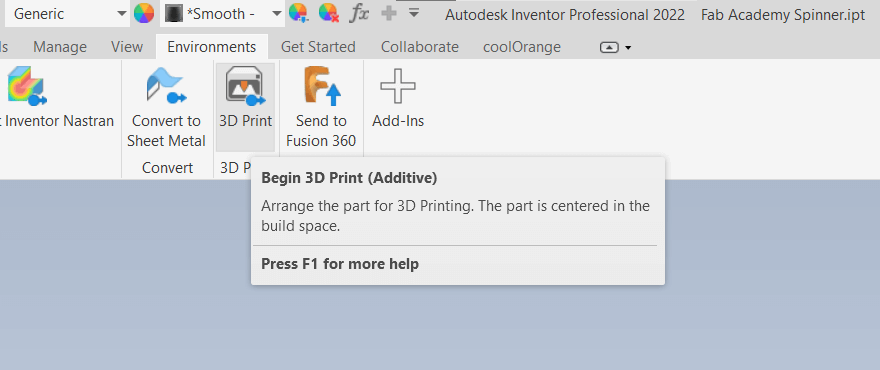
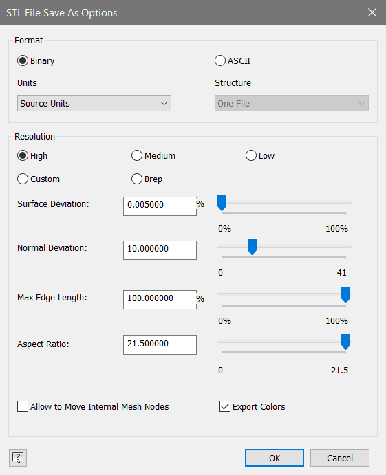
The next step is to export the STL files into the slicer for 3D printing. When exporting in Inventor Professional, it is recommended to use the 3D Printing environment, as it offers options for alignment and positioning before printing. Additionally, it's important to export using the highest quality STL possible to ensure the best print results.
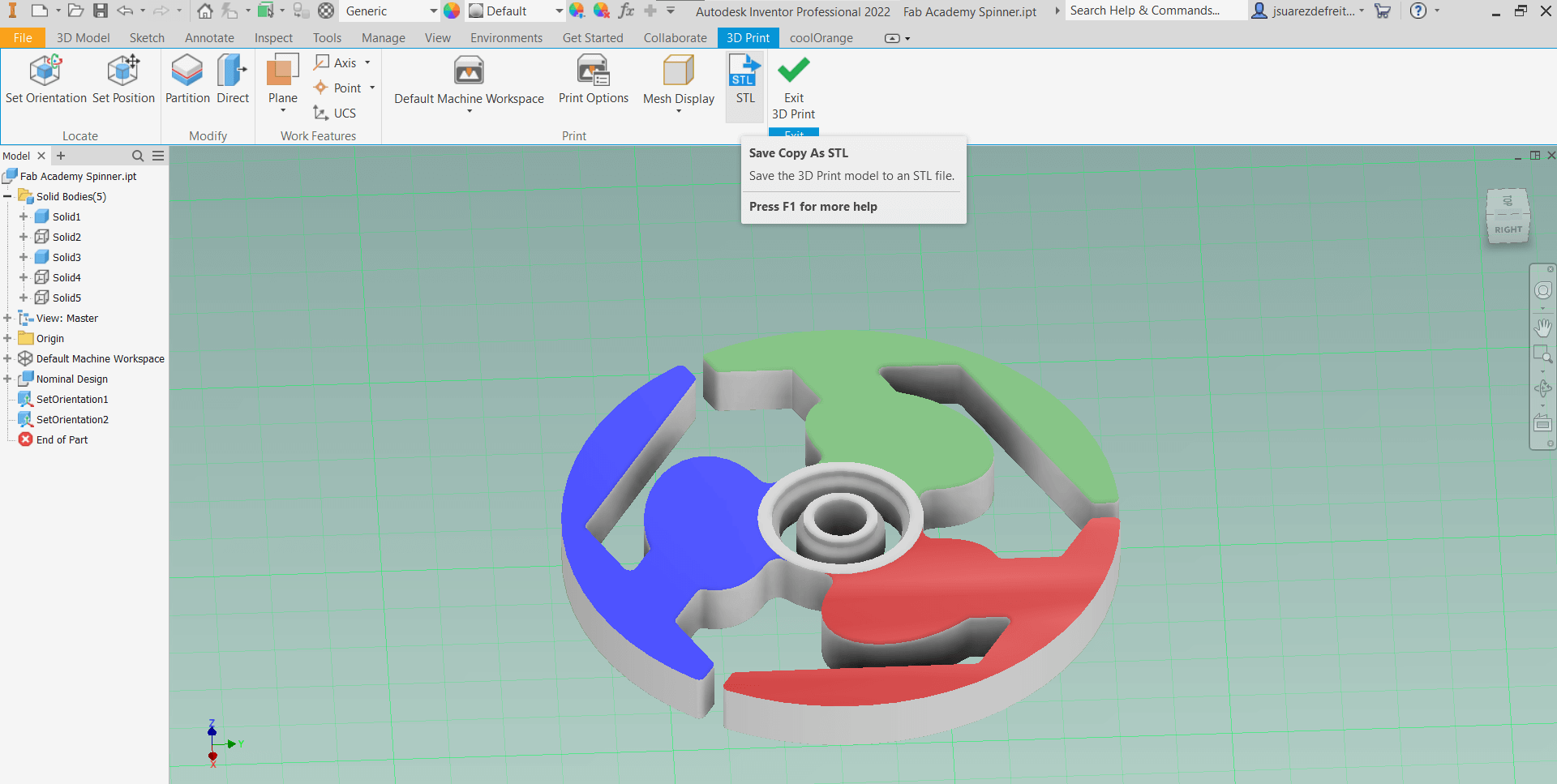
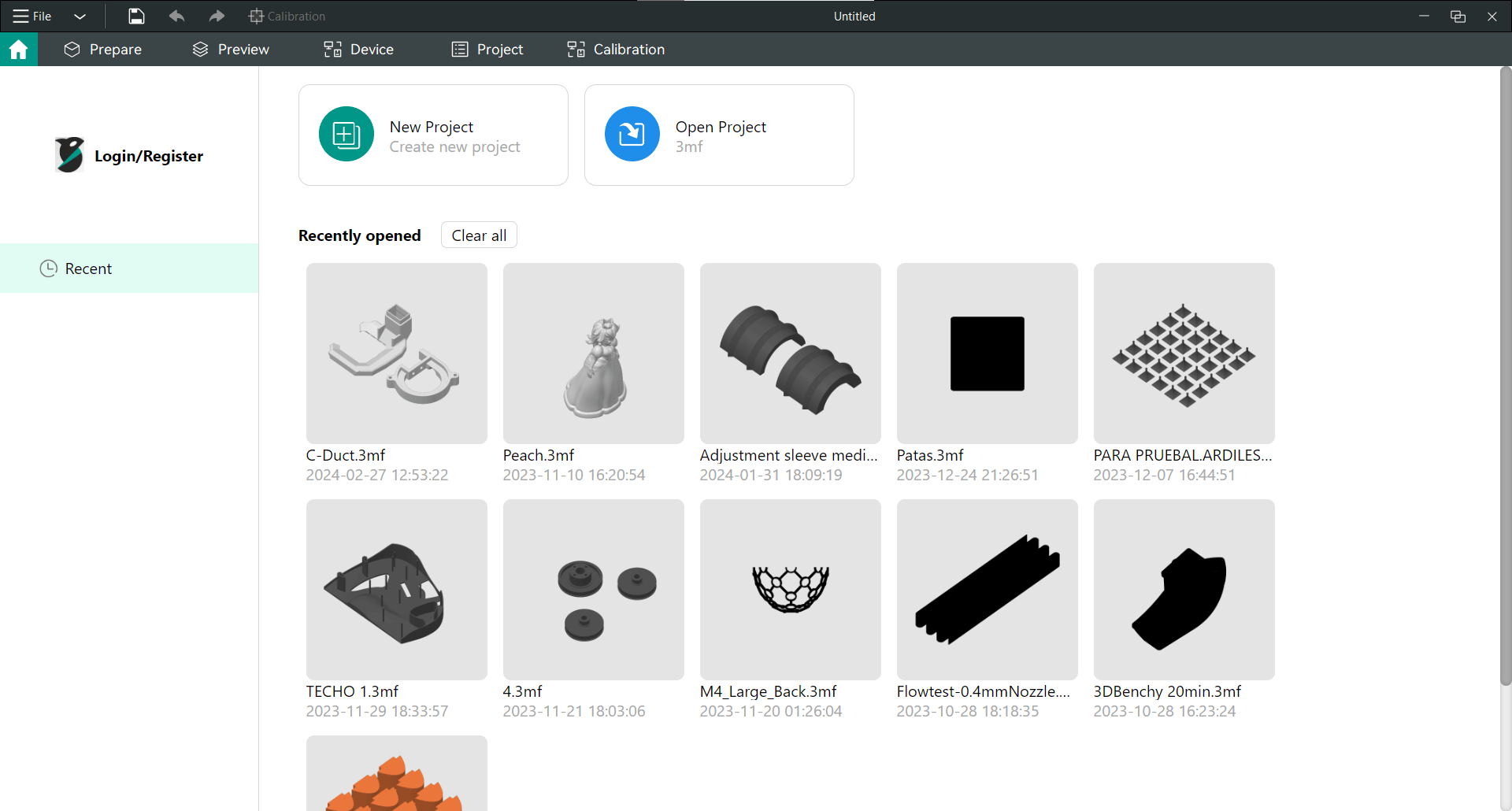
Drag your exported objects and drop them into the Orca Slicer platform to import them for slicing.
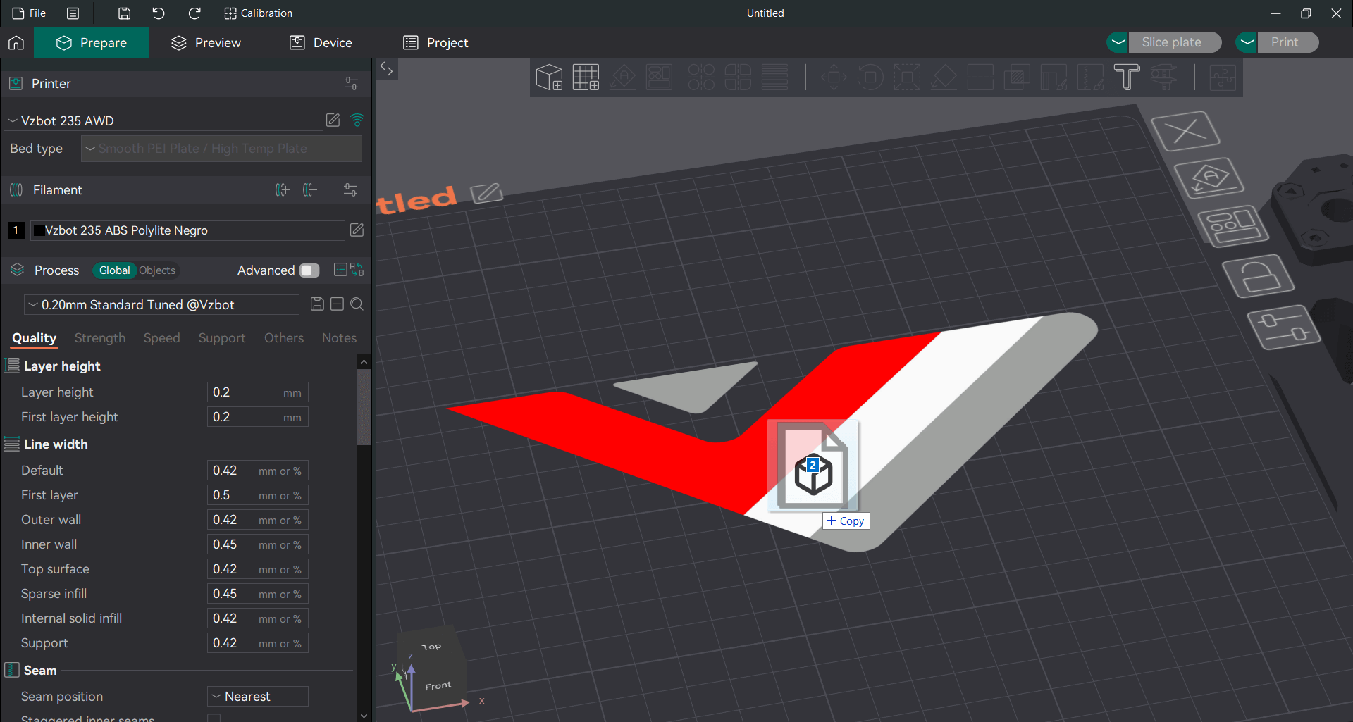
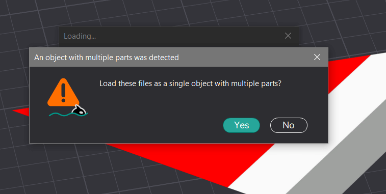
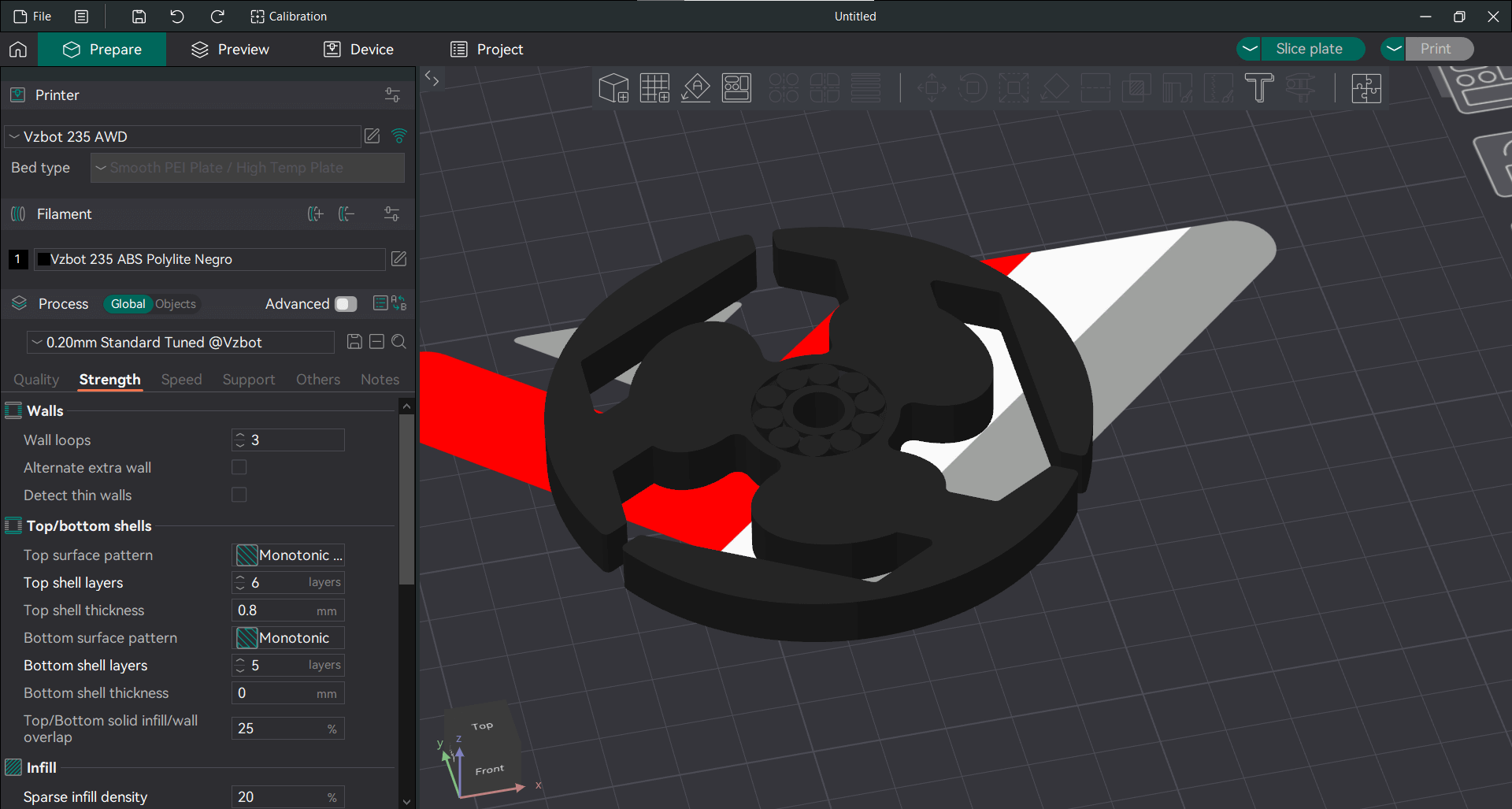
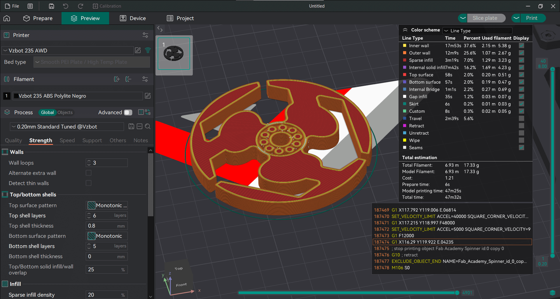
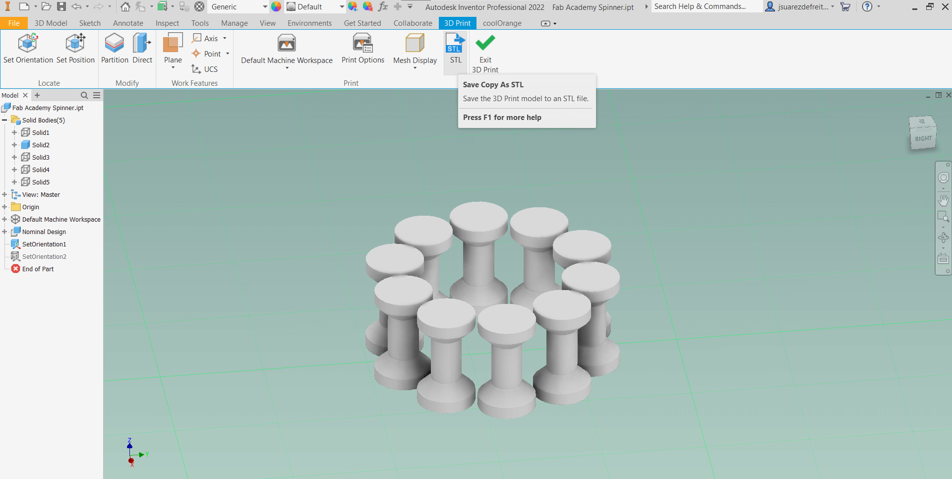
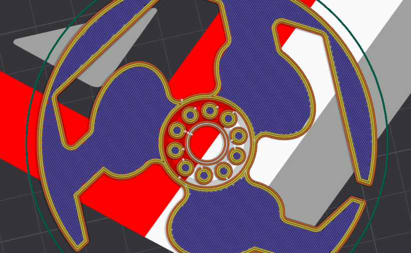
In this photo, you can see the slicing error that occurs when exporting as one solid with very small tolerances. The slicer merges them, making it impossible for the rolling mechanism to work. That's why I decided to export them as two separate solids to prevent the models from joining together.
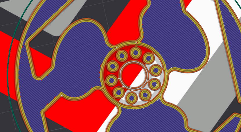
Here is a photo of the model when exported as two solids. As you can see, the parts are very close together but not merged.
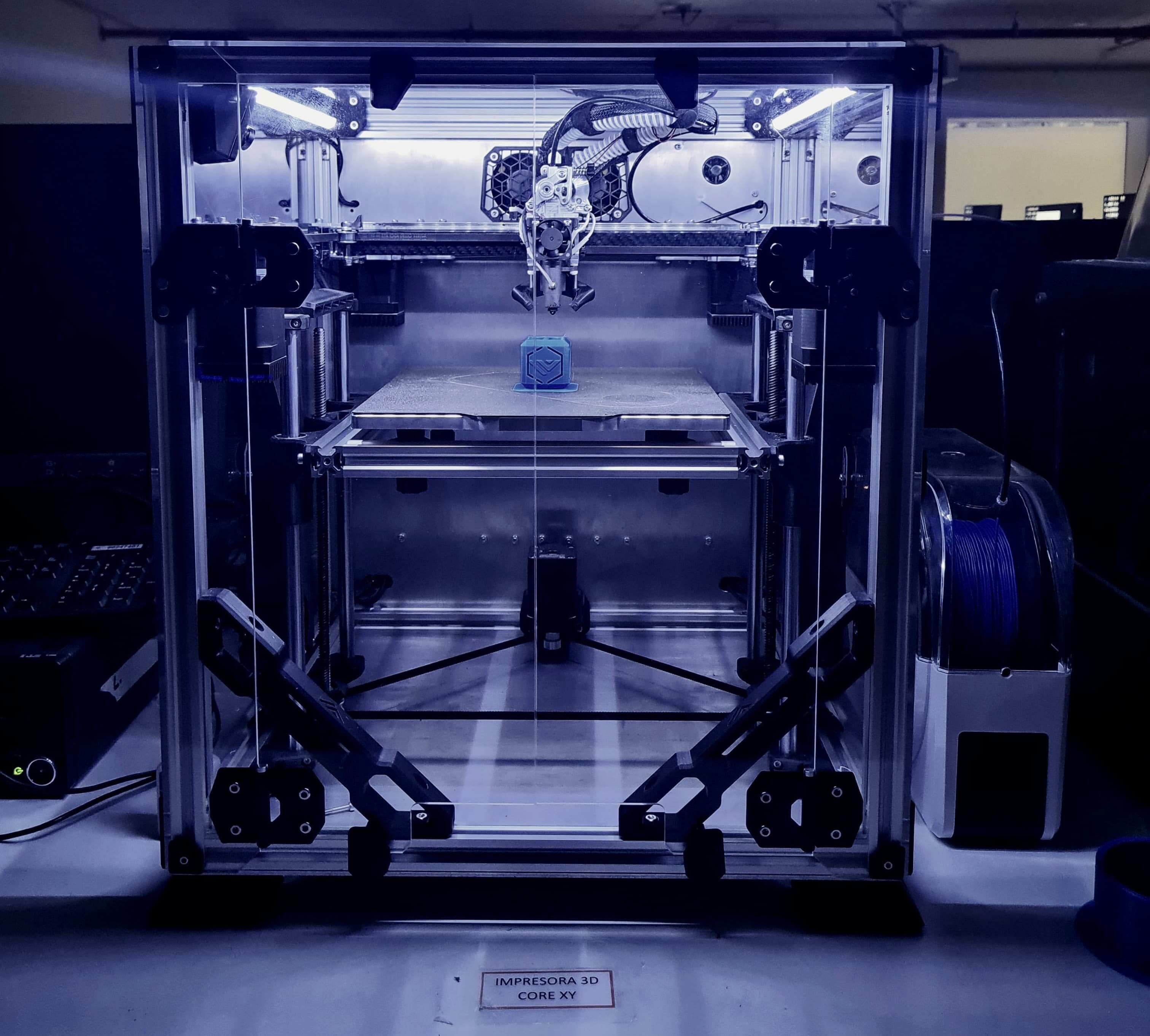
The VZBOT 235 AWD is an open-source project aiming to create a high-speed, high-quality FDM/FFF (Fused Deposition Modeling / Fused Filament Fabrication) 3D printer. These printers work by melting thermoplastic filament and extruding it layer by layer onto a build platform according to a digital design. This layer-by-layer approach allows for intricate and complex geometries to be realized with precision. The Custom VZBOT235 machine supports various thermoplastic materials including PLA, ABS, PETG, TPU, TPE, PA, PC, PP, among others, as well as reinforced materials with carbon fiber (CF) and glass fiber (GF).
Fused Deposition Modeling 3D printers are popular for their versatility and accessibility in creating three-dimensional objects. They are celebrated for their affordability, ease of use, and wide range of material options, making them suitable for hobbyists, educators, and professionals alike. Their capability to produce functional prototypes, artistic creations, and even end-use parts underscores their appeal in various industries, from engineering and manufacturing to art and design.
Depending on the operational temperature of the two main heating components, FDM printers can work with a wide range of materials. My 3D printer has a maximum rated temperature of 120°C for the build platform and 440°C for the hotend. These elevated temperatures open the door to using engineering thermoplastics with enhanced durability and stiffness, expanding the printer's capabilities for advanced applications.
3D printing stands out as the optimal choice for rapid prototyping, fast production, and iterative design processes. Unlike injection molding, which becomes costly for low batch orders due to mold expenses, 3D printing offers cost-effective solutions by producing high-quality parts swiftly. This technology revolutionizes product development by facilitating intricate designs with complex geometries previously unattainable through conventional means. Moreover, the ability to incorporate infill structures allows for lightweight and efficient designs, minimizing material usage while preserving mechanical strength and functionality.
The Klipper firmware, combined with Mainsail UI for control, offers advanced features like input shaper compensation and flow compensation with pressure advance.
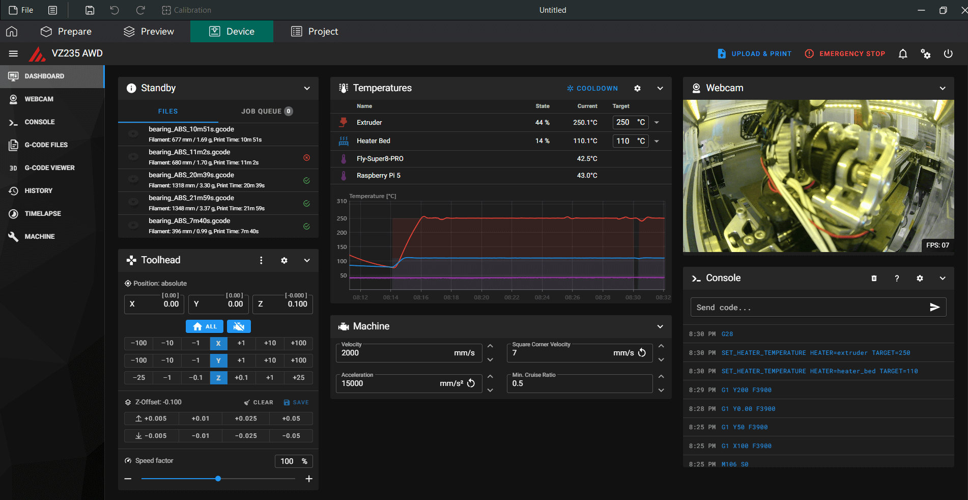
Input shaper compensation involves using an accelerometer to analyze and adjust the printer's movements. It aims to reduce vibrations and improve print quality by smoothing out any mechanical oscillations or resonances that could affect the printing process. This feature ensures that the printer moves more smoothly and accurately, especially during high-speed movements or when printing sharp corners.
Flow compensation with is another critical capability provided by this setup. Pressure advance in 3D printing serves two primary functions: it reduces ooze during non-extrude moves and minimizes blobbing during cornering. The reduction of blobbing during cornering is particularly valuable because it ensures that the printer maintains clean and precise edges on printed objects, enhancing overall print quality.
To calibrate pressure advance effectively, the printer must be properly configured. The tuning process typically involves printing a test object and inspecting the results to adjust the pressure advance settings accordingly. It's important to thoroughly understand the calibration procedure before conducting the test to achieve optimal print performance.
To improve first layer adhesion, it is recommended to clean the build plate before printing. The textured PEI plate has the advantage of being sticky for thermoplastics when hot and releasing parts when cooled down. However, this adhesion is compromised if there is oil or grease on the platform. Even the oils from skin contact can prevent proper adhesion of the thermoplastic. Therefore, it's recommended not to touch the PEI platform with bare hands. If contact is unavoidable, it's important to clean the surface thoroughly before each printing job to ensure optimal adhesion and print quality.
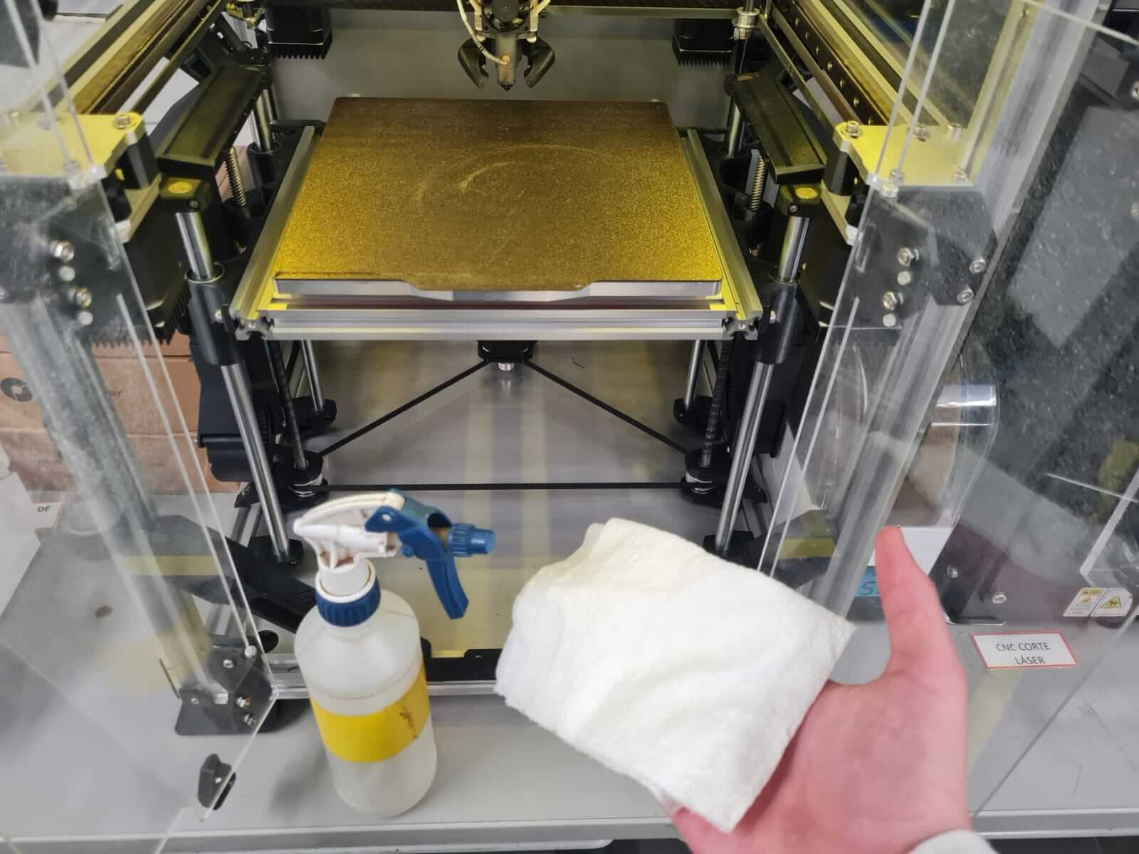
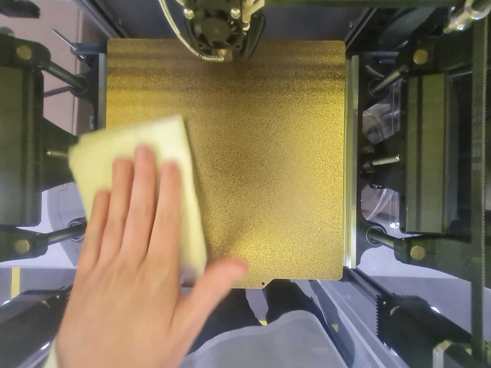
For cleaning the PEI sheet, I prefer using Ethyl Alcohol due to its lower toxicity, milder odor, and gentler effect on the skin compared to isopropyl alcohol. Ethyl alcohol is safer for use in enclosed spaces where ventilation may be limited. These factors make ethyl alcohol a preferred choice for ensuring user safety and comfort during cleaning procedures.
Achieving a perfect first layer is essential for achieving high-quality prints. In my setup, I first manually level the bed using a macro that positions the nozzle above each adjustment point until the platform is completely level compared to the nozzle. After leveling, I verify the first layer height by printing a simple geometry like a cube with a single layer. I then remove the printed layer and measure its height with calipers to ensure it matches the slicer's specified height of 0.2mm. Another method to achieve this precision is through an ABL (Auto Bed Leveling) sensor, which creates a heightmap by measuring a grid of points on the build platform. This sensor is particularly useful for correcting twisted or deformed platforms. My build plate, machined with a Kitamura Mycenter 3XG in Alumold for enhanced thermal stability and precise flatness, ensures a perfectly level bed. Currently, I am in the process of installing a Beacon ABL Surface Scanner. This scanner uses eddy currents to perform a high-resolution mesh of the bed, capturing approximately 10,000 points for precise adjustment. It provides far greater detail compared to traditional ABL sensors that typically measure a grid of around 25 points, depending on the setup. The Beacon ABL Surface Scanner will adjust the Z offset due to thermal expansion, compensating for fluctuations in temperature to maintain consistent print quality.
High-performance plastics like ABS filament tend to have a higher coefficient of thermal expansion (CTE), necessitating a heated chamber to keep the printed part solid but expanded during manufacturing. Depending on the type of thermoplastic, it is a good practice to preheat the printer for 20 minutes before actually printing the parts. In addition, in many new printers with thick build plates, the thermistor is positioned near the silicon heater, so it takes time for the temperature to reach the surface and dissipate passively to the chamber. To accelerate this process, I turn on the Remote Static Cooling System to stabilize the temperature as quickly as possible.
The Z distance between the nozzle and the platform will change at different operational temperatures, so you must calibrate the printer at working temperature, allowing time for all the parts in the enclosure to expand.
If the enclosure is not warm enough and I start a print job, my part cooling systems, the CPAP Turbo Fan and the RSCS, will warp the printed part. I have tuned the fans to cool the plastic with a specific ambient temperature of 50°C. As a consequence, I needed to increase the fan speed to compensate for the higher ambient temperature. This procedure ensures improved layer adhesion and good overhangs. The myth that ABS doesn't need cooling is outdated; ABS does need cooling, but with higher ambient temperature air.
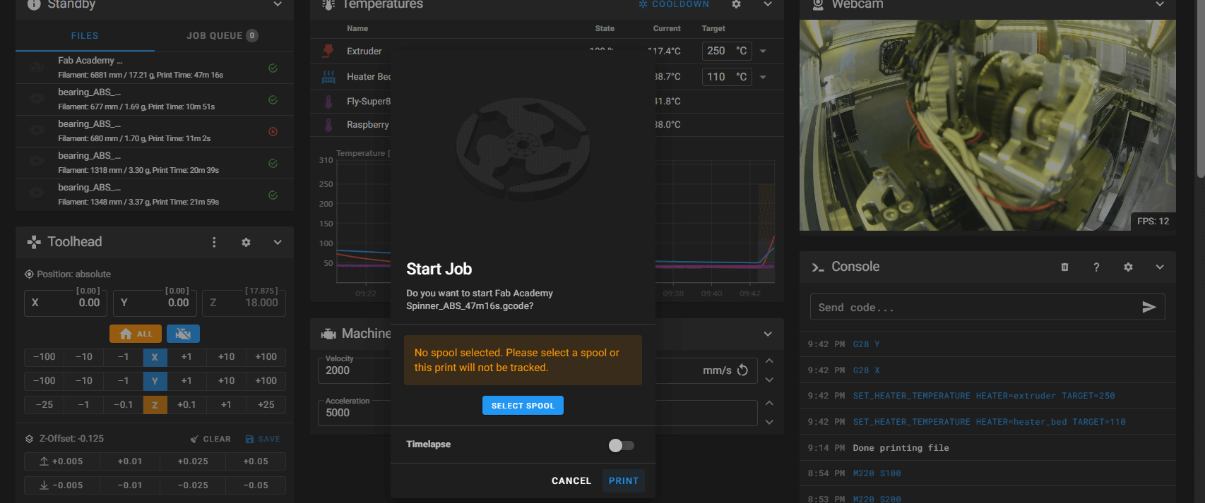
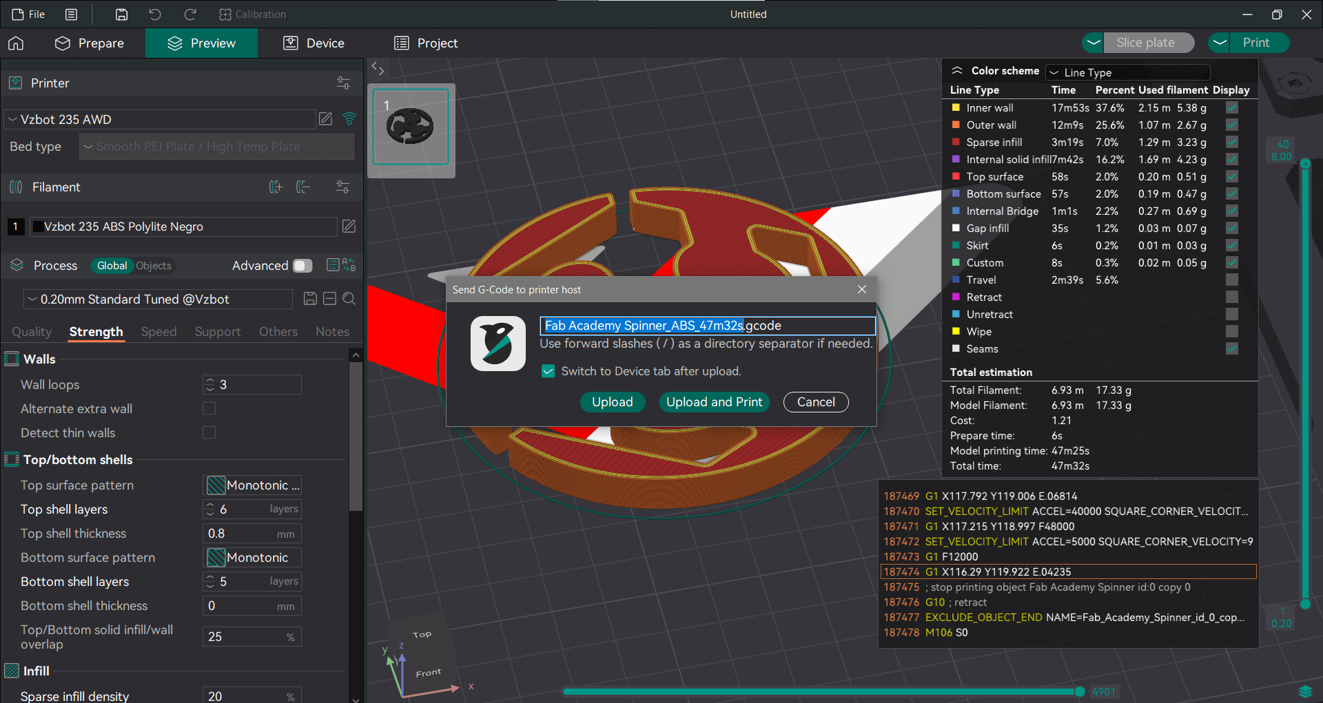
This showcases the impressive capabilities of my high precision, high-speed 3D printer. Such significant time savings are invaluable for rapid prototyping and facilitating fast iterations in my projects
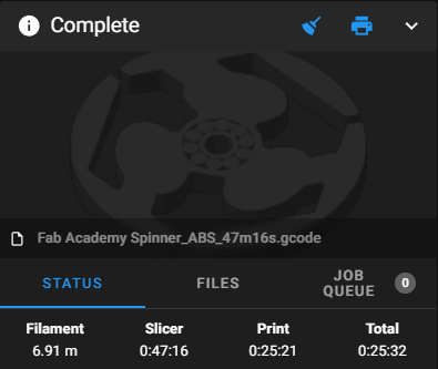
The slicer estimated a print time of 47 minutes, but the actual printing completed in just 25 minutes. This discrepancy highlights the challenge of accurate time estimation for high-speed printing. Although the Orca Slicer, a fork of the Bambu Studio Slicer, did not provide an accurate estimate, it underscores the need for more precise methods. The Annex Engineering team has developed the Klipper Estimator, designed for calculating accurate time estimations for ultra high-speed 3D printing. Such tools are essential for optimizing print schedules and enhancing efficiency in rapid prototyping and iterative design processes.
ABS thermoplastic is known to develop white stress marks. To remove these, I use an SMD soldering station as a heat gun, which effectively eliminates stress marks caused by mechanical strain.
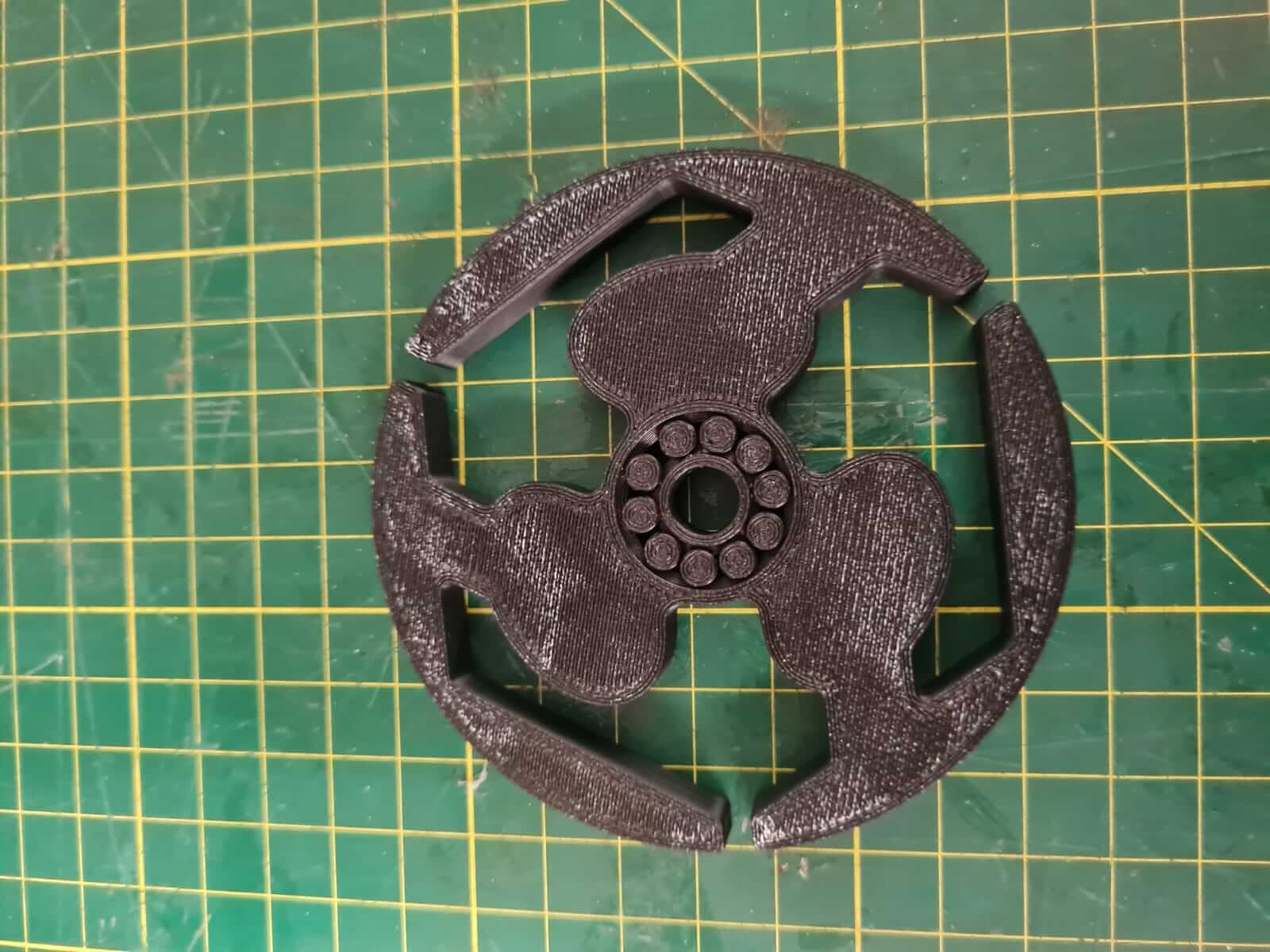
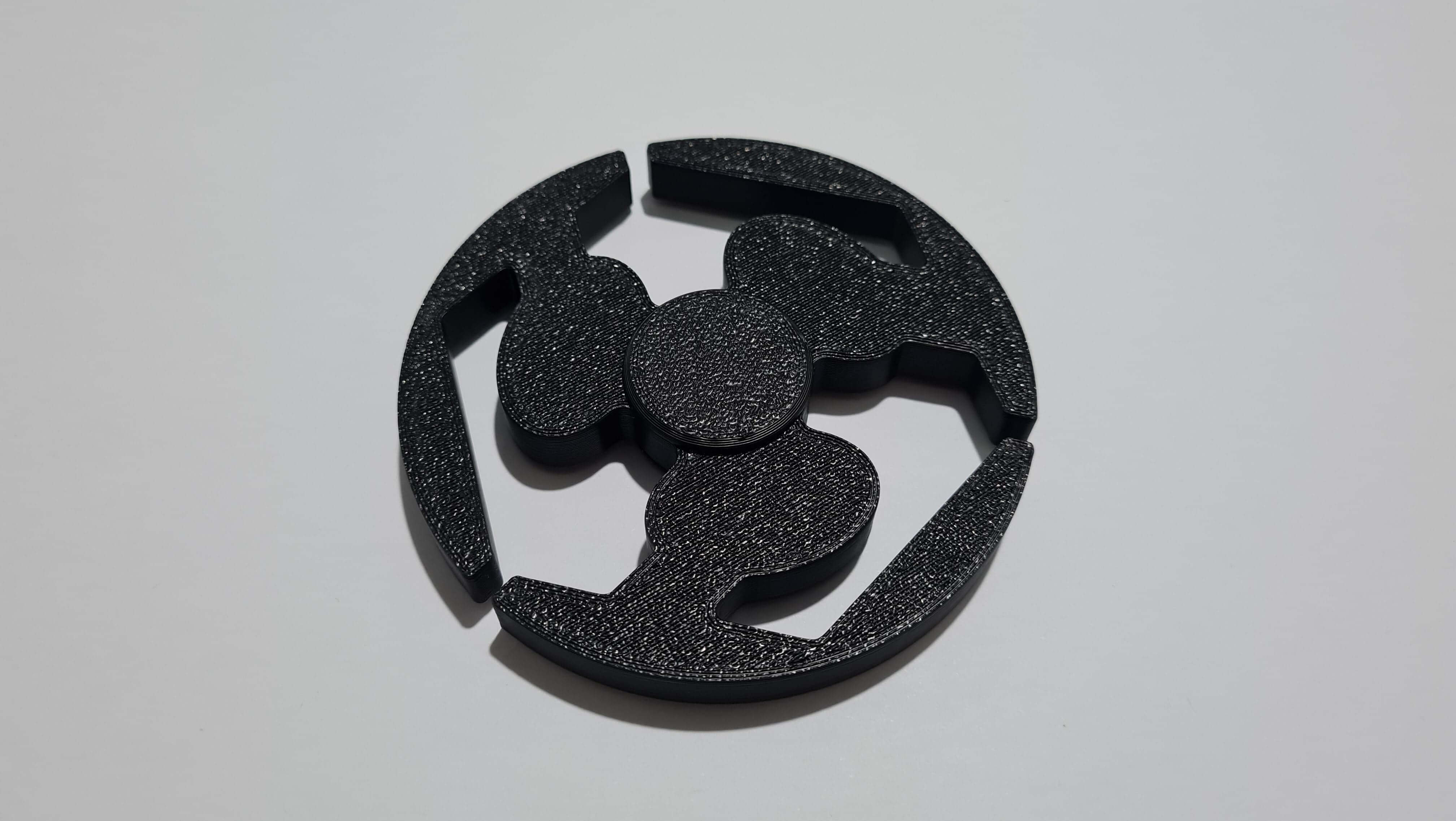
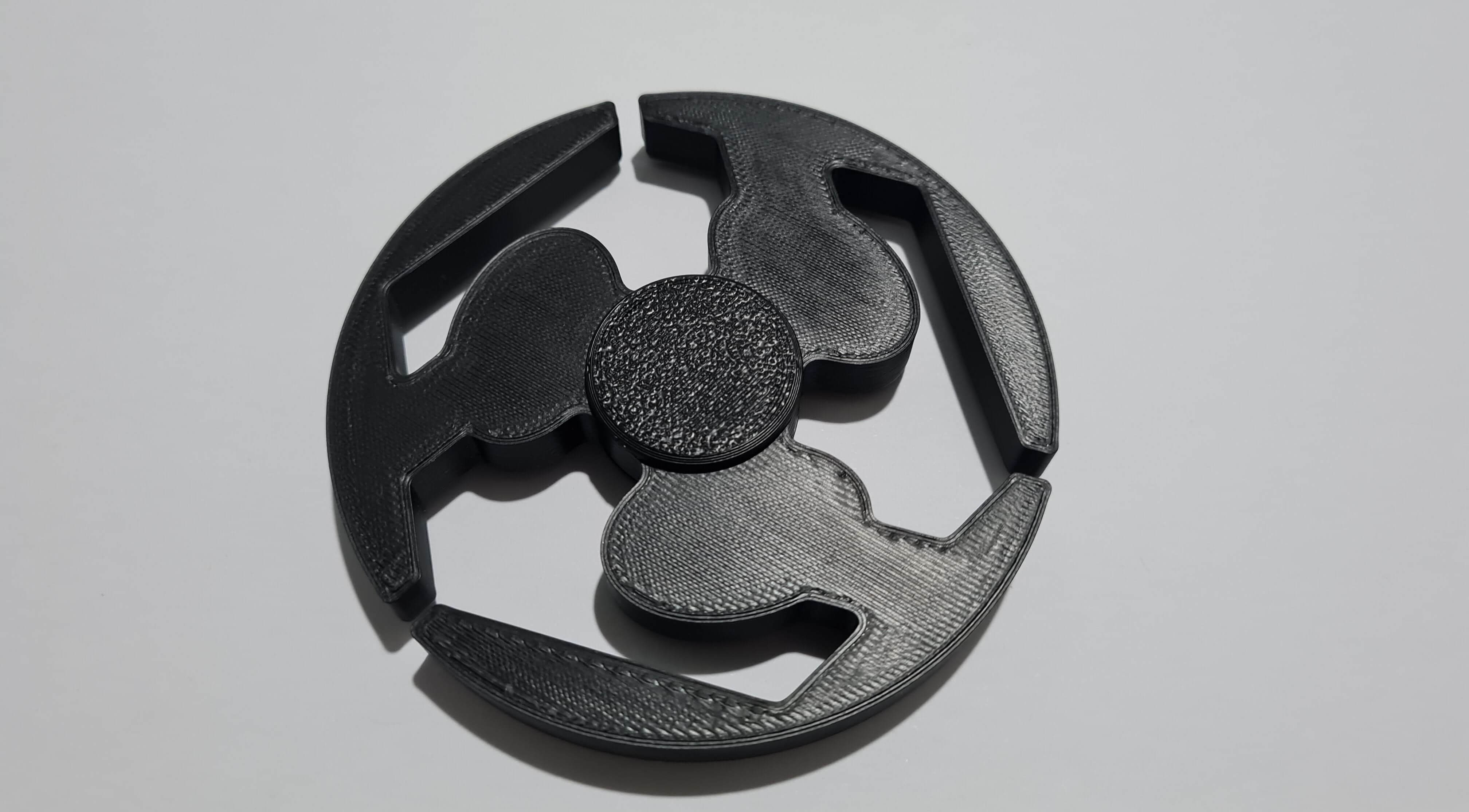
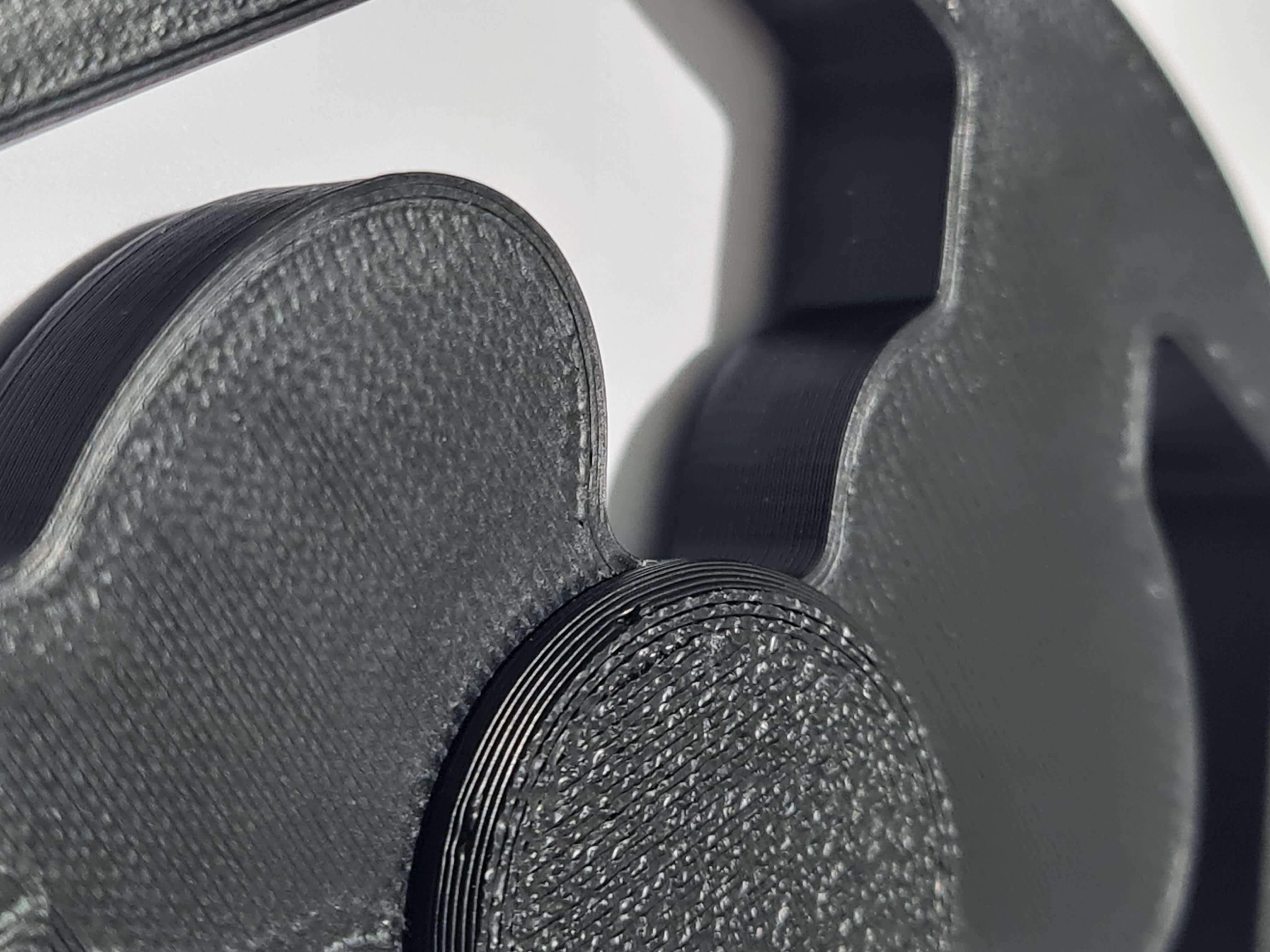
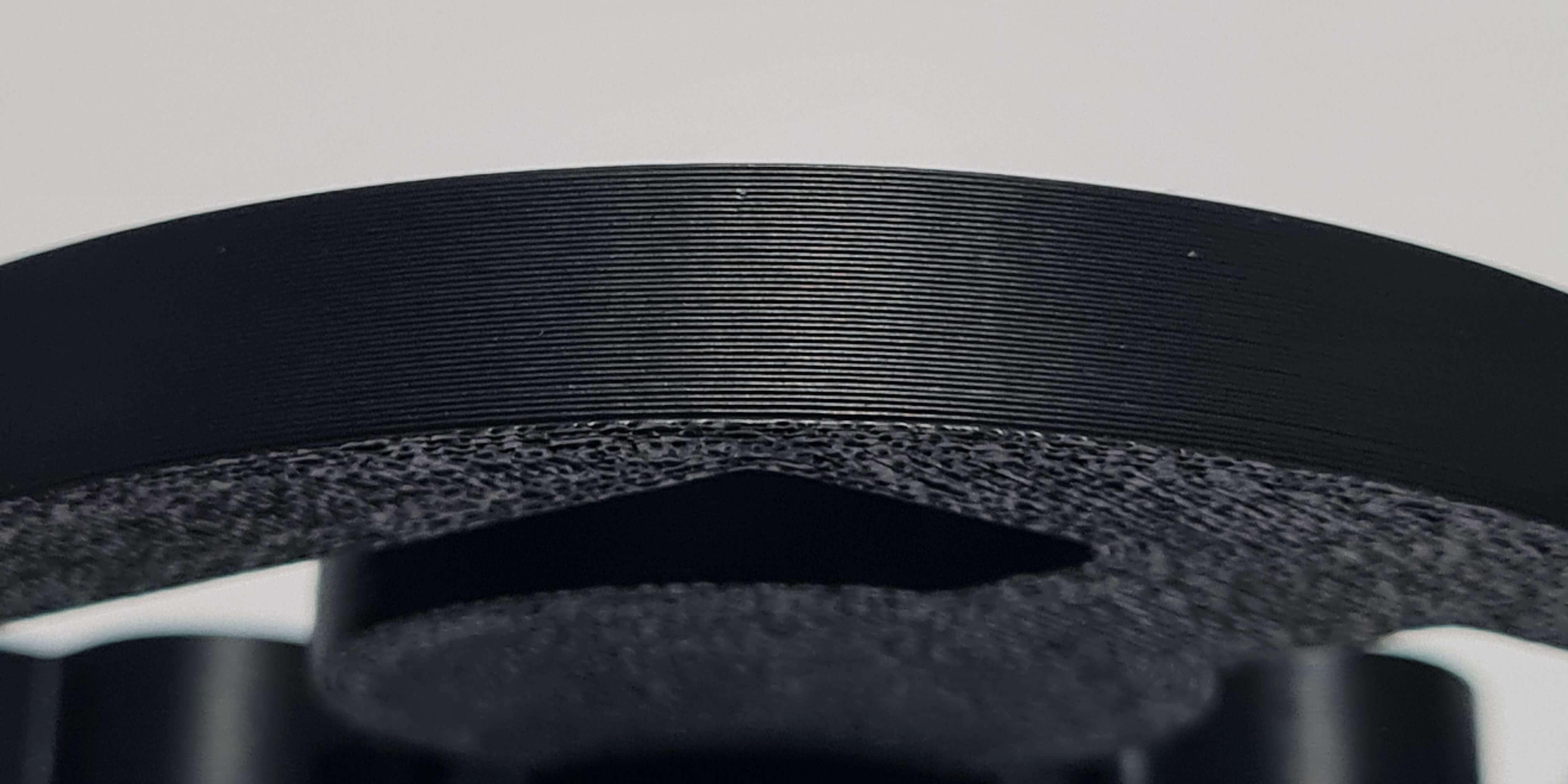
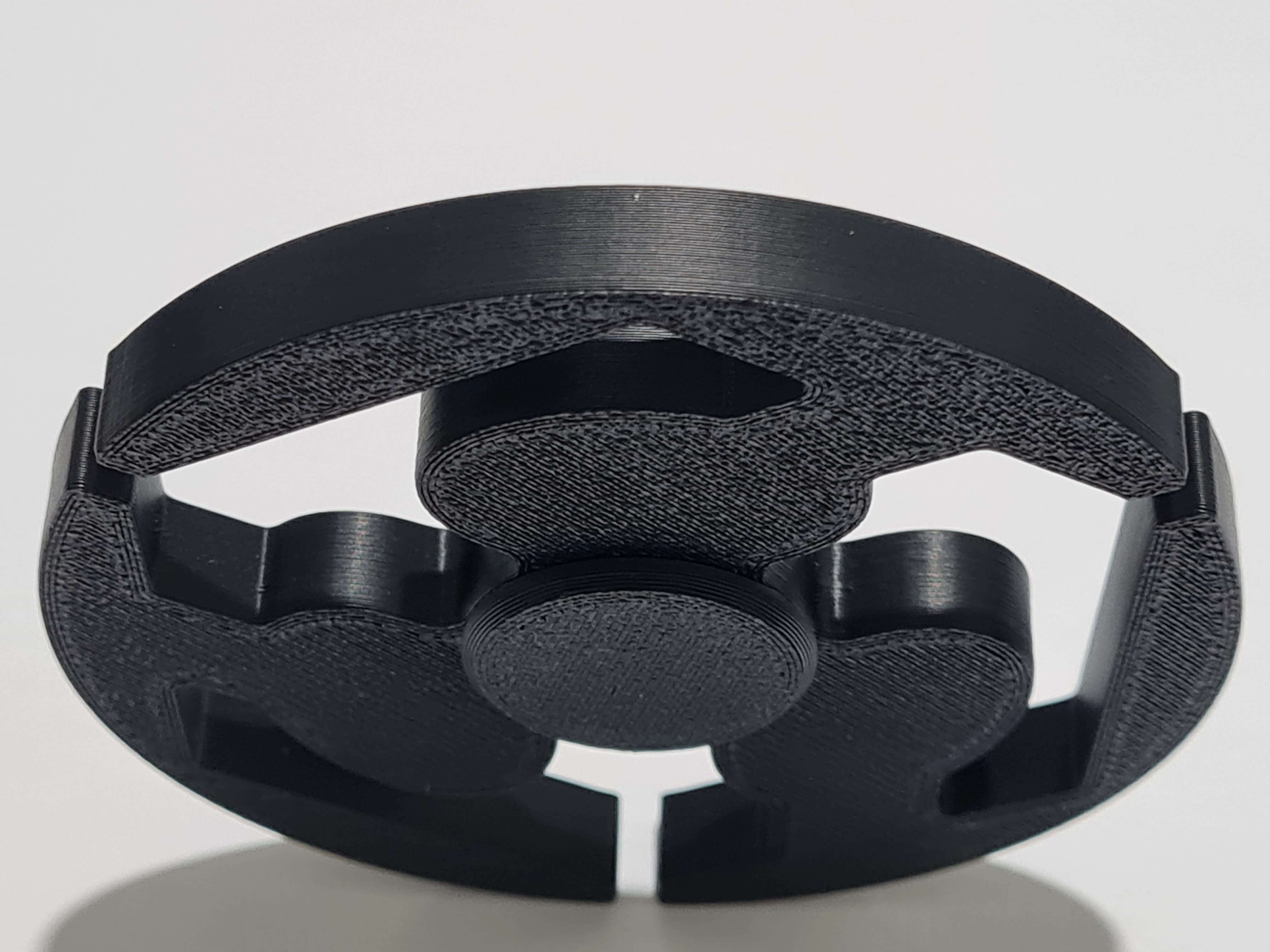
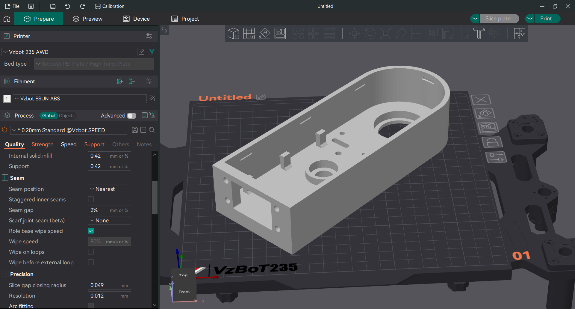
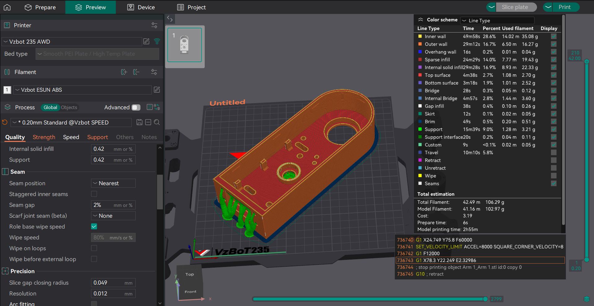
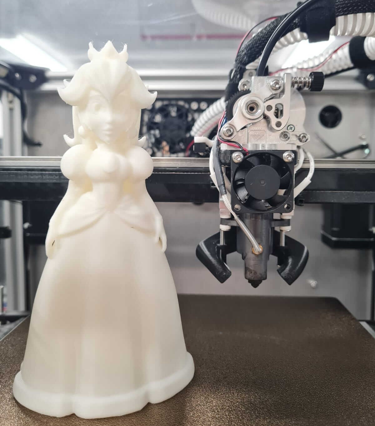
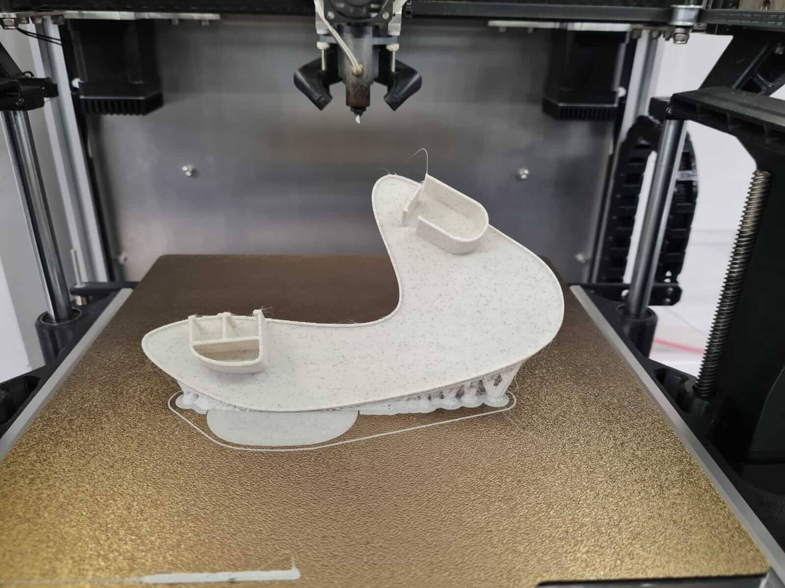
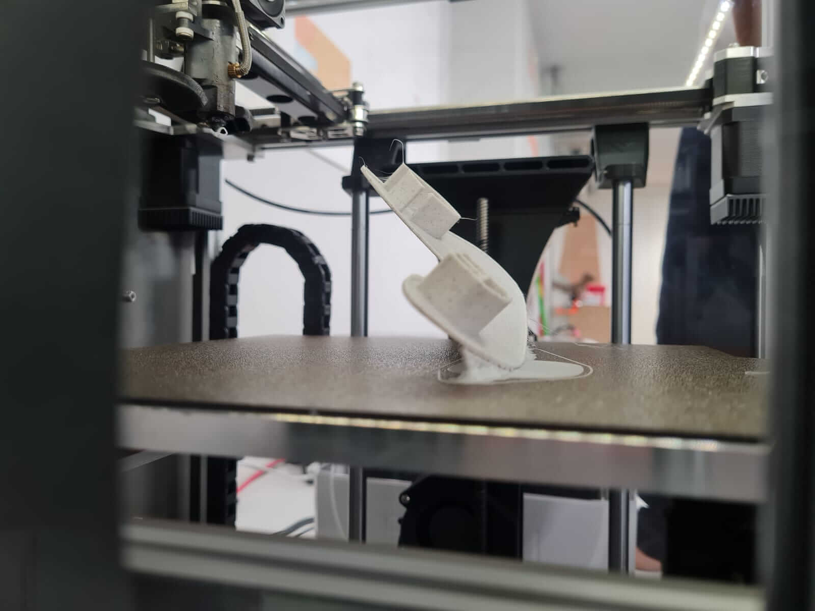
Overhangs!!!
The challenge presented by Annex Engineering, known as the #SpeedBoatRace, invites participants to print a Benchy boat model as quickly as possible using specific guidelines and rules. The aim is to push the limits of 3D printers and promote improvement within the 3D printing community. Here are the key rules for the challenge:
This competition encourages innovation, efficiency, and skill in 3D printing, pushing participants to optimize their printers and techniques to achieve the fastest and most accurate Benchy prints possible.
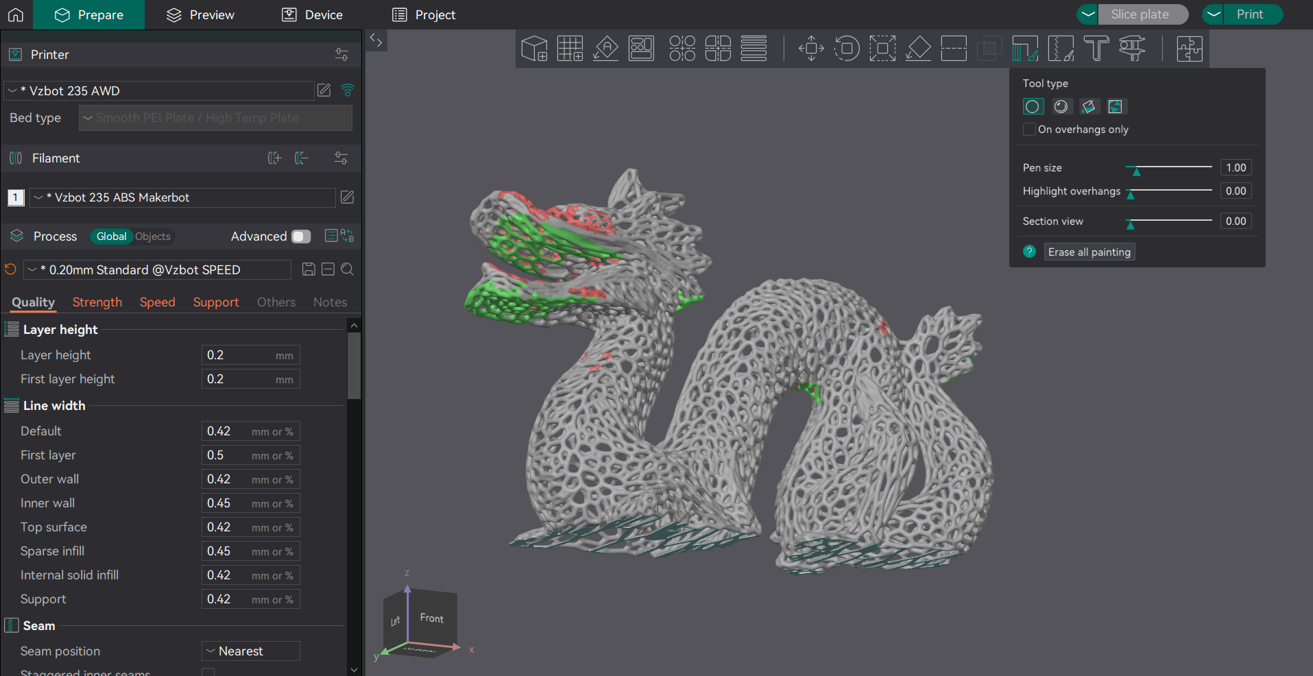
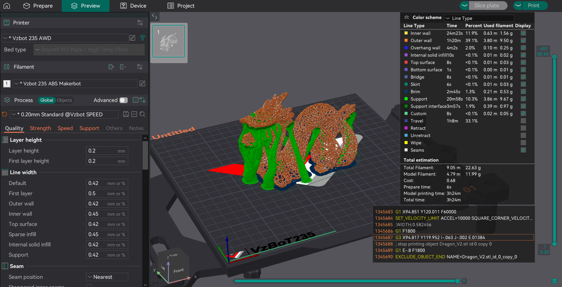
This week’s assignment involved pushing our 3D printers to the limit by printing a stress test Voronoi dragon. Our goal was to have the prints in hand to directly compare the capabilities and quality of FDM (Fused Deposition Modeling) and SLA (Stereolithography) technologies.
This week's groupal assigment we decided to print a Voronoi Dragon from www.Printables.com as a stress test for the 3D printers on the Fab Lab.
As the person in charge of FDM 3D printing, I conducted tests using both the Bambulab X1C and custom Vzbot235AWD 3D printers. These tests involved a torture model designed to evaluate retraction capabilities and the precision of material deposition in small amounts, particularly for high-detail models. To ensure optimal results, the following steps were taken:
Understanding the strengths and limitations of each 3D printing technology is essential for choosing the right method for specific applications.
By experimenting with both FDM and SLA printers, and printing the stress test Voronoi dragon, we gained valuable insights into how different 3D printing technologies can be leveraged to optimize product quality for various applications.