Week 9 assignment: Output Devices
Summary
The goal this week is to add an output device to a microcontroller board you've designed, and program it to do something
Process
This week I have divided it into two parts:
-First I will use the board from week 8 to operate an LED diode as well as a servomotor.
-Then, I will be manufacturing another electronic board where I use other types of components to operate an electric pump. This board will be the first version of my final project.
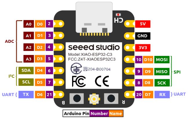
Below are the connection ports of the SAMD21 microcontroller that I will use for this week.
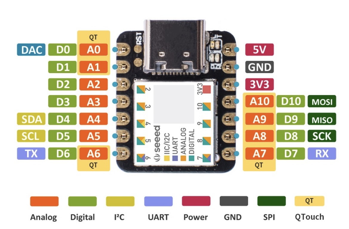
First part
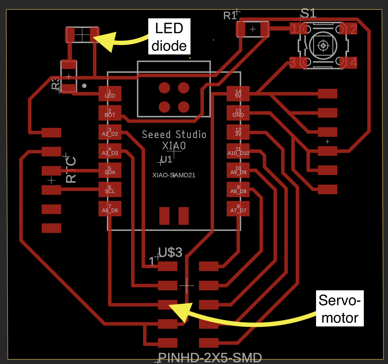
With that information, we elaborate the connection diagram of the LED diode as well as the servomotor to the SAMD21 microcontroller. The diode is connected to the first port: D0; and the servomotor will be connected to the seventh port: D6.
SMD LED diode (blue)
The colored SMD Leds are small and economical. Are perfect for use as indicators on any board, they have good stability. "SMD" stands for "Surface Mount Device." It refers to a type of technology for mounting electronic components onto printed circuit boards (PCBs).
Technical Characteristics of the colored SMD Leds:
Power dissipation: 70mW Maximum forward current: 30mA Continuous direct current: 20mA Viewing angle: 120° Strain: White: 3.0V-3.2V Red: 2.0V-2.2V Blue: 3.0V-3.2V Green: 3.0V-3.5V Yellow: 2.0V-2.2V
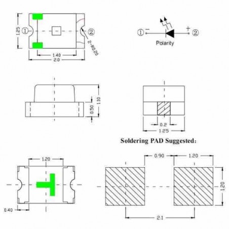
To know in which position to solder it to the board, we must respect the polarity, as shown in the following image. The long leg in the diagram must be connected to the CATHODE (negative), while the other to the ANODE (positive). This is very important for the correct functioning of the diode.
Finally, as a recommendation, it should be tested on a multimeter in the diode position with the consideration mentioned above to know which is the negative and positive terminal, and also to test if the LED is working fine.
Servomotor
This output device operates from 4.8V to 6.5V, the higher the voltage higher the torque we can have, but most commonly they are operated at +5V. In my case, I operated it with 5v delivered by the my seeeduino. it can rotate from 0° to 180° and has a torque of 2.5kg/cm. It means that the motor can pull a weight of 2.5kg when it is suspended at a distance of 1cm. It can be use as:
Robotics: To control the movement of arms, legs, joints, and other movable components.
Modeling: They are popular in RC (remote control) models to control steering, throttle, and other movements of vehicles, airplanes, and boats.
Automation: Opening and closing doors, controlling valves, and adjusting camera angles in surveillance systems.
Electronics Projects: They are widely used in common electronics projects for creating moving parts, such as opening and closing mechanisms, robotic arms, and camera pan-tilt systems.
Connecting the actuators to the board
With all this information I can now make the connections and be sure of which port to work with, where to connect the cables and the operating criteria of both actuators.
The following image shows the LED diode that was soldered to the board previously. For this consider a 1k ohm resistor to prevent the output current of the seeeduino from burning it.
You can see that along the track the current encounters resistance through the resistor and then reaches the LED diode. Finally, the circuit is closed with the ground connection.
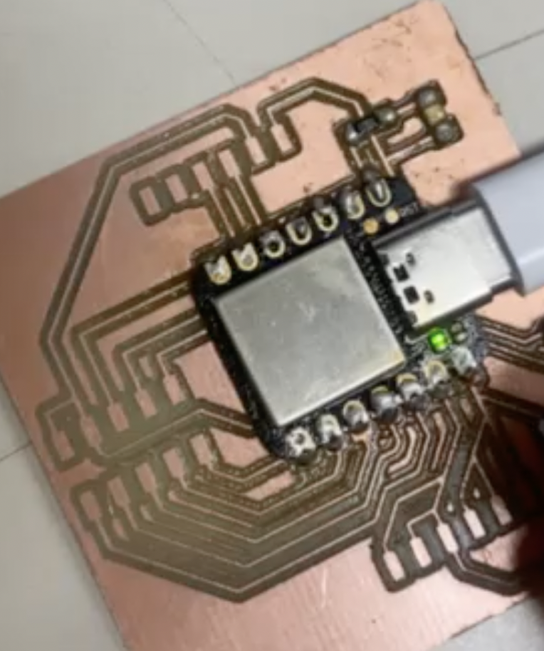
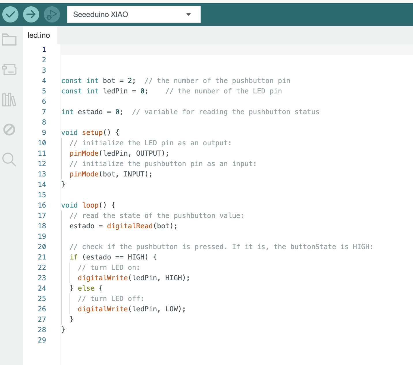
Then, the board is powered through the USB port and the LED diode is tested using a button on the board.
Finally, programming is carried out in the Arduino environment. The initial variables are declared and a variable is used that reads the state of the button. The "if" command is used to evaluate if the button is pressed, the LED turns on. Otherwise, the LED does not turn on.
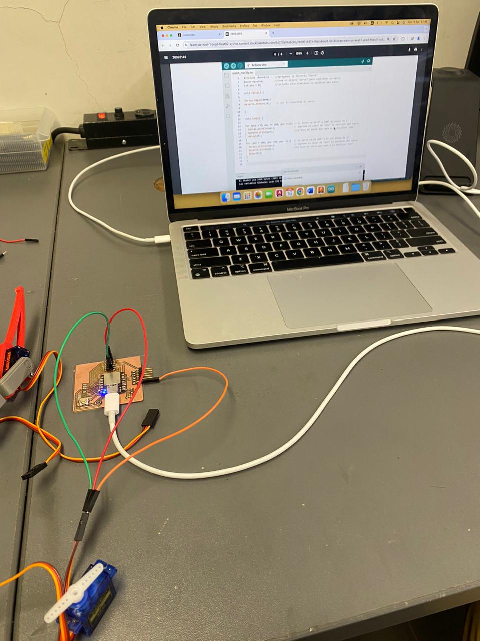
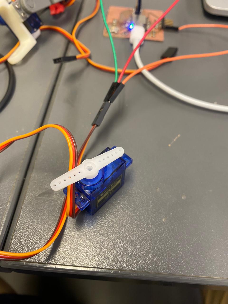
The following image shows the connection wiring of the servomotor: I used one cable to energize it with the 5v provided by the SAMD21 seeeduino, another cable to connect it to ground and another cable so that the signal that is sensed is sent to the seeeduino through pin D6.
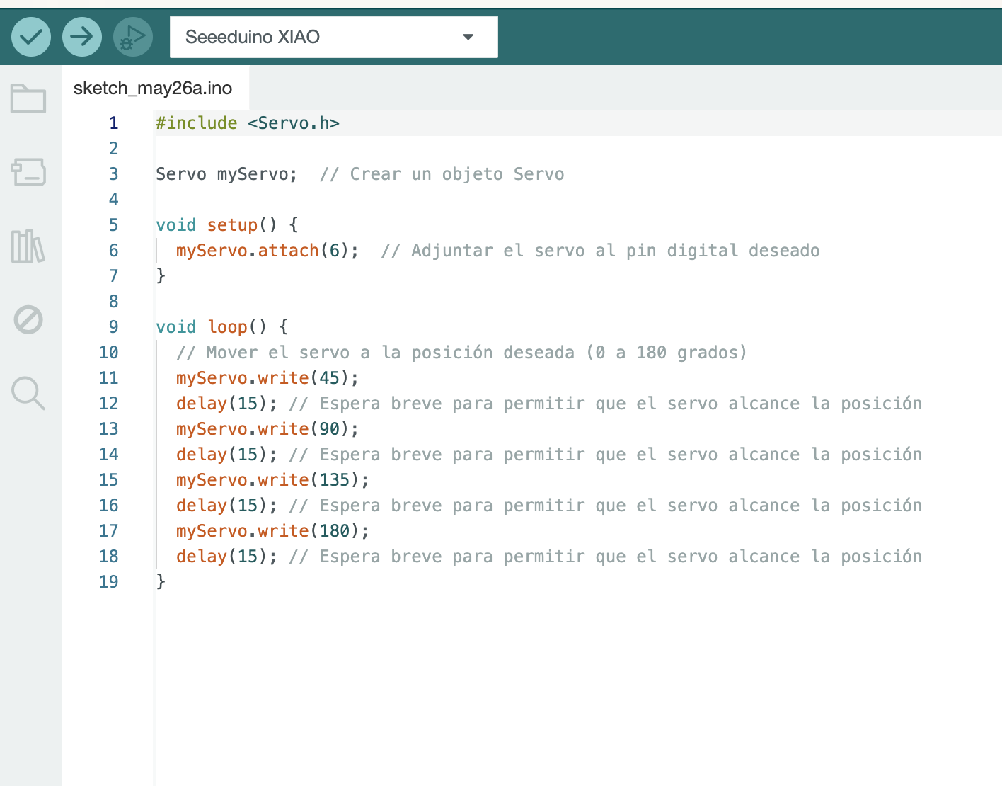
For the programming I used the "servo.h" library that is installed by default. Next, I create an object called myServo: this gives the name of the servo motor that I will use to program it later. Already in void setup, I must attach the servo to the pin I am going to use (in my example it is pin D6). Finally, in void loop I use the ".write" command to move the servomotor to the desired position which ranges from 0 to 180 degrees. I give it a small delay of 15 thousand seconds because of the delay it takes to reach that position.
Second part
As I mentioned previously, for this second part I have designed, manufactured, soldered smd and connected an electric pump to begin testing my final project.
This electric pump consumes 12v, something important to take into account for the design of its board and operation
PCB design
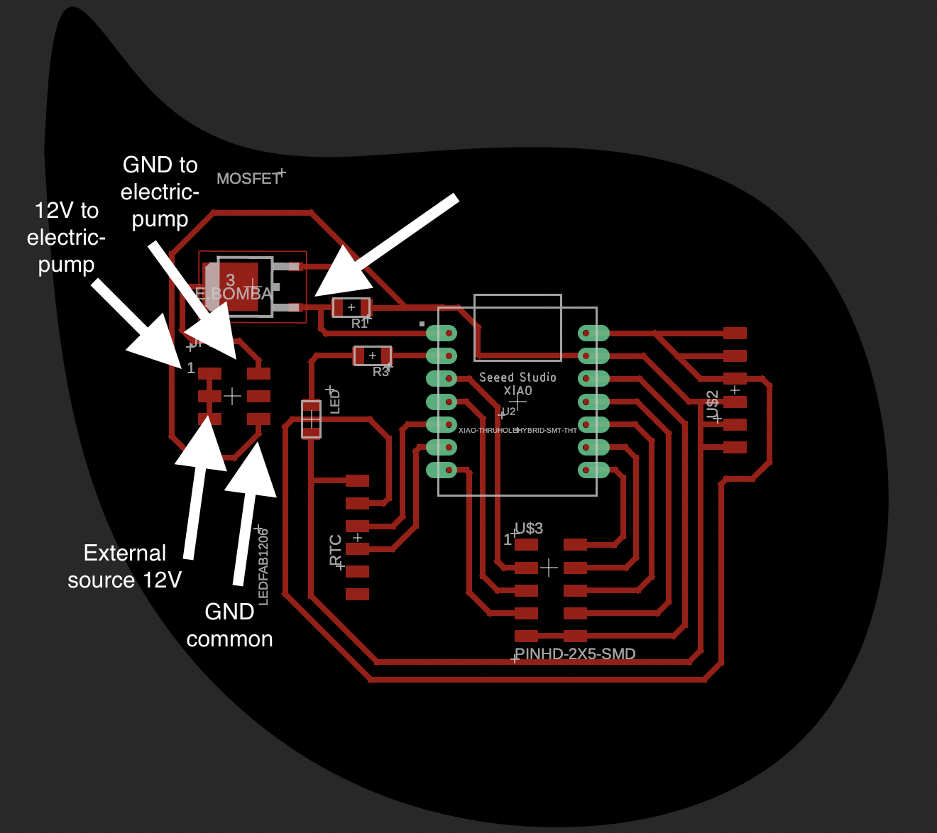
I start with the design of my board from scratch using the fusion 360 software. In the schematic part I have decided to place a MOSFET to be able to use my electric pump that consumes 12v.
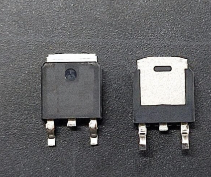
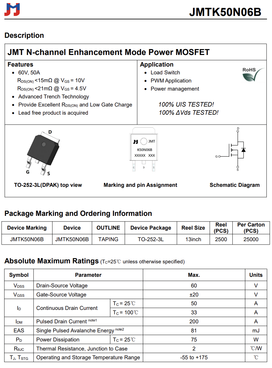
I used a MOSFET (Metal-Oxide-Semiconductor Field-Effect Transistor) 60V,50A max to control the current flowing through my electric pump.
The MOSFET acts as a voltage-controlled switch. When an appropriate voltage (through a control signal from a digital output pin of my SAMD21 OF 3.3V) is applied to the MOSFET's gate, it changes its conducting state, allowing or interrupting the flow of current between its source and drain terminals.
This mosfet must work with a resistance of 1k ohm between its positive and negative connection for correct operation.
Additionally, I designed the board with an LED and its respective resistor to do simple tests, and finally header pins to connect other sensors or actuators that I may need in the future.

This means that I will need an external 12 volt source to power my electric pump, which I will be able to control its power using PWM (Pulse Width Modulation) in programming through the MOSFET.
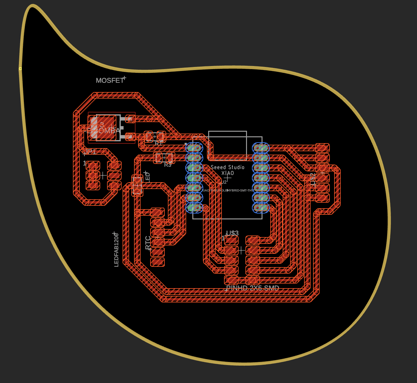
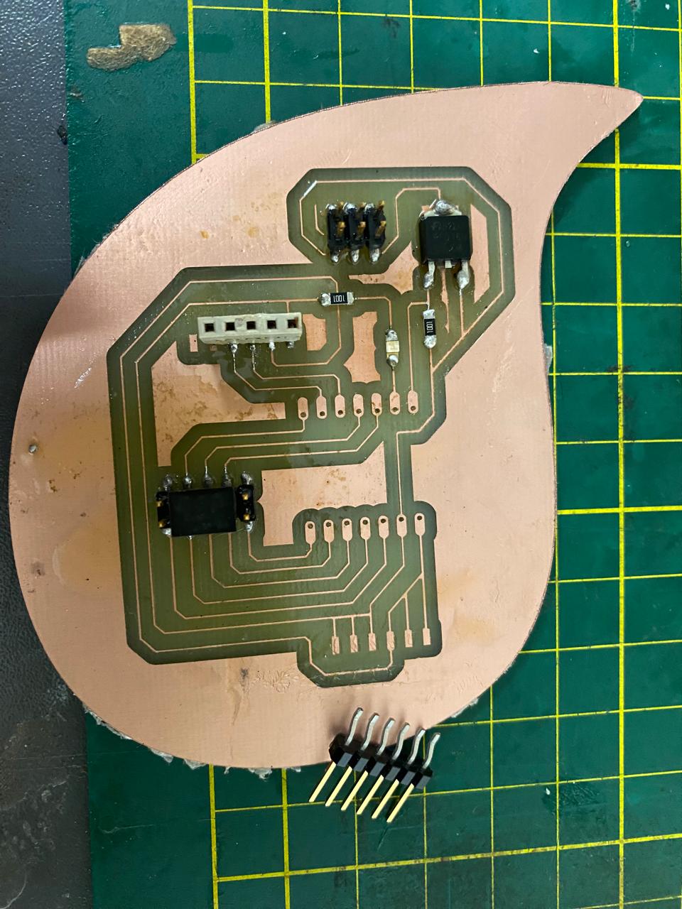
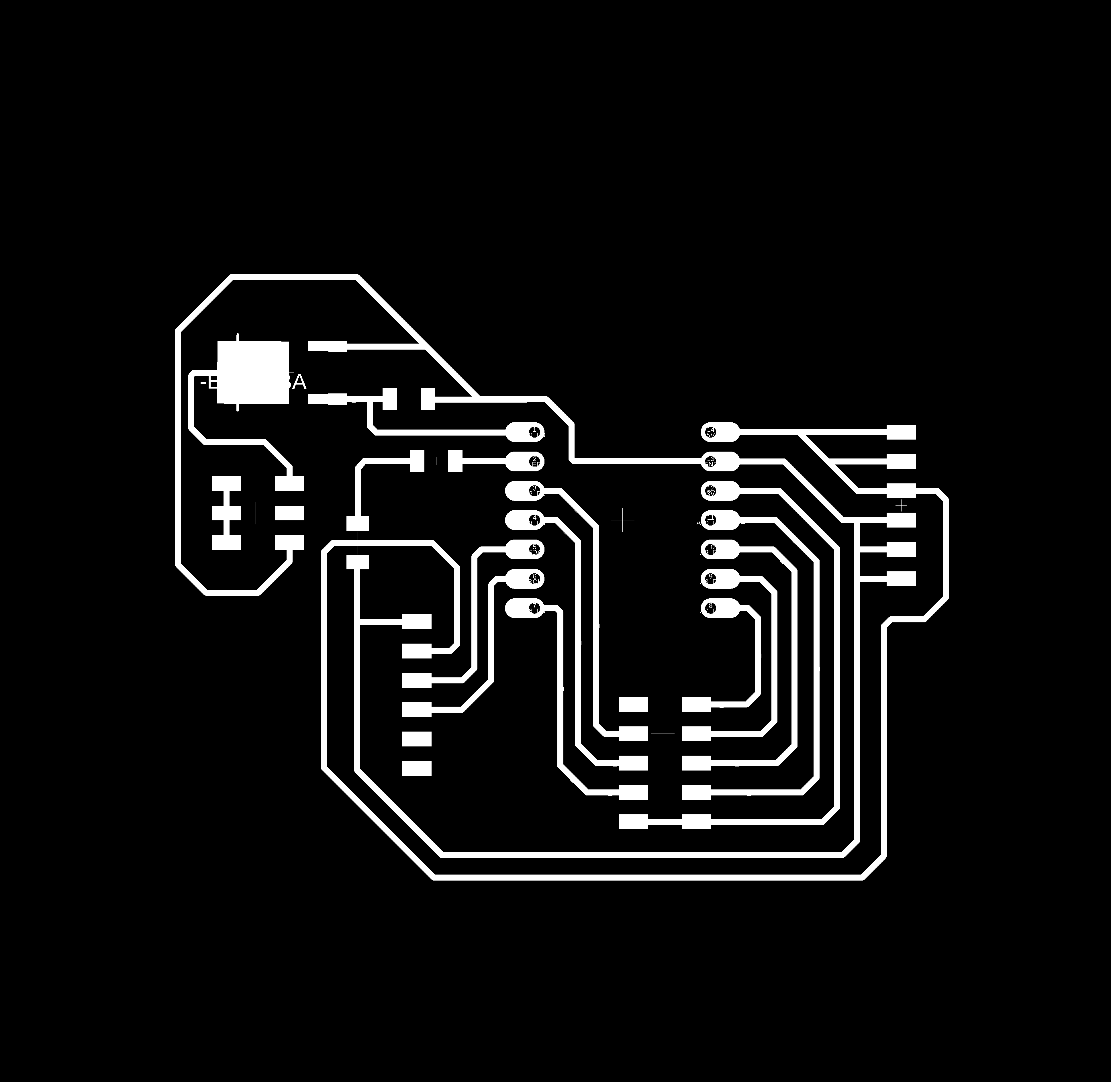
Once the design is done in the schematic, I move on to designing the tracks and the outline. I must admit that for the first board I made, it seemed a little tedious to connect the pads of each of the components with their respective connections. In this last plate it seemed simpler to me.
The trace width I used was 20 mil. In Fusion 360 or PCB design, "20 mil" refers to a unit of measurement for distances, particularly for specifying the width of traces, the spacing between traces, or the diameter of vias or pads on a printed circuit board (PCB).
In this context, "mil" is short for "thousandth of an inch," which is equivalent to 0.001 inches. Therefore, 20 mils would be 0.020 inches.
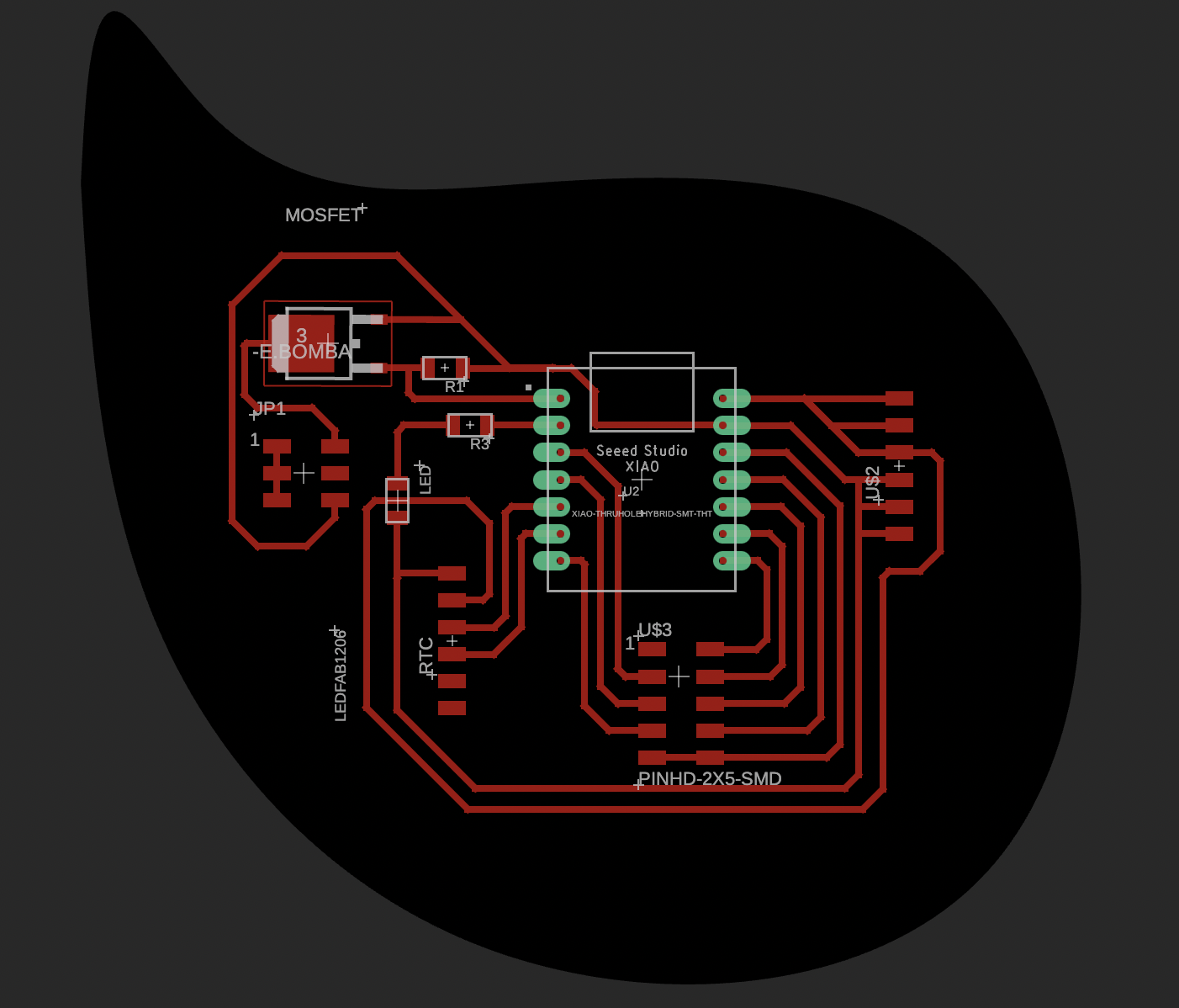
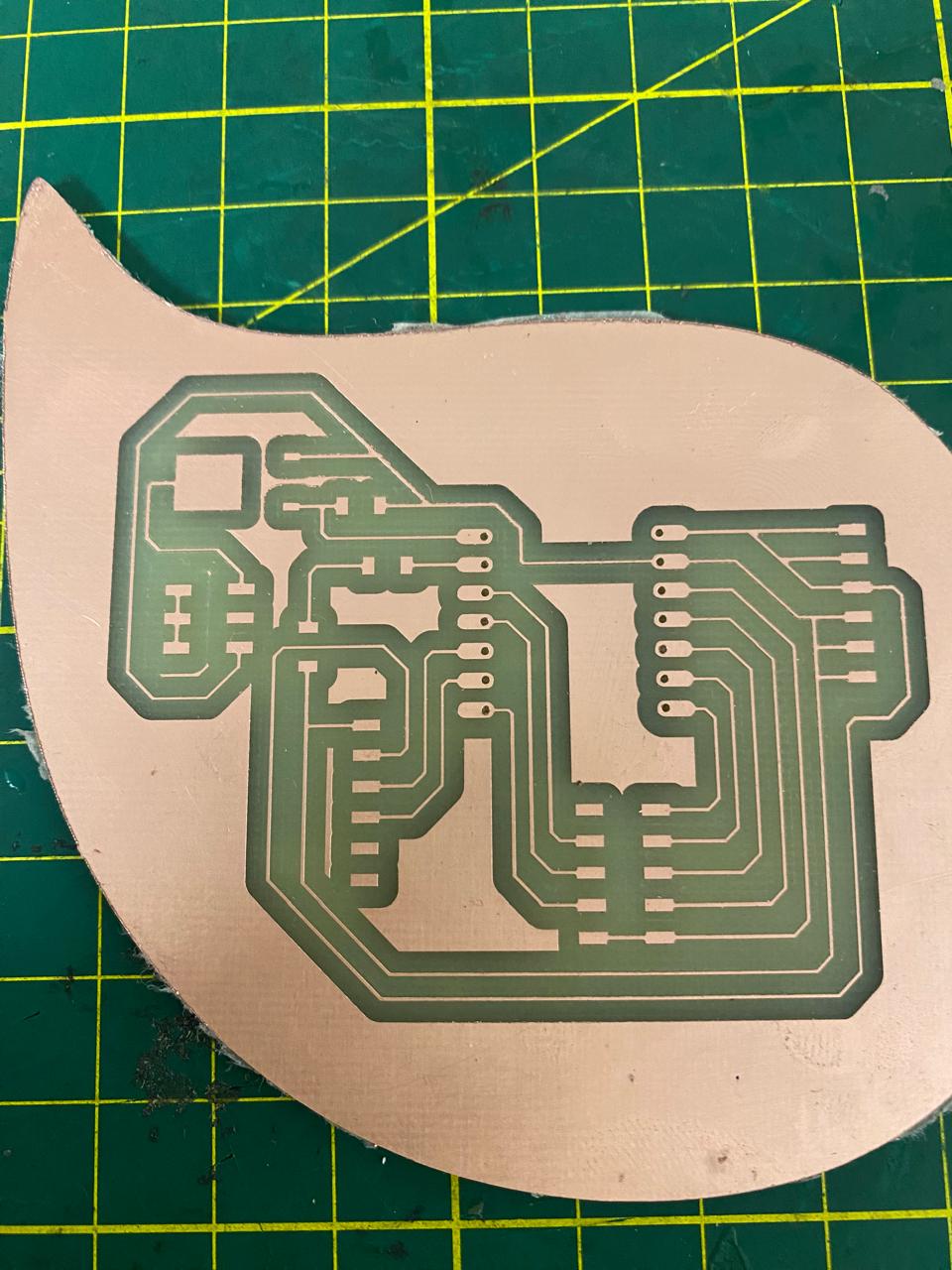
The shape of the outline that I gave to my plate corresponds to a drop, since my final project consists of a water leak detector.
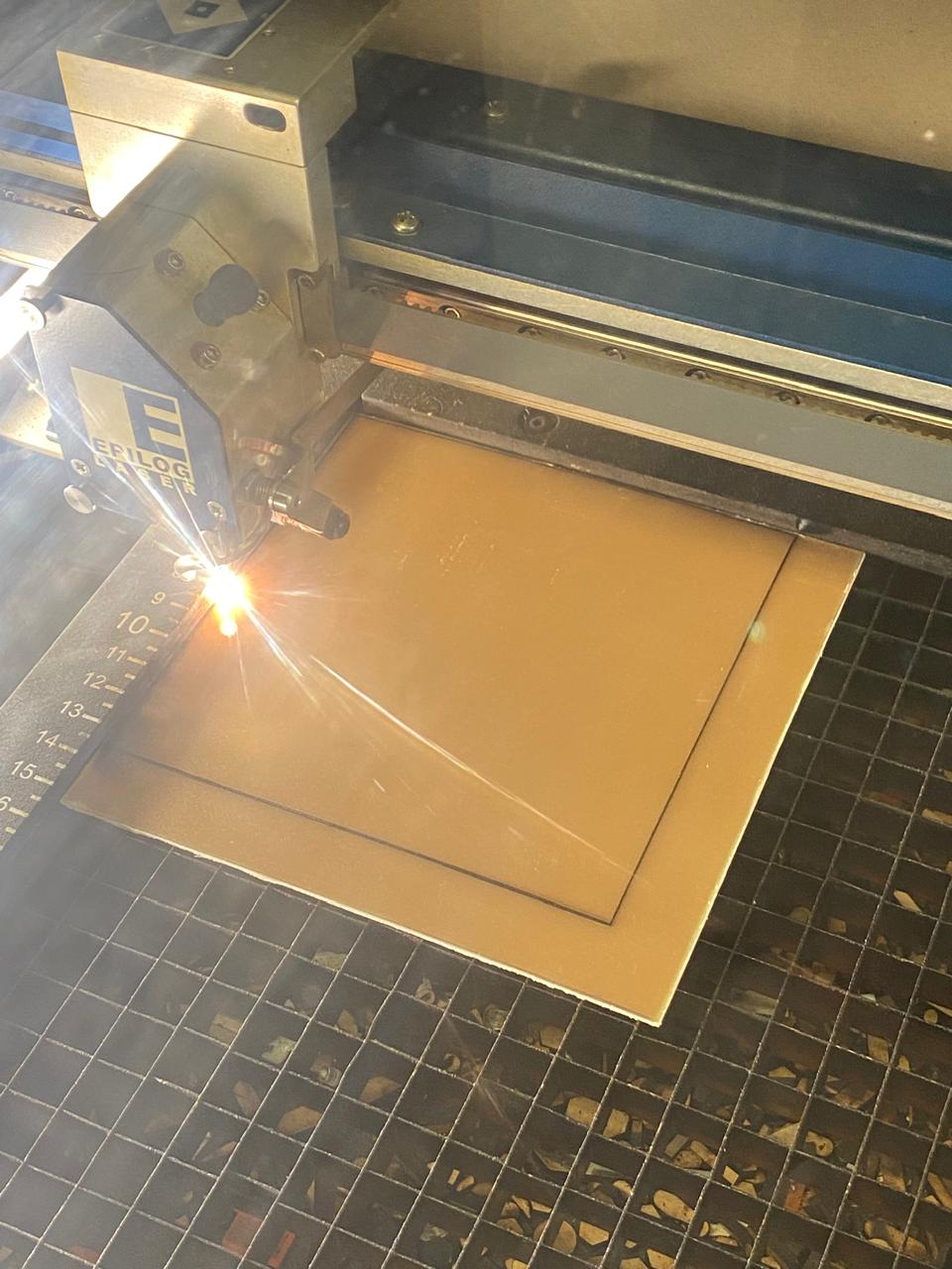
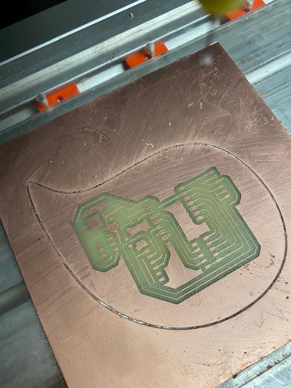
PCB manufacture
For this stage, I exported the Gerber files that Fusion 360 generated for me. I opened these files in the flatcam software to define how I am going to manufacture the plate. In this case, I continued using a 30° drill bit entering a depth of 0.1mm. Used 10 passes to have ease in SMD soldering.
Additionally, I will be making holes in this board with a 0.8mm diameter drill bit so that I can try other seeeduinos models (I plan to work with the SAMD21 and the ESP32-C3).
Finally, I made the drop-shaped contour using a 0.8mm diameter milling cutter.
PCB smd soldering
In this part I proceed to solder the SMD components to my board. The MOSFET, which is the new component that I am soldering for the first time, is simple and without any complications, since its terminals are large enough to avoid making mistakes when soldering.
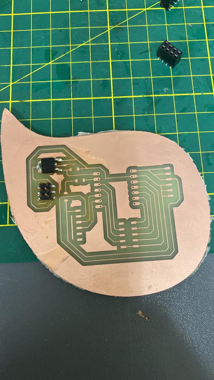
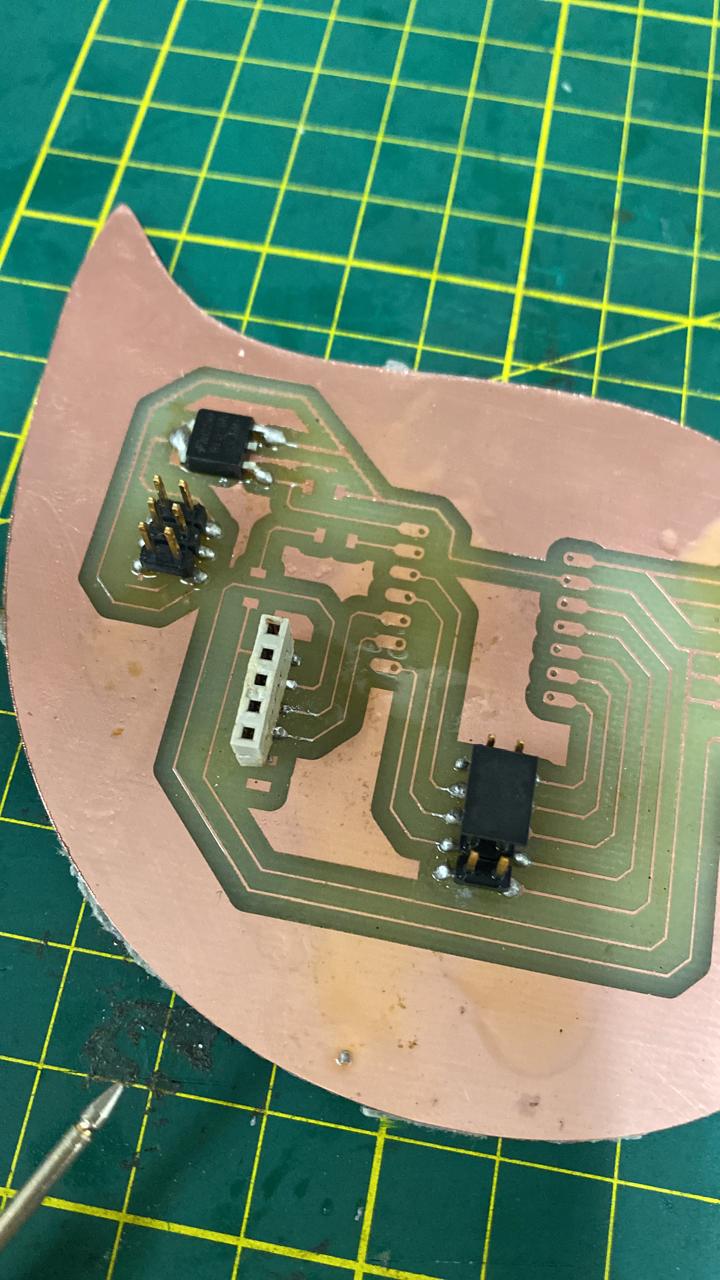
The 3x2 header pins will serve to bridge the 12 volts from my source to the positive pole of the electric pump. The other negative pole will be connected to the output of the MOSFET and will regulate its power.
Finally, I have soldered some male pins to my seeeduino and some female pins to my board, so that I can try a different microcontroller in the future. I have tested another led and so far everything good.
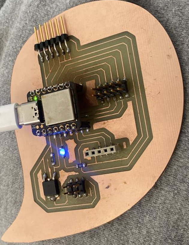
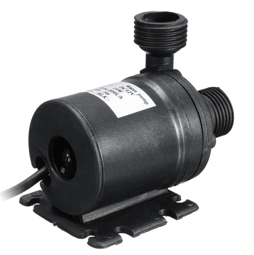
Electric pump connection & test
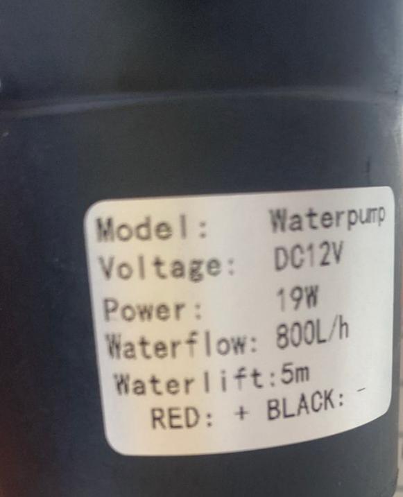
The electric pump I used is a submersible and works with 12v. Since it is submersible, I do not need to prime it beforehand. Below are some of its technical specifications:
Voltage: DC12V
Power: 19W
Maximum rated current: 1000MA
Flow rate: 800L/h(m3/h)
Maximum water elevation: 5 meters
Working environment temperature: 1-60 ℃
Maximum circulating water temperature: 100°C
Noise:< 40 dB (water) in operation
Driving mode: electromagnetic
Transport medium: hot water pump
Pump shaft position: Horizontal
Impeller structure: open impeller
Impeller suction method: a type of suction
Cable line: 500mm/19.69in
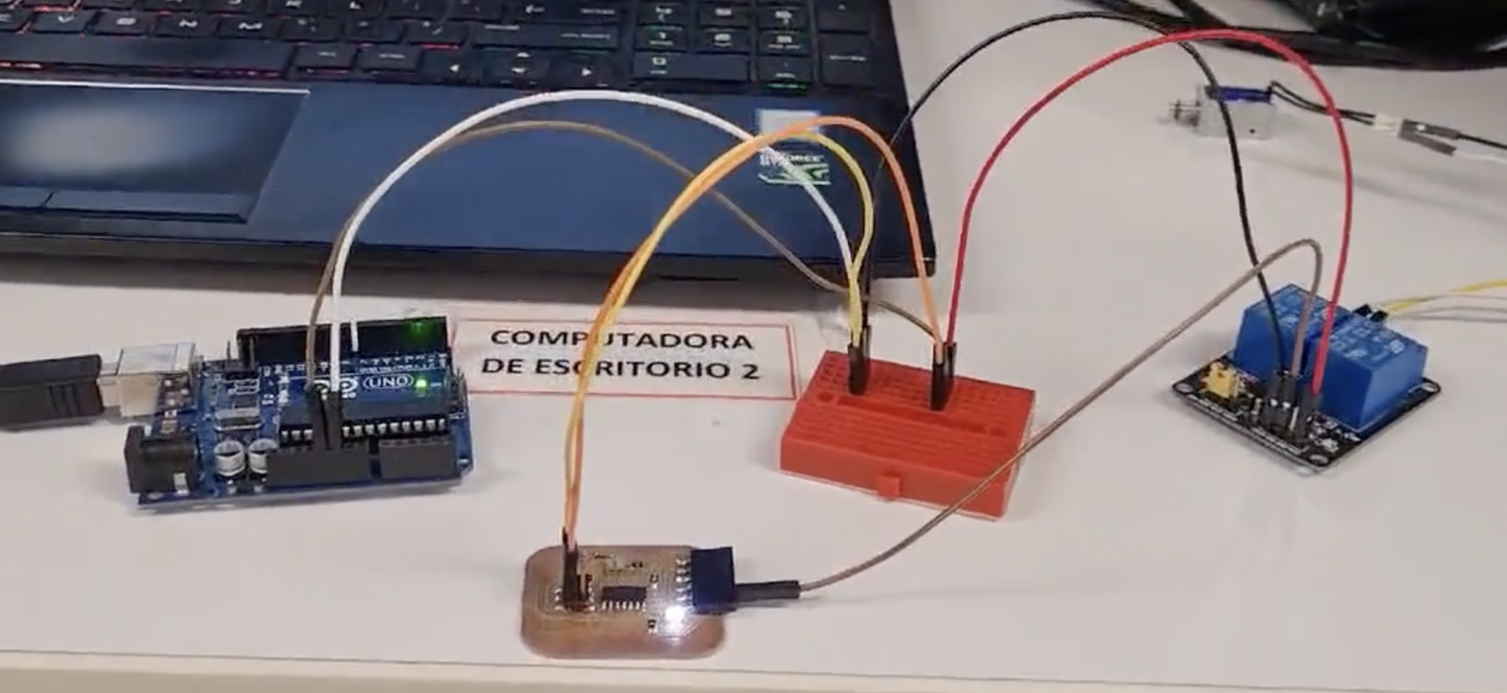
For the test, I decided to use the Seeeduino ESP32-C3 microcontroller. This is the one that I have decided to use in my final project and I will be starting to test with the one that allows working with IoT wifi connectivity.
The connection diagram of the electric pump is shown below. It must be taken into account that the negative poles of the Seeeduino ESP32-C3 microcontroller and that of the external 12V source are linked (common).
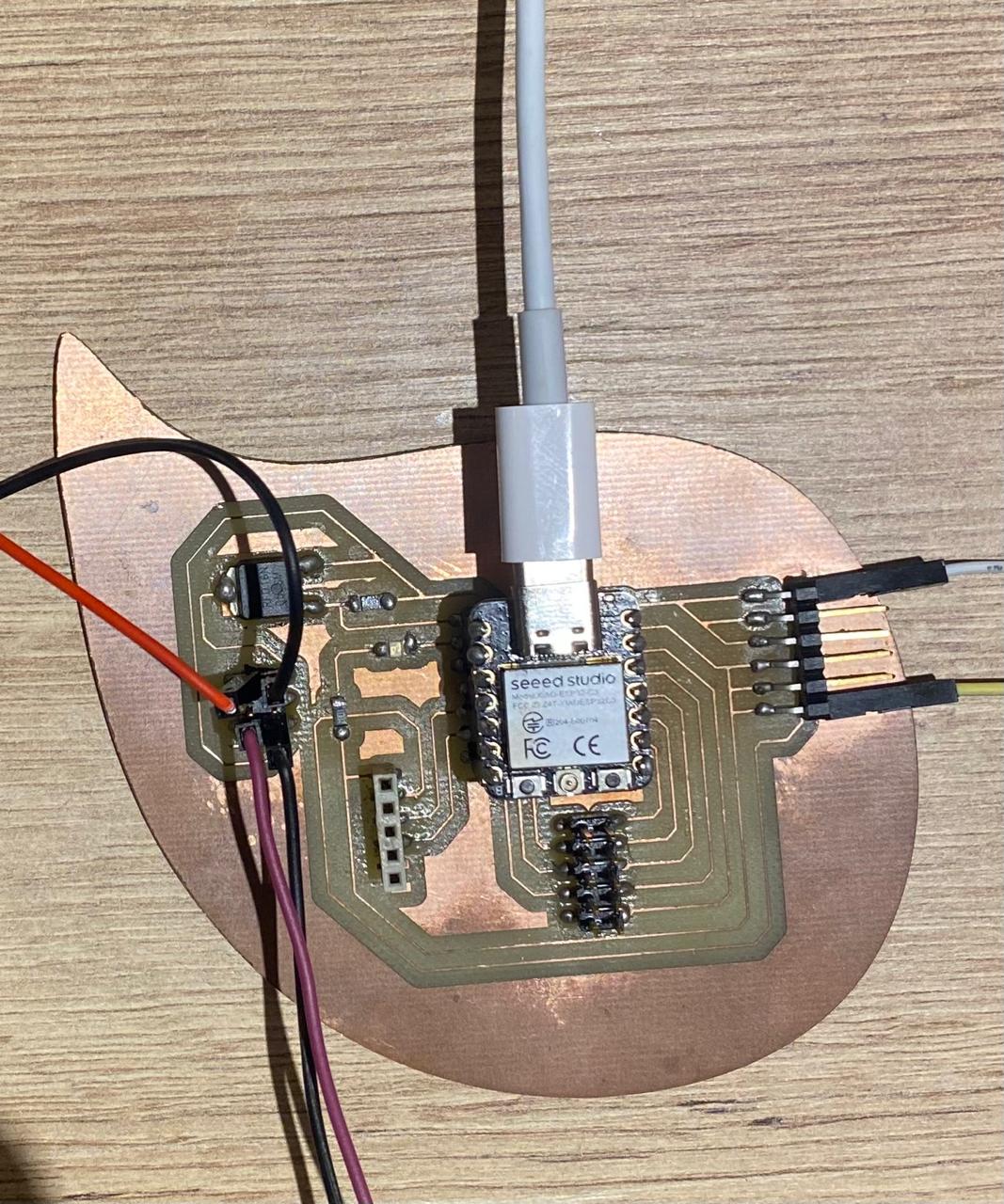
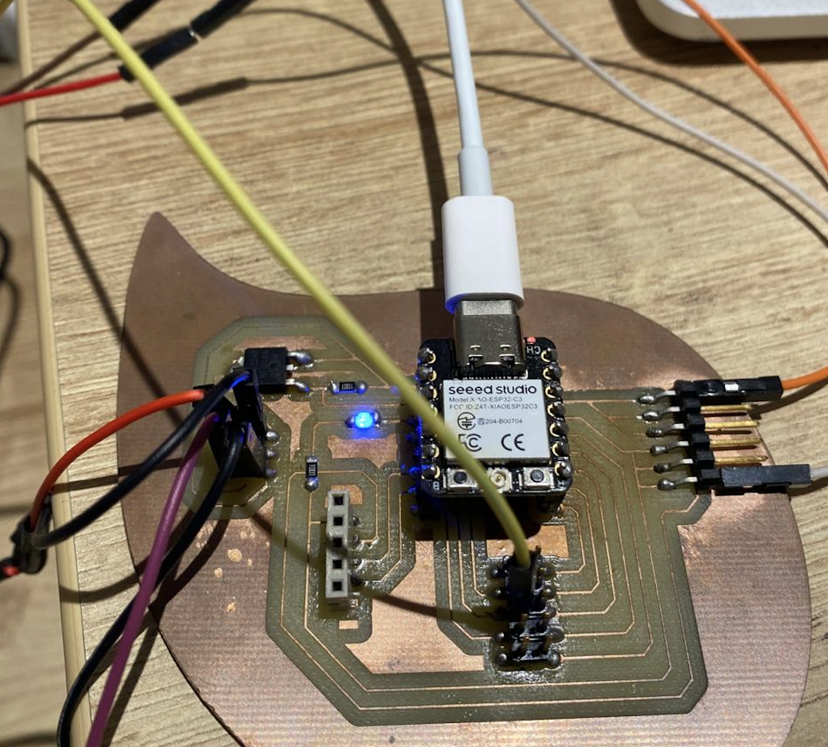
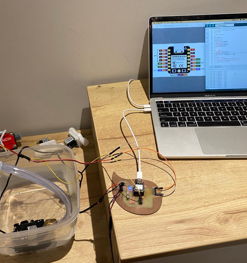
Finally, the electric pump is tested and it is verified that it works without heating the MOSFET, which indicates that it is capable of withstanding that working current.
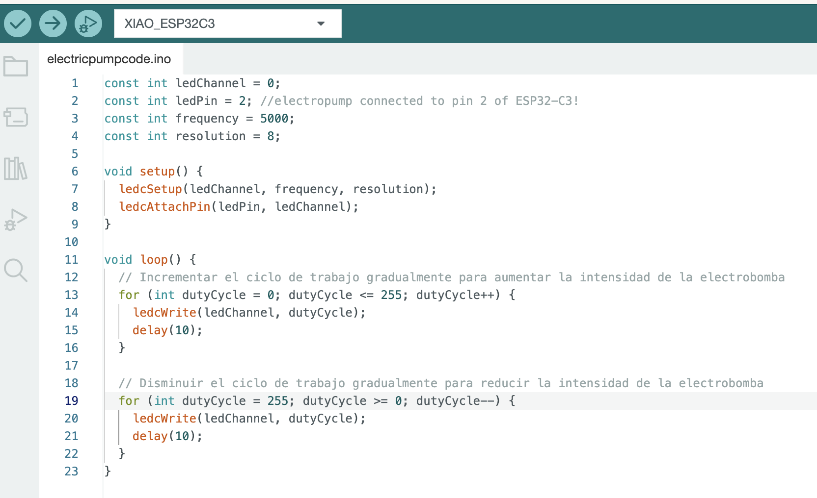
The programming code in Arduino is the following where the pump is being tested at its minimum and maximum flow rate. In week 12 (sensors), the flow rate this electric pump is delivering will be measured to ensure that it meets the minimum characteristics of a water leak, so that it can be incorporated into the final project.
"ledcWrite" is the function I use to work with PWM. It is similar to analogWrite.
Group assignment
What I learned from this group experience was how to measure the power consumption of actuator.
My contribution to the group work was to verify how we have measured the current.
Also take advantage of the fact that we can see the current consumed with which the source delivers.
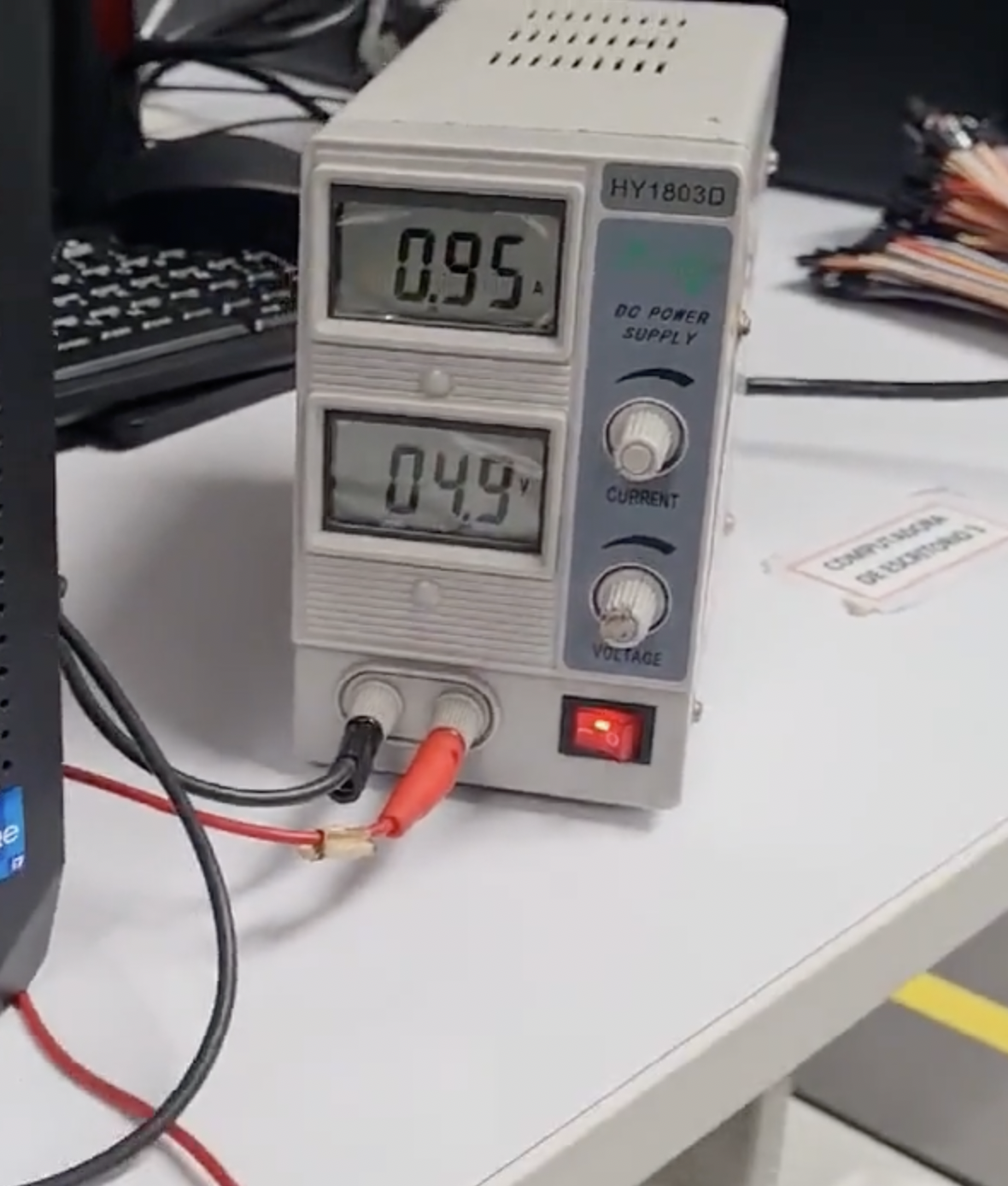
This is the connection used that goes to the source.
Here is the link to the group assignments:
Files: