Week 8 assignment: Electronics Design
Summary
The task this week is to use an EDA tool to design a development board to interact
and communicate with an embedded microcontroller,
produce it, and test it.
Process
For this week's project I decided to use Flatcam software to generate the G code of my electronic board design. Previously, in week 4 I had used MOODS online to manufacture the board, however I decided to try this week with this new software to compare the results, which I will show at the end of this documentation.
I decided to work with a seeeduino board because they can provide a platform for building and programming electronic projects.
A PCB (Printed Circuit Board) is a critical component in most electronic devices. It's a flat board made of non-conductive material, such as fiberglass or epoxy, with conductive pathways etched or printed onto it. These pathways, typically made of copper, provide connections between electronic components like resistors, capacitors, and integrated circuits.
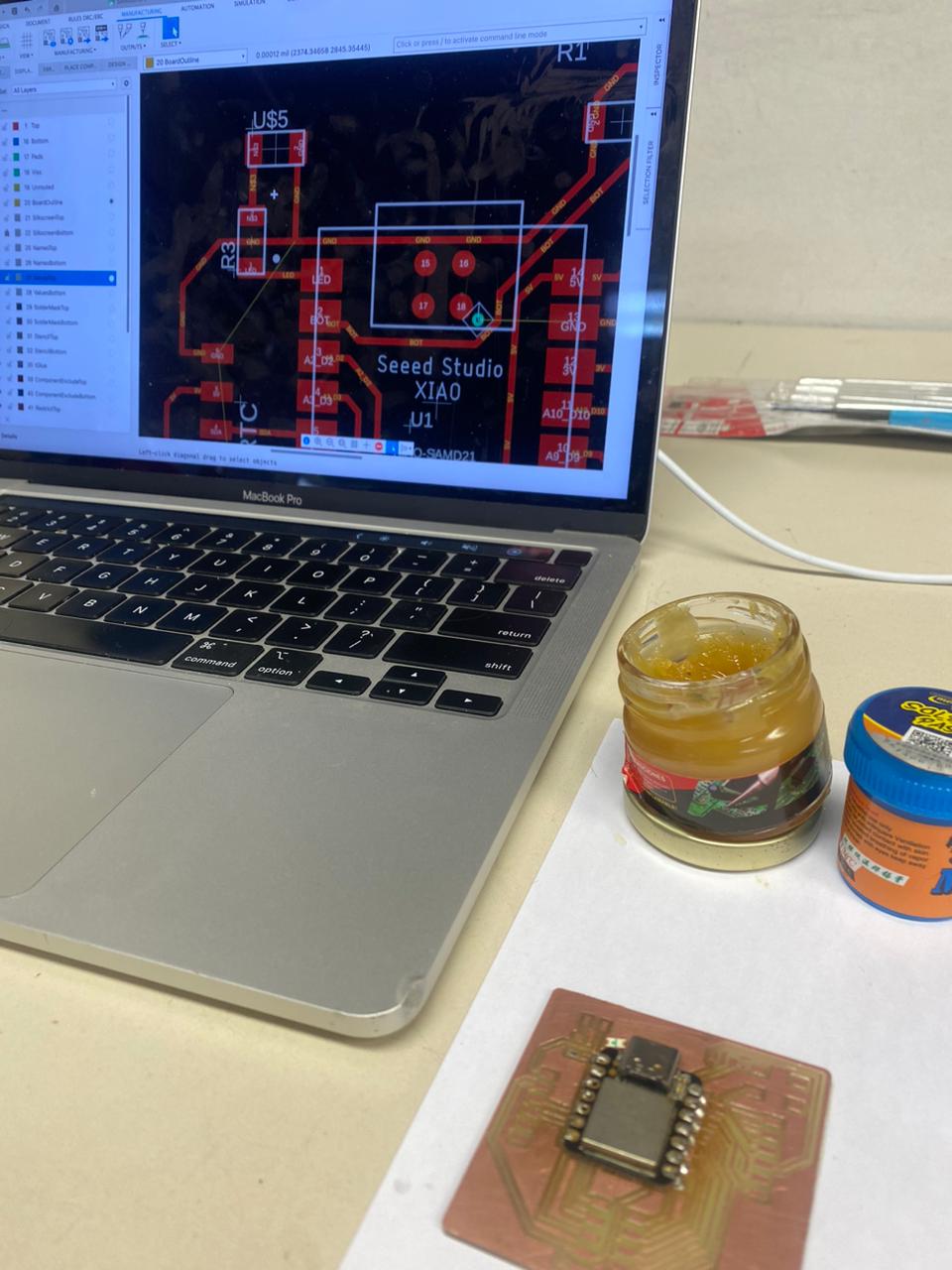
The first thing to do is the design of the board. The software I used was fusion 360, incorporating the electronic board design plug-in. This plug-in is quite similar to the Eagle software, also from the Autodesk company, however they recently announced that this Eagle software will no longer be available so that it can be incorporated into fusion 360.
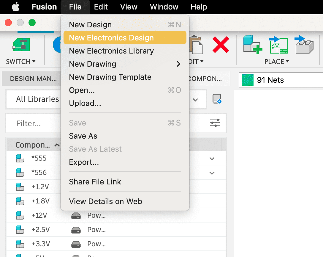
The design has 2 main parts: the schematic and the PCB design. First the schematic is designed, and then the tracks are joined in the PCB design.
Likewise, we must import the libraries that we will use. We must work with the fabacademy library and the seeduino library to have the dimensions of the copper tracks that will be cut. To import library, we must go to library and open the library manager. This is where we import the files we want to contain the libraries we want to use.

The schematic section allows us to add the components we need to design the board. I chose to add a button, an LED diode integrated into the board, two 1x6 header pins and one 2x5. The LED, as well as the button, are each connected to a 1k ohm resistor for optimal operation.
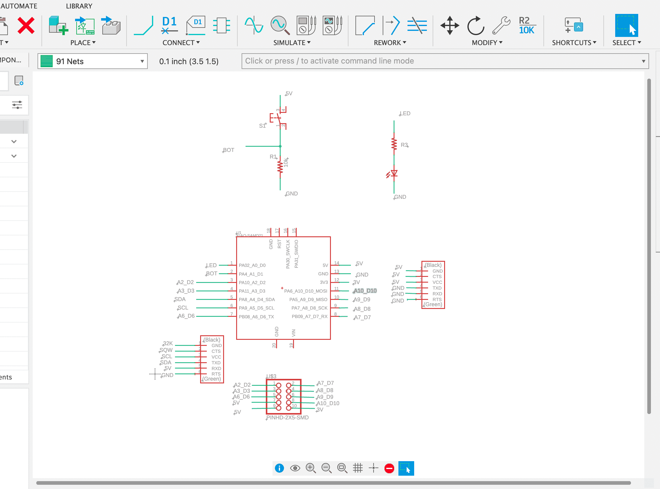
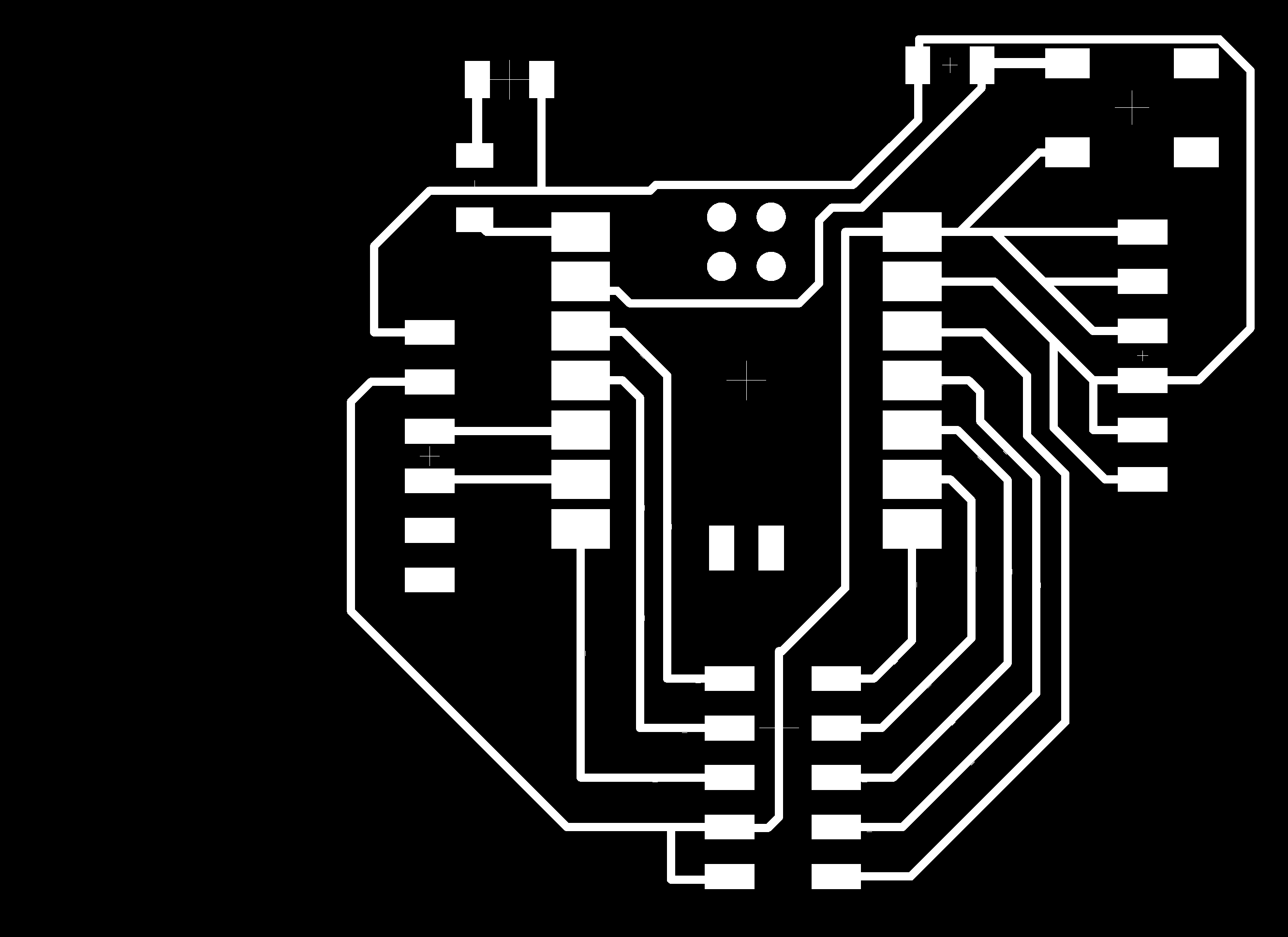
On the other hand, the PCB board section allows us to make connections between the components previously added in the schematic, and we can go from one view to the other to edit the board. In this part, we must test every possibility of the connections so that the board is as efficient as possible.
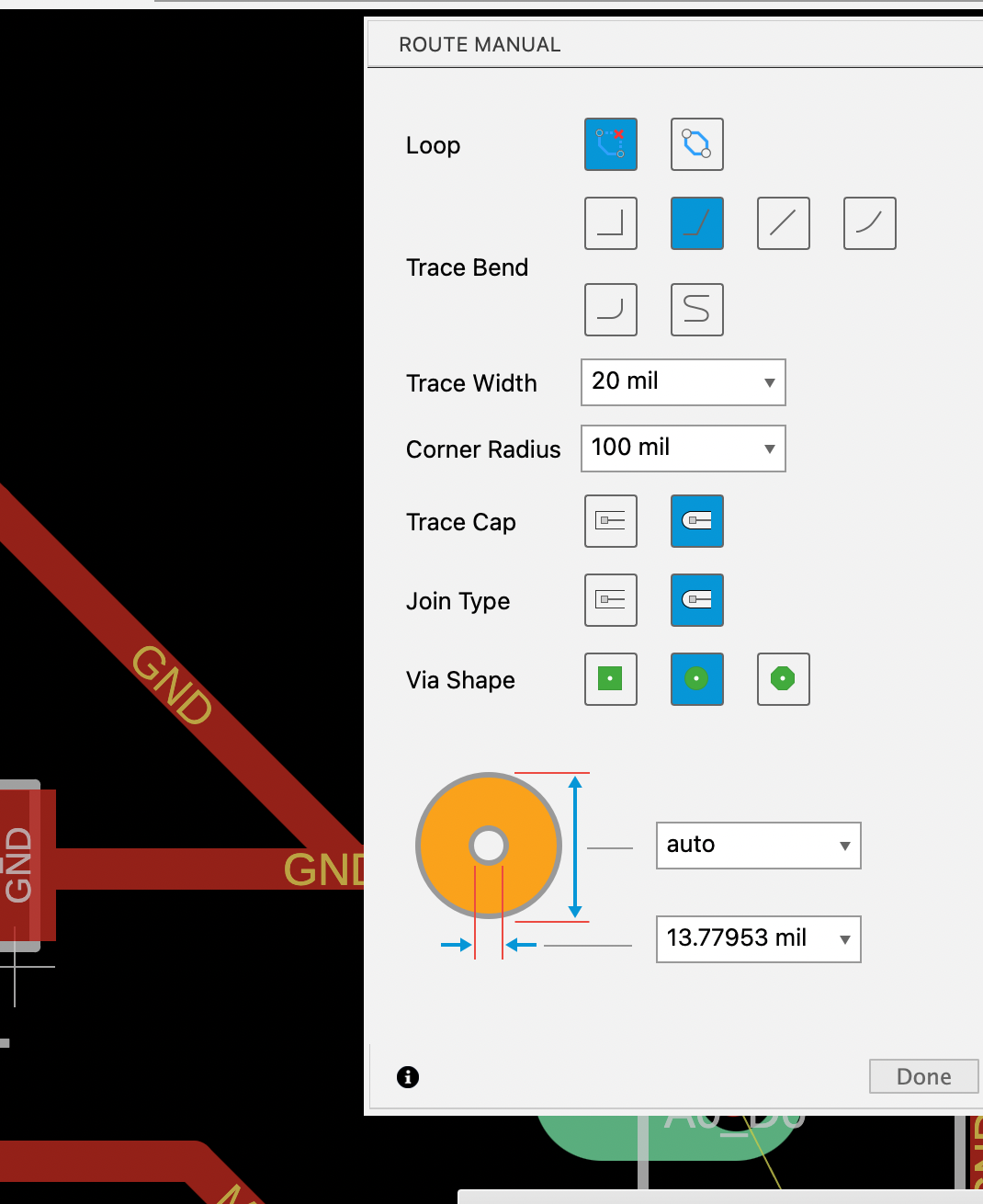
The red line corresponds to one layer and the yellow line to another. It is necessary to differentiate these layers because when it comes to manufacturing, for the red layer which is the tracks we will use a 30 degree milling cutter, while for the yellow layer which is the contour we will use a 0.8mm flat mill.

The "line width" refers to the thickness of the copper traces that are printed on the circuit board. These traces connect the various electronic components on the PCB.
Line Width:
Definition: The thickness of the copper traces on the PCB.
Unit: Typically measured in mils (thousandths of an inch) or millimeters.
The 20 mils I used means that the copper traces are 20 thousandths of an inch thick.
After the design in fusion 360, I used the Flatcam software to generate the G-code file. For this project, two files were generated: one for the tracks and one for the outline.
FlatCAM is a computer-aided manufacturing (CAM) software used primarily for creating toolpaths (G-code) for milling Printed Circuit Boards (PCBs) and other types of flat materials. It's an open-source program designed to take PCB designs (typically in Gerber format) and generate the necessary instructions for CNC (Computer Numerical Control) machines to produce the PCB.
Flatcam works with Gerber format files generated by the fusion 360 software. These files are exported in a compressed folder, from which we choose the route and contour files to load them into flatcam.

After the G code files are generated, we load one by one into the Roland machine so that in first place the tracks are cut and then the contour, having to change the mills when loading each g code.
It is important not to move the part at any time during manufacturing so as not to lose the position of the X and Z axes.

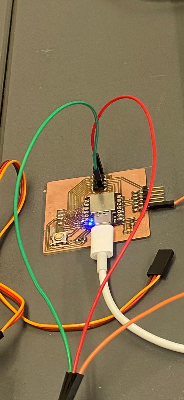
Finally, I proceed to solder the SMD components to the manufactured board, being very careful not to join 2 or more tracks.
Finally, I would like to make a comment about both ways of manufacturing boards learned so far. The first one where MOODS online was used is convenient for generating G codes without having to install any software, which is quite advantageous in case we want to do something quick and efficient. The second way, which is described this week using the Flatcam software, is suitable for doing more detailed work, where we want to specify some or all of the manufacturing variables.
Group assignment
What I learned from this group experience was how to measure voltage in parallel and current in series using a multimeter.
My contribution to the group work was to measure the pwm signals on the oscilloscope that are recorded on the LED. The use of this oscilloscope was of vital importance for the following weeks, where we had to test the output or input signals to our boards. This tool allowed us to know if our programming code was working correctly.
For Inputs week, I also used this oscilloscope to test the input signals to the boards.
Here is the link to the group assignments:
Files: