Week 7 assignment: computer-controlled machining
Summary
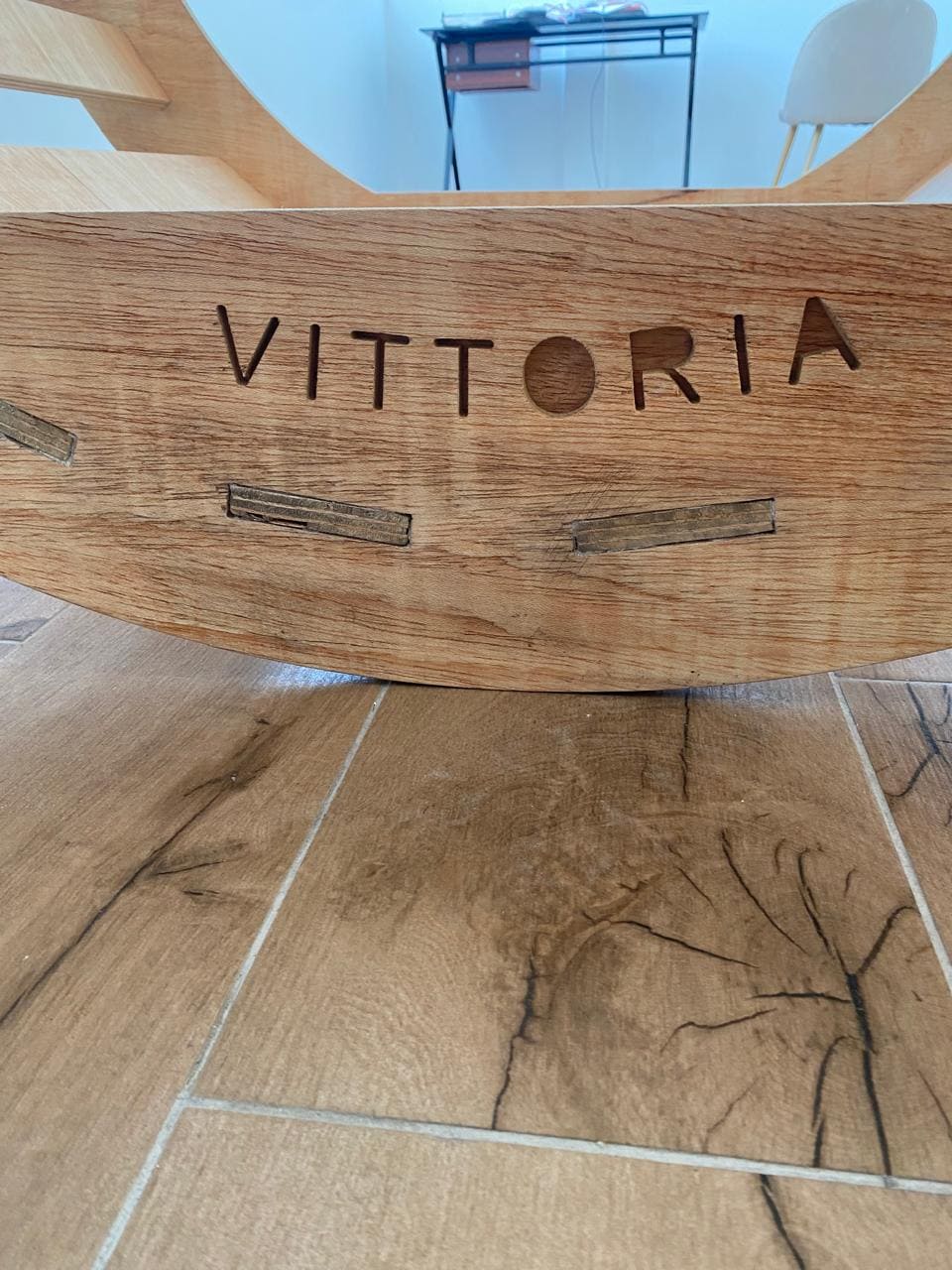
This week's goal is to make (design+mill+assemble) something big (~meter-scale). I did a wooden rocking chair for my daughter, starting from the design, generation of the g code and finally the assembly.
Process
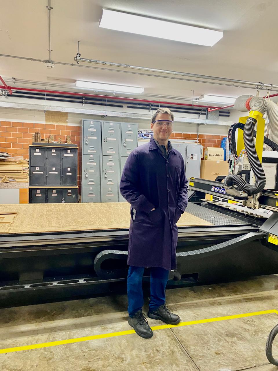
Safty first
It is mandatory the following:
-Use of safety glasses o protect eyes from flying debris.
-Hearing protection to safeguard against high noise levels.
-Appropriate clothing, such as long sleeves and pants, to protect from cuts and abrasions.
-No loose clothing or long hair that can get caught in the machinery.
-Gloves for handling the stock.
-Steel toe shoes.
Key Components and Functions of the Multicam 3000
Machine Frame and Gantry
Frame: The robust structure that supports the entire machine, providing stability and reducing vibrations during operation.
Gantry: The moving bridge that spans across the work area, supporting the spindle.
Spindle
The high-speed motor that holds and rotates the cutting tool (router bit). It is the main component responsible for cutting, drilling, and milling the material.
Tool Holder and Collets
Tool Holder: The device that secures the cutting tool in the spindle.
Collets: The components that grip the cutting tool within the tool holder, ensuring it is firmly secured.
Cutting Tools
Various types of router bits designed for different materials and cutting purposes, like end mills.
Worktable (Bed)
The flat surface on which the material is placed and secured for machining. It includes a vacuum system and we use a sacrifice table.
Control System
Control Panel: The interface used to operate the machine, input commands, and monitor the machining process.
Computer Numerical Control (CNC): The computerized system that interprets the CAD/CAM software instructions and controls the movement of the machine. Here you upload your G-code.
Linear Guides and Bearings
Components that facilitate smooth and precise movement of the gantry and spindle along the X, Y, and Z axes.
Drive Motors and Transmission Systems
Drive Motors: Motors that power the movement of the gantry, spindle, and other moving parts.
Transmission Systems: Mechanisms that convert the rotational motion of the motors into linear motion.
Safety Features
Emergency Stop Buttons: Located at various points on the machine to quickly shut down operation in case of an emergency.
Limit Switches: Sensors that prevent the machine from moving beyond its designated travel limits, protecting it from damage.
Dust Collection System
A system designed to remove dust and debris generated during machining, keeping the work area clean and maintaining air quality. It has a strong sound.
Design
The manufacturing of this chair began with the design made in the fusion 360 software. To design the sockets where the tables that will support the weight go, I had to use the circular pattern option so this will ensure that the tables will be distributed in the same distance between each others.

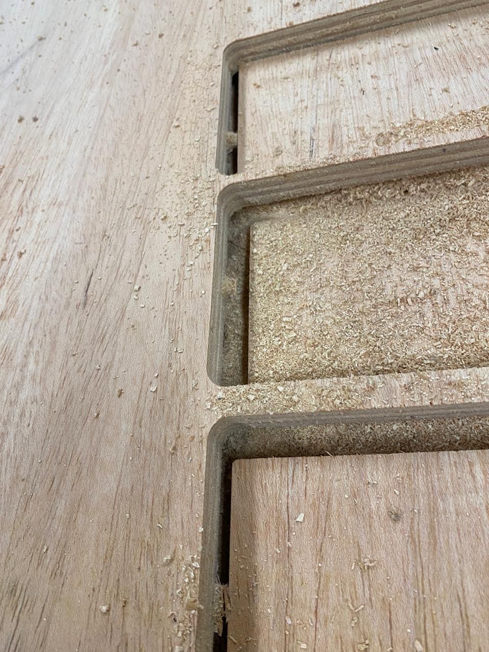
Also, one of the most important considerations was to use the dogbone operation. I had to download directly from the Autodesk website. This operation allows me to make the design considering the diameter of the cutter to be used, and thus the assembly of the piece can be exact.

Generating G code
G-code is a language used in computer-aided manufacturing (CAM) and computer numerical control (CNC) machining. It's a set of instructions that tells a machine tool what actions to perform, such as where to move, at what speed, and what path to follow. G-code commands are typically alphanumeric codes, and they can vary depending on the specific machine and its capabilities. G-code is essential for controlling automated machining processes in industries like manufacturing, woodworking, metalworking, and 3D printing.
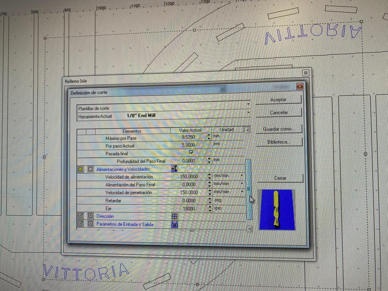
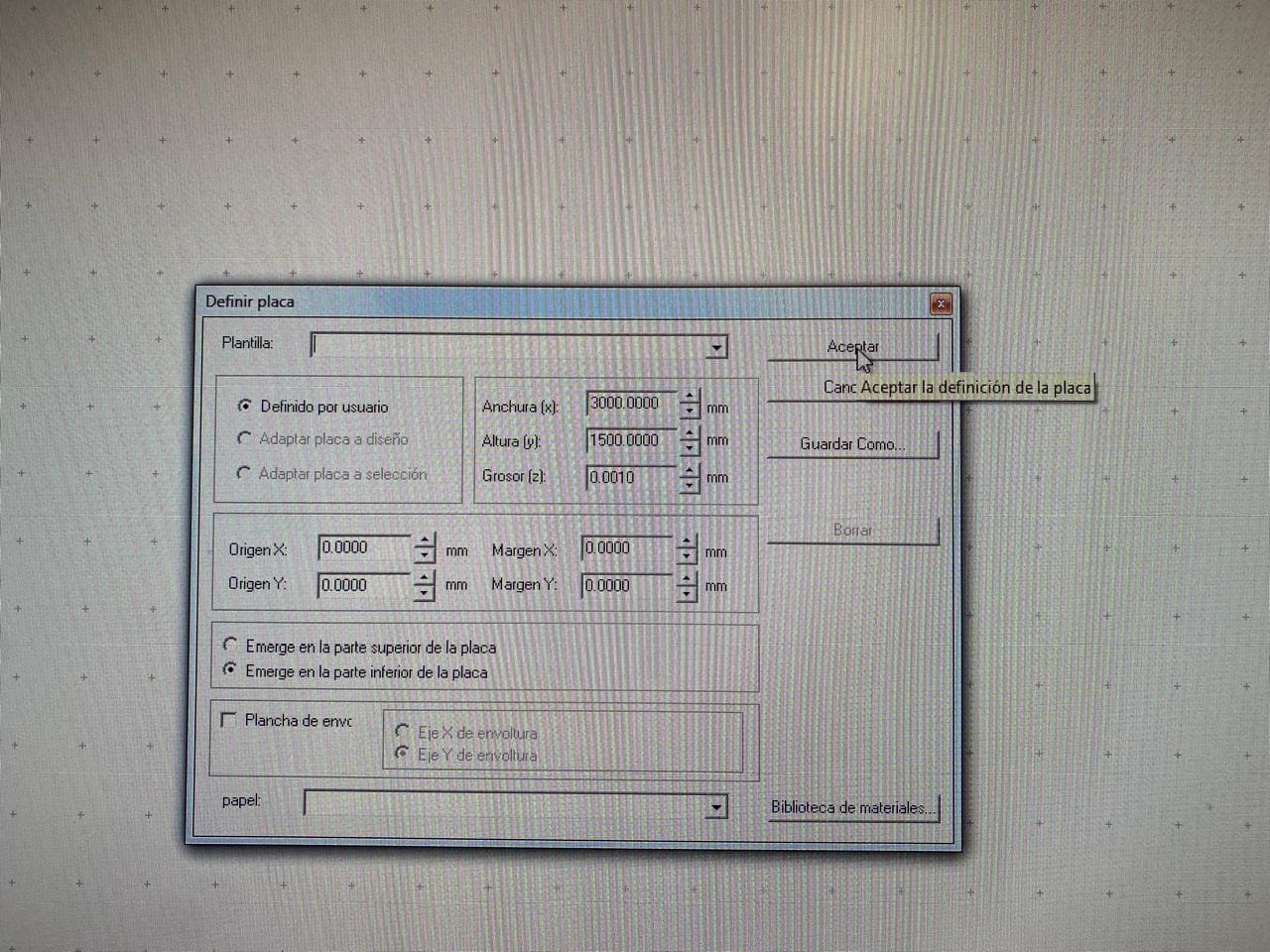
The software used to generate the g code of the design was Enroute. This software has the necessary libraries to process the design and define the parameters for cutting the wood. The raw material used is a full sheet of 15mm thick plywood.
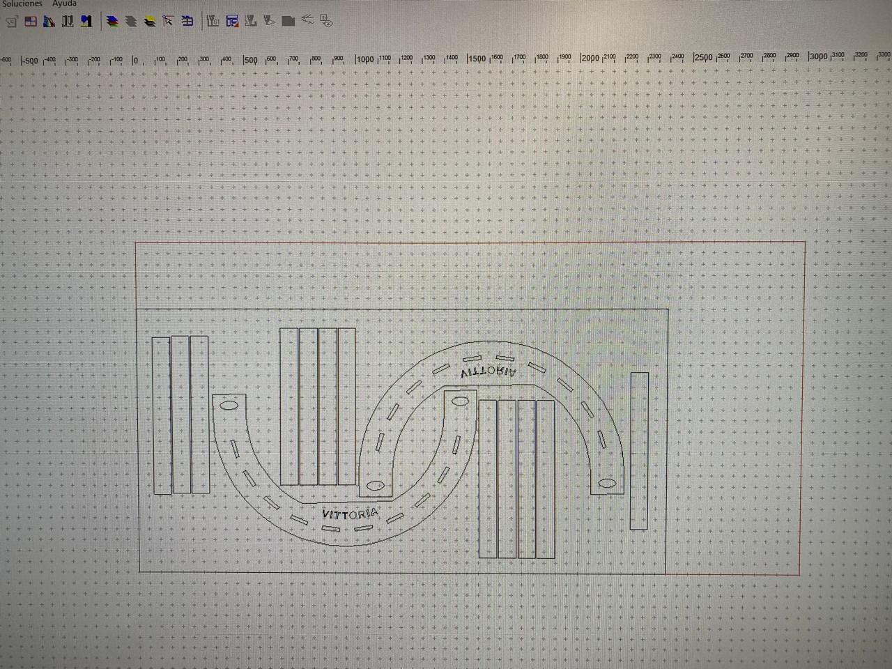
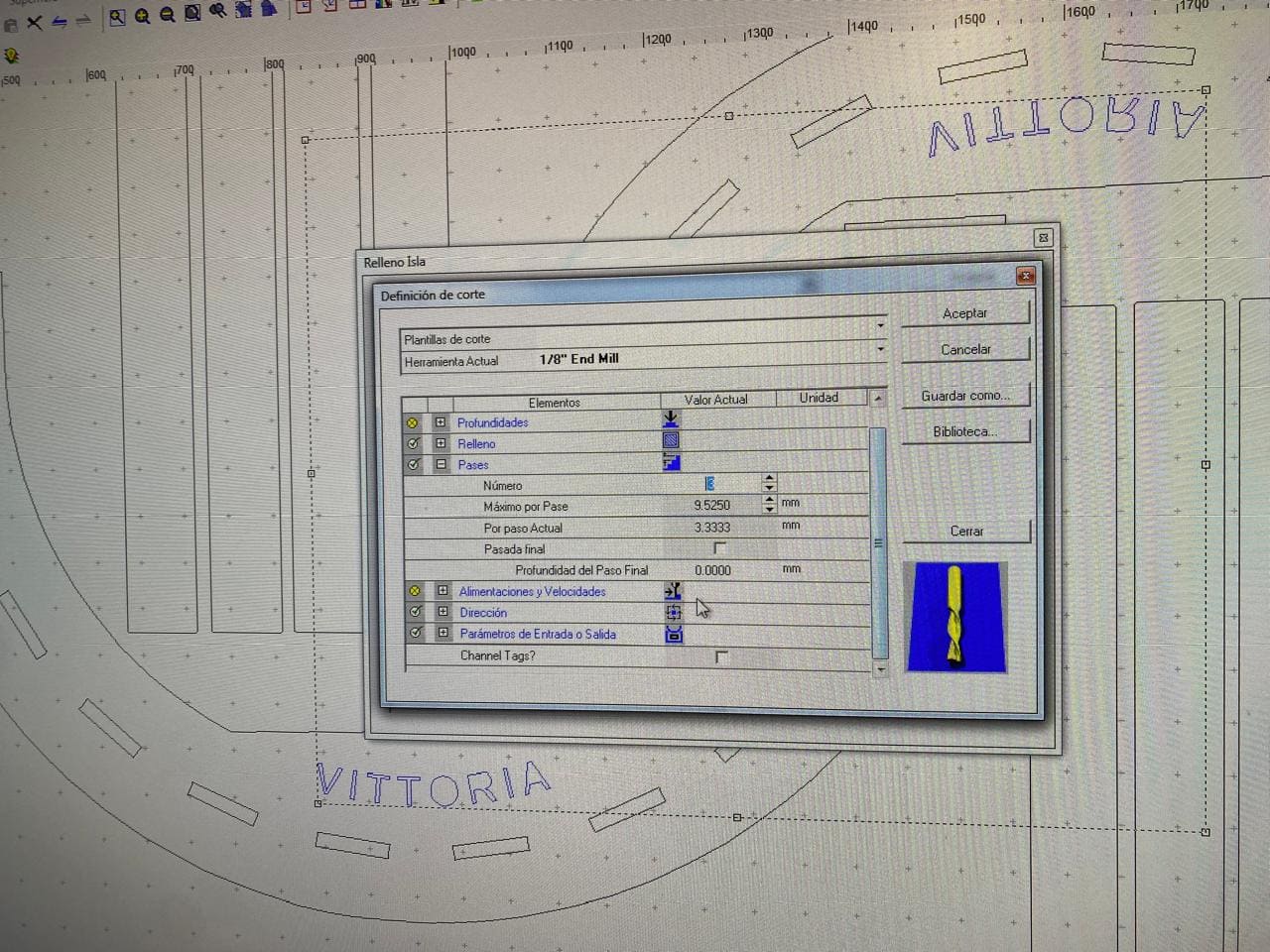
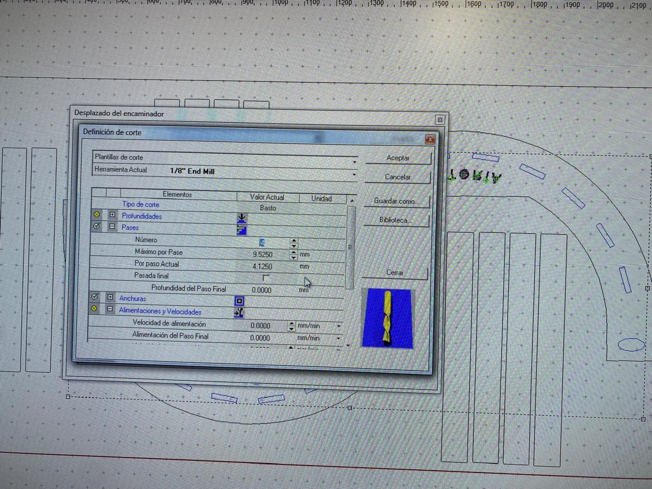
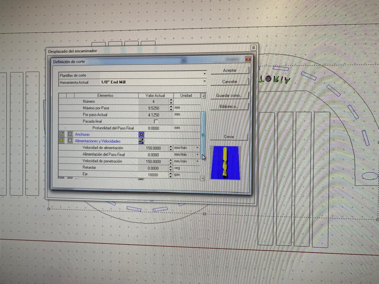
I used an 1/8" end mill for the configuration of the parameters.
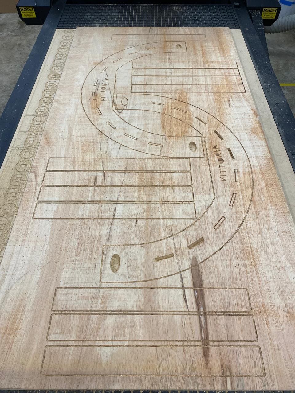
The following image shows how the multicam router machine will perform the cut. As well, it shows how the dogbone operation works, allowing a perfect assembly to be done after the cutting process is complete.

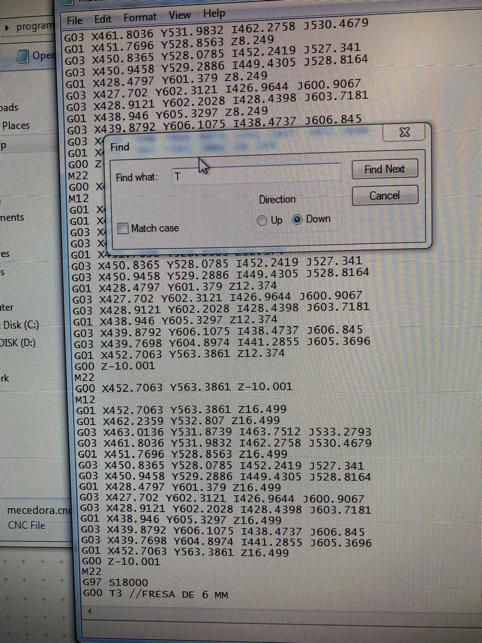
When the g code generation is finished, a small modification must be done. It is to remove the "T" command (which corresponds to the tool change) because in this cutting project we will not be changing it.
Cutting in a multicam 3000 router
This part of the project corresponds to the cut in the router that we have in the fablab. These are some of the features of this machine:
The Multicam 3000 Router is a CNC milling machine manufactured by Multicam, a company specializing in CNC machining and cutting equipment. Some typical features of the Multicam 3000 may include:
Variable working area: The Multicam 3000 is available in different table sizes and working areas to suit the specific needs of users, from smaller applications to large-scale industrial applications.
CNC control system: It utilizes a CNC controller that interprets G-code commands to control the machine movements and milling process. Depending on the model and configuration, it may use different controllers, such as those from the Multicam EZ series or the advanced APEX series controller.
Robust structure: It is built with sturdy and durable materials to ensure stability and precision during milling. This may include components such as a welded steel frame and high-quality linear motion systems.
Milling spindle: The Multicam 3000 can be equipped with different types of milling spindles, which may vary in power and speed. These spindles are responsible for cutting and milling a wide variety of materials, such as wood, plastic, aluminum, and other non-ferrous metals.
Material clamping and chip extraction system: It may include a material clamping system to secure materials during the milling process, as well as a chip extraction system to keep the work area clean and prevent the accumulation of debris.
Intuitive user interface: The Multicam 3000 may feature an easy-to-use user interface that allows operators to program and control the machine efficiently, as well as make adjustments and diagnostics in case of issues.
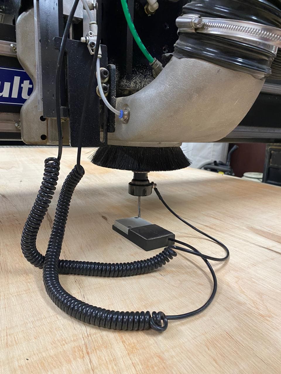
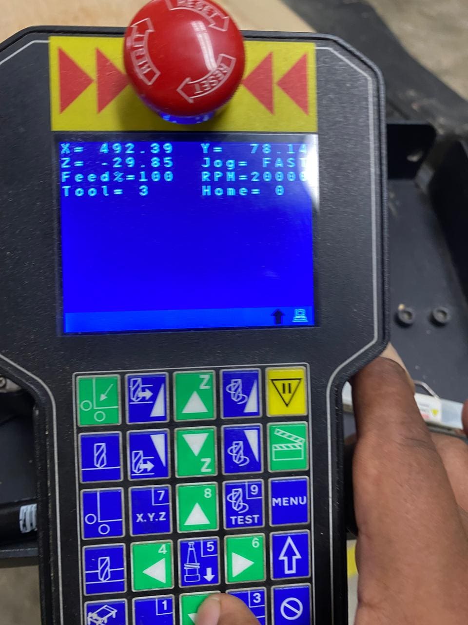
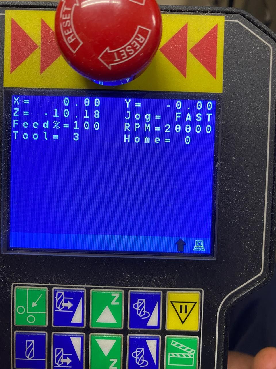
As with the other machines used previously, the first thing we must do is establish the "zero" on the z axis. This is done by calibrating the cutter to be used with a special device on the router. We must also set up the X and Y axis, as seen in the following image:
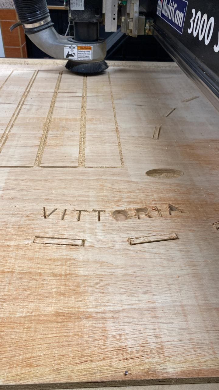
After calibrations, the cutting process begins.
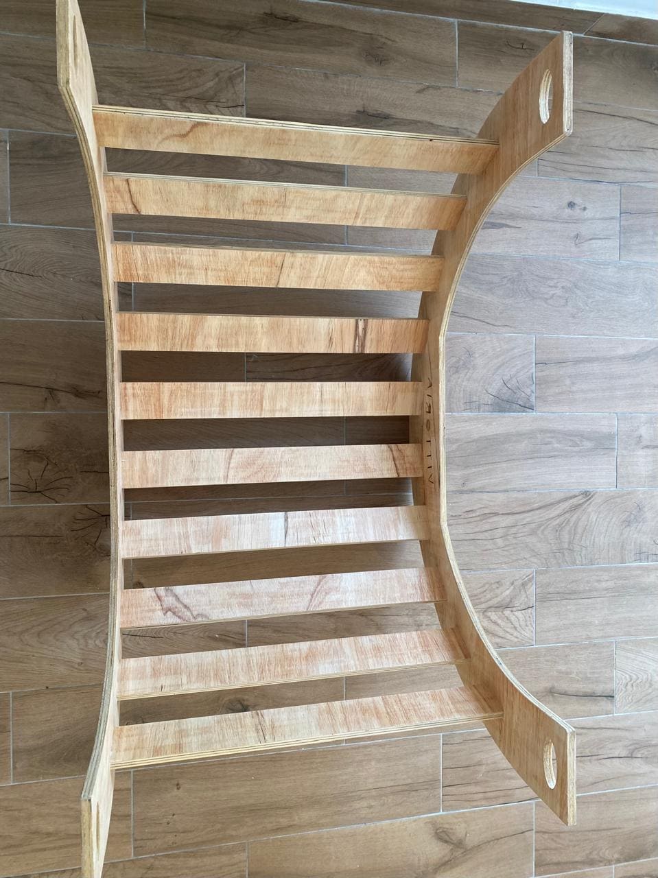
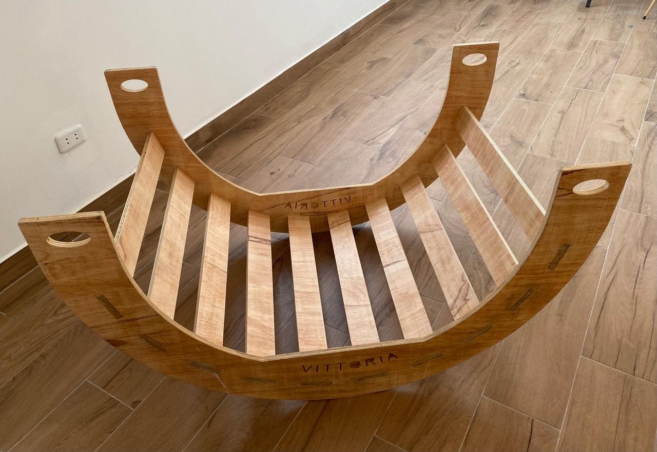
Finally, all the pieces are assembled:

Group assignment
What I learned from this group experience was the the safety protocols and procedures, as well as the emergency procedures, like the buttons. I also learned the speeds and feeds of the round mill we used.
I understood how lace cut out of wood is made, having different types that are shown on the group page.
My contribution to this week's group work was working with the dog-bone corner, alongside varying tolerances of 0mm (needs sanding), 0.1mm (press-fit), and 0.2mm (smooth fit).
Here is the link to the group assignments:
Files: